Finding the optimal locations for the upper lateral links wasn't the last hurdle I'd have to jump, but it certainly proved to be one of the most challenging. There were a lot of variables to consider. My wish list included wanting:
1. a static rear roll centre height of approximately 7 inches;
2. minimal roll centre movement under a wide range of chassis roll;
3. a 0.7:1 camber to chassis roll angle ratio; and
4. positive, or no toe gain.
The challenge was on to determine if there even existed a set of points (one for the inboard and one for the outboard pivots) that would result in the performance I was seeking, without them interfering with anything. For example, a set of pivot points that resulted in great theoretical performance but that were buried in the engine weren't going to work. I also wanted to:
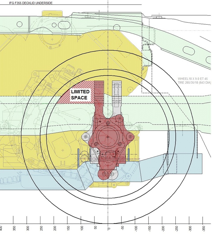
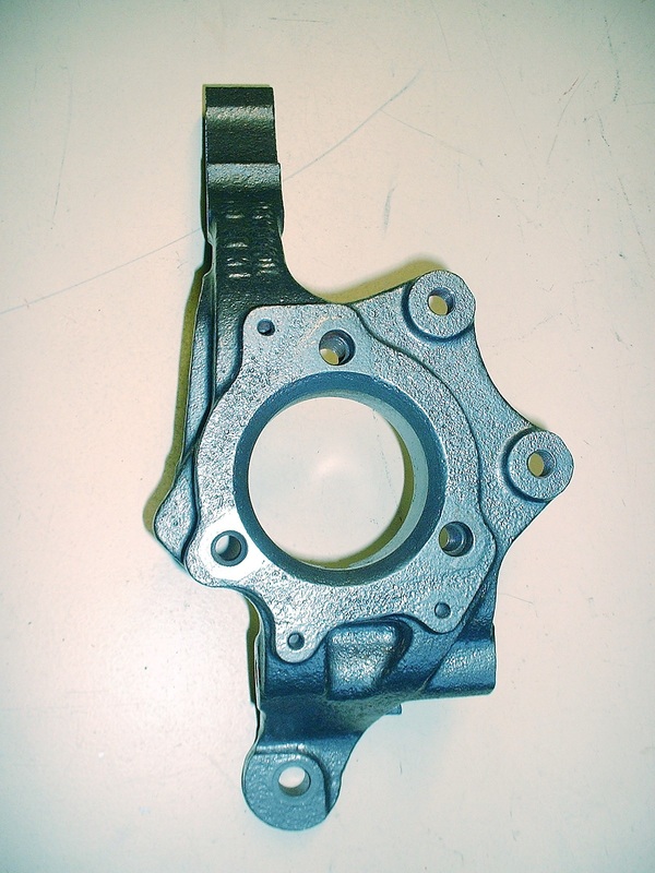
a. use one of the two strut mounting holes on the top of the knuckle if possible to locate the outer pivot points of the new upper links;
b. find an inboard location suitably close a structural member to solidly anchor the inboard mounts; and
c. leave enough space between the fore and aft upper links for a shock absorber pushrod to fit between them.
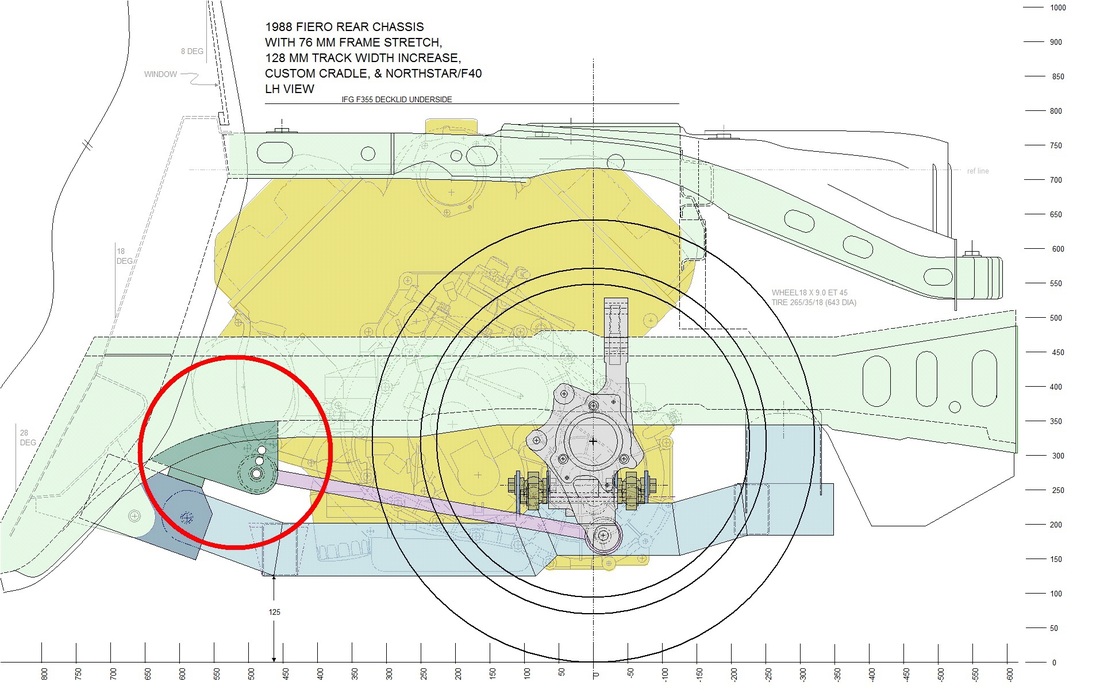
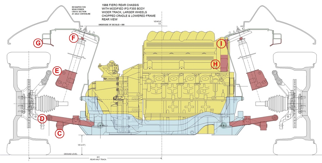
It was a tall order, but as the saying goes, to eat an elephant one must take it one bite at a time. For starters, I knew that both upper inboard pivot points would have to align with each other as viewed from the rear to prevent binding of the entire system. The same was also true for the upper outboard pivots. By starting then with the rear view of the chassis, I would only need to draw one link since the inboard and outboard points would appear in the same location for both links in this view.
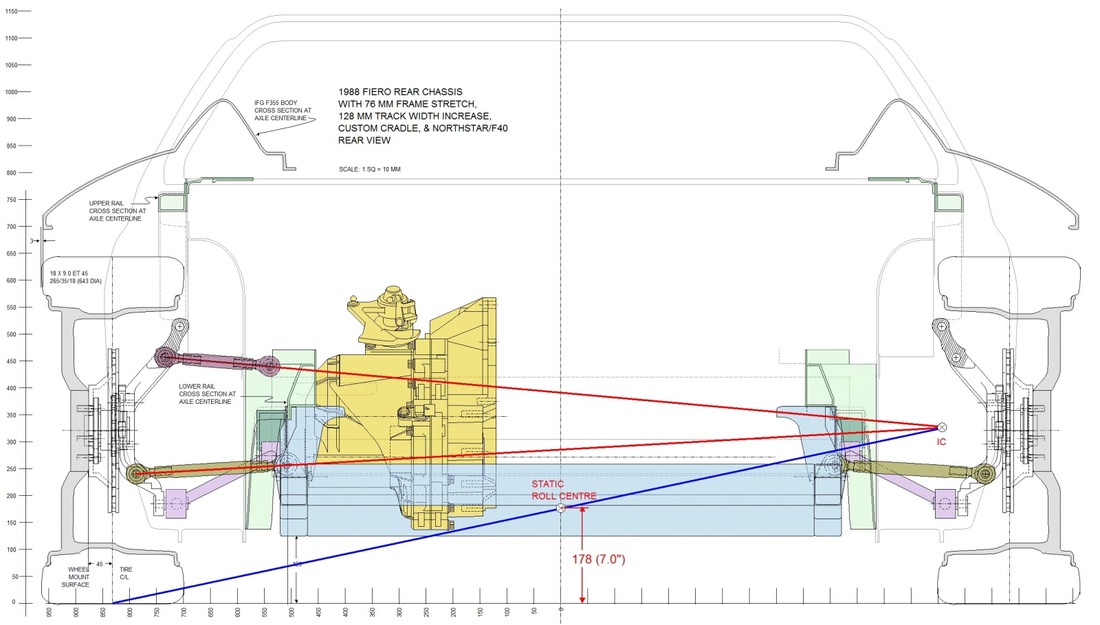
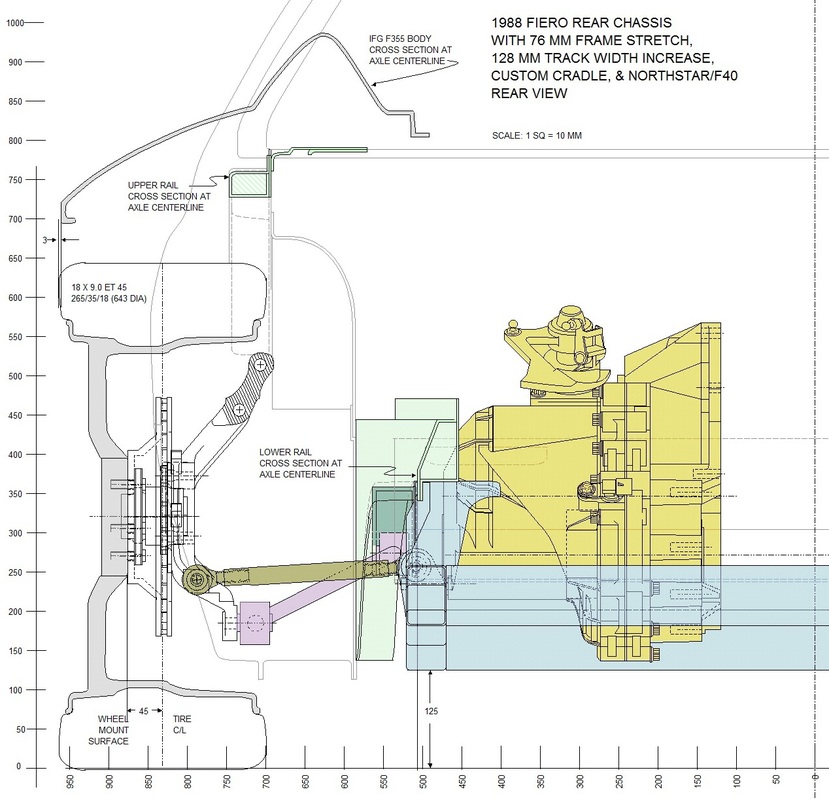
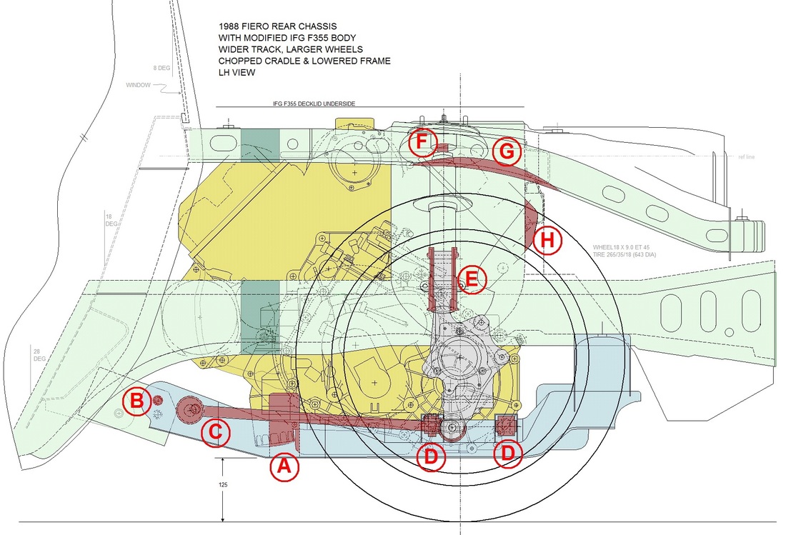
I pulled up my rear view drawings and got to work. I initially chose the lower of the two old strut mounting holes on the knuckle for the outboard pivot point, and chose a specific downward angle such that it would create my desired static roll centre height of 7 inches, like this:
I then tilted the chassis digitally through several degrees at a time (as I has done with the stock Fiero analysis in earlier posts) and watched what would happen to the roll center and the camber of both tires after redrawing all the links at their new angles. I then repeated this exercise a dozen times, changing the location of the inboard and outboard pivot points until I got a feel for how the camber and roll center movements were impacted by various displacements of each pivot point. I was amazed at how sensitive the camber change was to very minor inboard pivot point changes.
I discovered that using the upper hole in the top of the knuckle allowed far better geometry than the lower hole. Then, after much trial and error, I found what appeared to be an optimal position for the inboard end of the upper lateral links as well. Here's the last iteration:
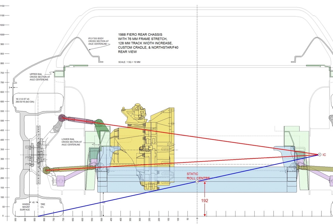
With a minor concession to the static roll centre height being 7.5" above the ground, manual calculations pegged the roll centre movement within a very small "window" and the configuration came very close to the 0.7:1 camber to chassis roll angle I was looking for. I still needed to verify this with the Lotus Suspension Analyzer program, but my manual results were very encouraging. So for now, I had the Y and Z but still needed the X coordinates to feed the program. For that I needed to work with the top view.
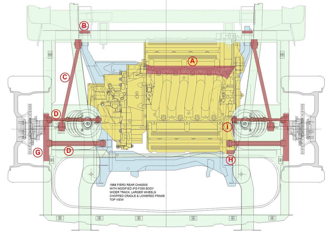
To keep things as simple as possible, I decided to run the aft upper link from the knuckle straight across to the chassis, making it a true lateral link that is perpendicular to the centreline of the car. That then completed the information necessary for the aft link. Four links down... one to go.
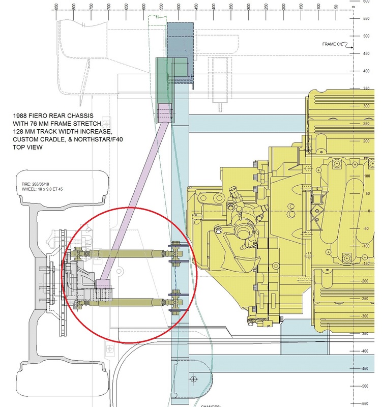
Locating the forward upper link and determining its length was next. It was a lot easier to do than to explain, but here goes: I knew I couldn't make the forward link another true lateral link because the knuckle top needed to be triangulated to keep it from flopping around. To triangulate it, I wanted to choose an inboard location for the pivot point as far forward as possible. That would give the knuckle the best possible rigidity and make the most amount of room for the shock absorber system. I had also determined that its pivot point had to lay on the same axis as the rear link's inboard pivot point to avoid binding. So I extended a line from the centre of the rear link's pivot point forward. The forward link's pivot point would have to lay on this line, so I simply chose a location along the line that would afford enough room on the top of the frame rail to fabricate the mounts for the link without having them protrude into the engine bay. Simple right?
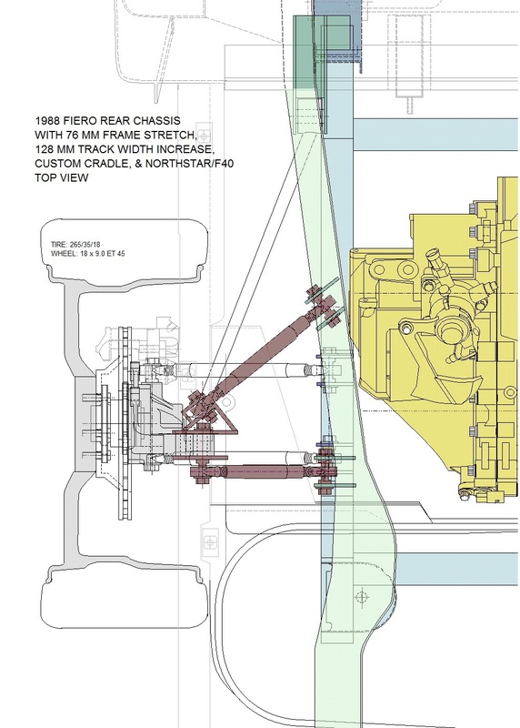
The knuckle-end was then easy to find after accounting for the bulk of some bracketry that would be needed to accommodate the angle of the link at the knuckle. Here's the top view showing the configuration of both upper links. Technically, the rear link is a true lateral link, while the forward one is an upper trailing link:
Before spending any more time designing actual mounting hardware for the links, the next step was getting the 3D coordinates of the pivot points off to my fellow Canadian, Zac, to see how this system would behave using the Lotus simulation software.

 RSS Feed
