Having found the 3D locations of the major pivot points for the new front configuration, I was able to churn out the performance data from the Lotus Suspension Analyzer program. I expected an impact on anti-dive since it's related to the height of the centre of gravity, and I expected a drop in the roll centre height due to the drop spindles. I didn't expect much else of an impact except perhaps for the longer control arms to have a damping effect on most parameters. I was wrong.
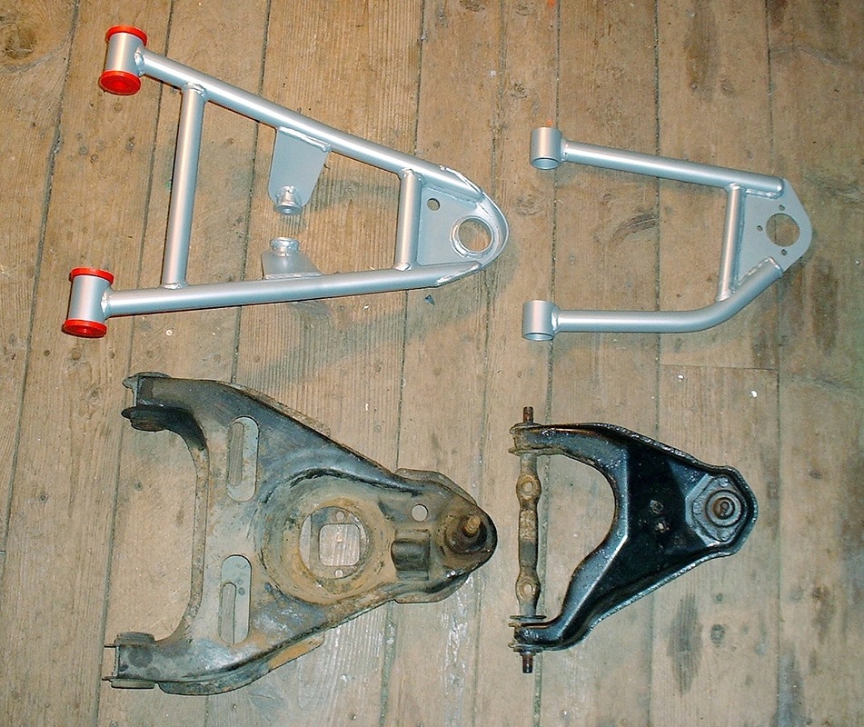
Most of the kinematics had taken a turn for the worse and it took a bit of puzzling to figure out why. What I had overlooked was that by lengthening both control arms equally by 76 mm, I had inadvertently changed the ratio between their lengths. The stock lower control arm being 350 mm and the upper at 216 mm resulted in a 1.62:1 ratio. Lengthening them equally however resulted in a 1.46:1 ratio that negatively affected camber, toe, anti-dive, and roll moments. The biggest hit was to the lateral roll centre movement which went from about 18 mm on either side of the centre line in stock configuration (blue line), to 238 mm in the new layout (orange line).
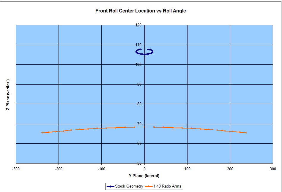
Each dot represents a half degree of body roll up to a maximum of 6 degrees. While the change may not be terribly significant in real world performance, I couldn't take the chance that my provincial inspector would disagree.
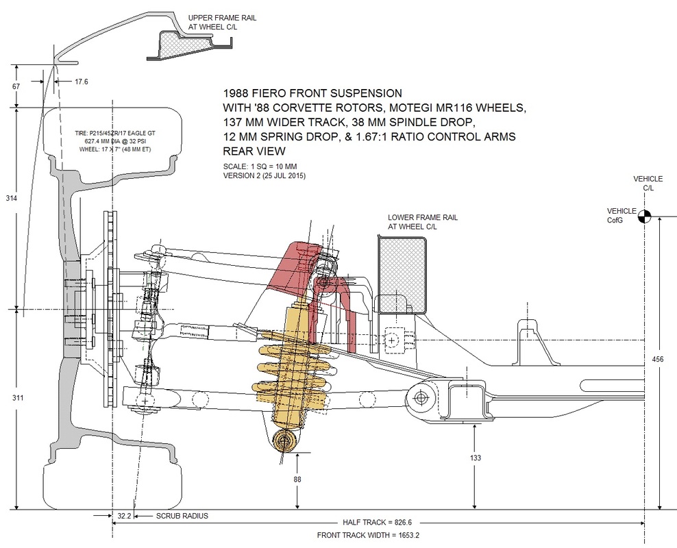
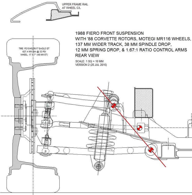
On paper, the solution was simply not to lengthen the upper control arm as much as the lower one and return the ratio close to stock. After a few simulations on the Lotus Analyzer, a sweet spot was found when the upper control arm was lengthened by only 41 mm:

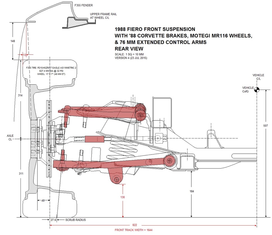
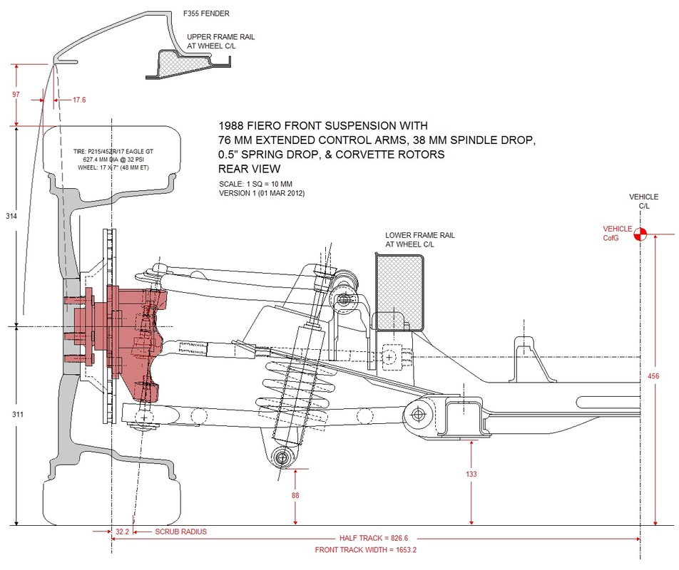
Shortening the upper control arm caused a few more headaches to be resolved though. From the drawing above the pivot shaft axis for the upper control arm no longer lined up with the mount (in blue) on the cross member. In fact, the pivot shaft now interfered with the upper shock tower (in green). Relocating both the control arm mount and the shock tower outboard would satisfy both issues, and as it turned out, there was only just enough room:
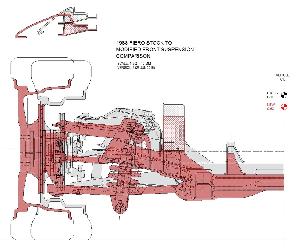
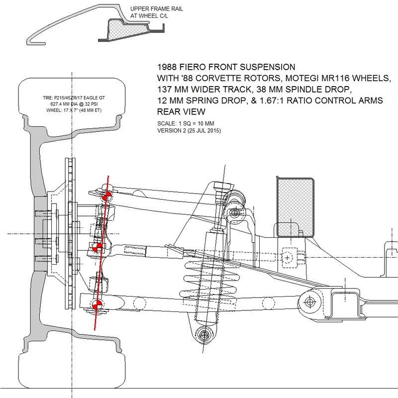
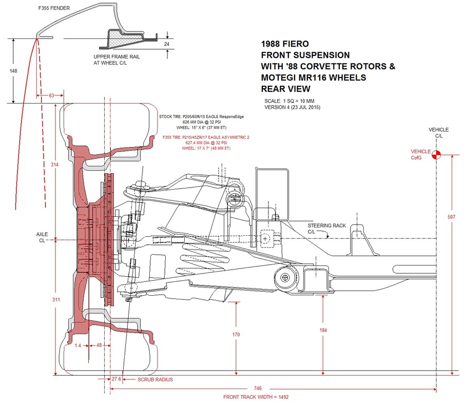
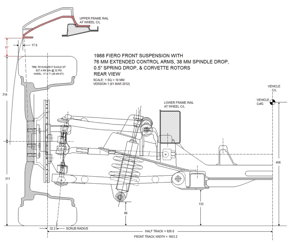
With all the measurements removed and the drawing cleaned up a bit, this is what the new layout looks like superimposed onto the stock suspension.
So, how does this setup compare with the stock suspension performance? Pretty well, if I do say so myself. Here's the proof of the pudding.
CAMBER VS BUMP
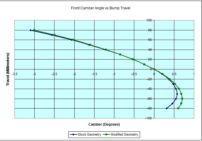
For all intents and purposes the camber gain for both systems is identical in jounce. In rebound, the new suspension deviates 0.3 degrees for the worse at the full 76 mm extension. At 40 mm extension (a far more likely level of rebound) the camber is off by less than 0.07 degrees. The only impact this has on performance is a very slight loss of traction since the tires won't be as flat against the pavement as stock in these extreme conditions.
CAMBER VS ROLL
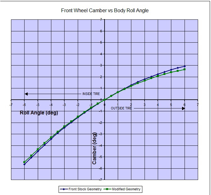
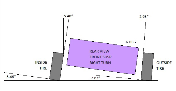
In roll, the new suspension's camber gain marginally out performs the stock set up. To find the camber of the outside tire in a roll, simply pick any positive value for body roll angle along the vertical scale, scroll to the right until you intersect the curve, then read off the camber from the horizontal scale. To find the camber on the inside tire, simply follow the same procedure using the negative value of body roll angle. In every case the tire remains as flat or flatter on the new suspension compared to stock. Here's a diagram showing what the numbers represent at 6 degrees body roll with the new suspension:
TOE VS BUMP
The '88 Fiero front end is statically aligned with 0.30 degrees of toe-in per side, but I've chosen not to show this on the graph below. In the case of the '88 Fiero, static toe is dialled in to account for manufacturing tolerances which when compounded, require pre-compensation to achieve parallel rolling of all four wheels.
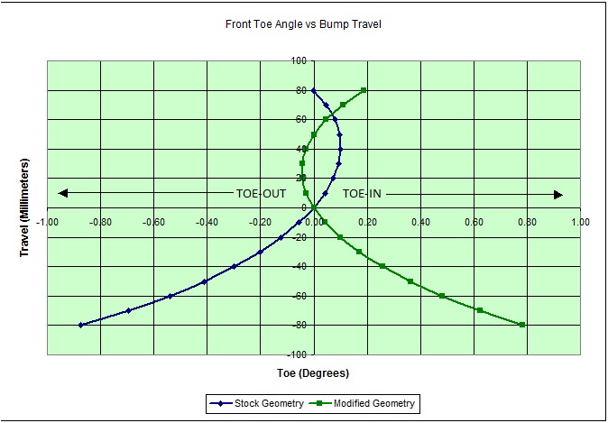
Dynamically though, as the suspension compresses or extends, the toe angle changes in accordance with the curve in the graph. With the stock geometry in jounce (blue line), the wheels initially toe in slightly to about 0.10 degrees until the suspension hits 40 mm of jounce. At that point they start straightening out again until 80 mm's of jounce by which time they've returned to the straight-ahead position. In rebound they start off straight ahead but continually point further outwards (or toe-out) through the entire range.
The reason dynamic toe changes are designed into a suspension system is to change the oversteer or understeer characteristics of the car. For example, when cornering around a left turn, the car's body naturally rolls to the right, causing the right front suspension to compress up in jounce, forcing the right wheel to steer even more in the direction of the turn on the Fiero. This causes the front of the car to oversteer, or turn more than what has been commanded by the steering wheel, at least initially. For a tail-heavy car, this does not help driver confidence. Past 40 mm's of jounce, toe-in stops increasing and starts decreasing, which to the driver inspires more confidence.
Dynamic front toe changes are made possible in one of two ways. The first is by having the outer tie rod end misaligned with an imaginary line drawn between the upper and lower ball joints as viewed from the rear.
Since the outer ball joints and tie rod end didn't change in relation to each other, the change in the performance from the stock to new configuration isn't due to this.
The second way is for the inner tie rod end to be misaligned with an imaginary line drawn between the upper and lower control arm mounts. This is precisely what happened when I moved the upper control arm mount outboard from the stock location.
The result is improved performance over stock by changing front oversteer in jounce to slight understeer (near neutral steer) up to 50 mm jounce (green line in graph).
Well, that's more than enough theory for one post. I'll finish off describing what happened to the remaining parameters next time.

 RSS Feed
