One way to ensure good traction is by having the correct springs and shock absorbers that keep the tires planted firmly on the road despite bumps and dips. Another way is to make sure the tire stays flat in relation to the road surface no matter what the rest of the chassis is doing. Camber control addresses this second issue. Camber is the relative angle between the tire and the road when viewed from the front or back of the car, and like anti-squat, camber changes as the suspension is compressed or extended:
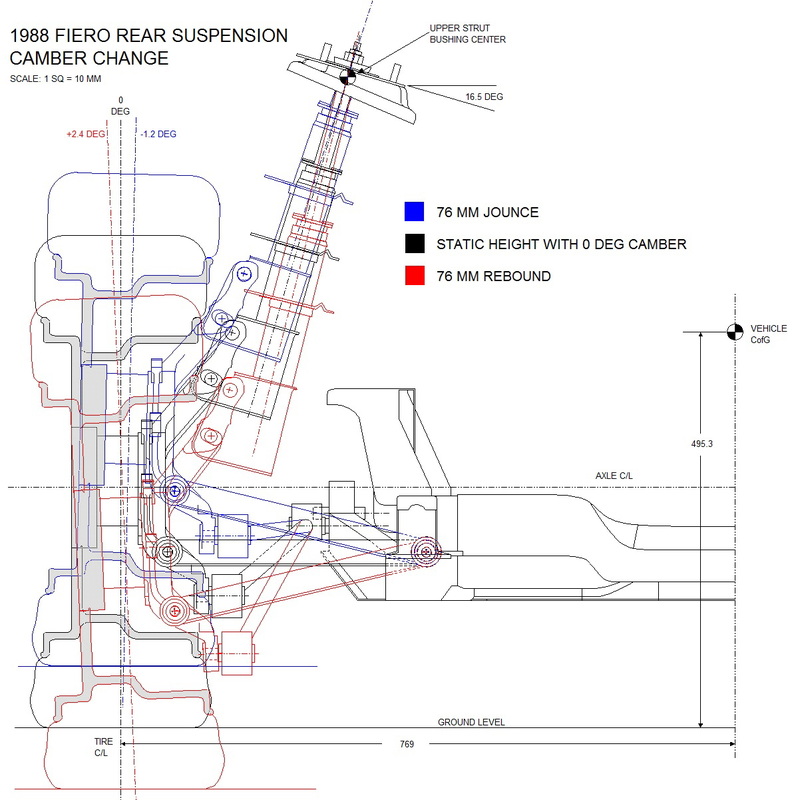
As illustrated above, when the chassis is at ride height the camber of the wheel is zero, meaning the tire patch is flat on the ground (black lines). Compressing (blue lines) or extending (red lines) the suspension causes the wheel to tilt in relation to the ground. Note that an equal amount of compression doesn't result in an equal and opposite amount of wheel tilt on the Fiero.
So how does one figure out just how much the wheel tilts one way or the other, much less decide how much it should? Answering the first question is easy: as with calculating anti-squat, knowing how to manipulate geometry pays off. The wheel actually acts as though it's attached to the chassis by arms that are much longer than the 20" (324 mm) lateral links used on the Fiero. To calculate just how much longer this virtual arm is, follow along referring to the diagram below:
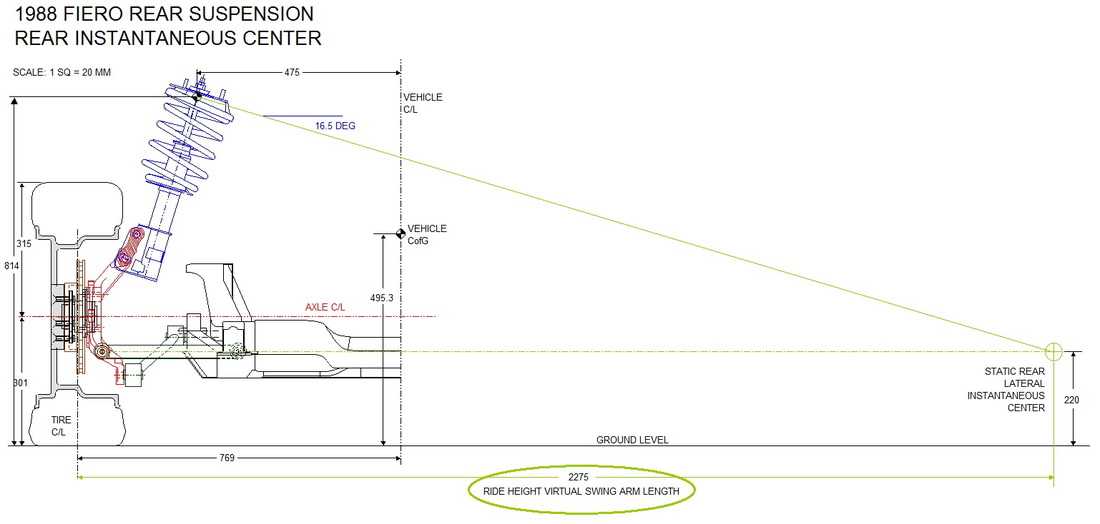
On the ’88 Fiero, which has a Chapman strut rear suspension, the rear wheels move up and down (as viewed from the back) as though they were on levers 7’ 5” (2.275 meters) long despite the much shorter lateral links. The drawing above shows how the virtual swing arm is found by extending the upper green line at right angles to the strut centre line at the upper strut bushing. Next, the green dashed line is drawn through the two pivot points of the lower control arm until it intersects the upper green line at the right of the drawing. The intersection is what’s called the lateral Instantaneous Center (IC) for the rear wheel. The length of the virtual arm that the suspension swings about is the distance from the IC to the centre line of the tire patch as projected on the ground (circled in green). This means that the wheel pivots through an arc as though it were rigidly connected to a 2275 mm long lever.
But this doesn't explain why the wheel tilts a different amount when the suspension is compressed or extended the same amount in opposite directions. To figure out why that happens, the same exercise is conducted as above except this time we'll superimpose all three scenarios at once, namely at ride height, and at full compression and extension:
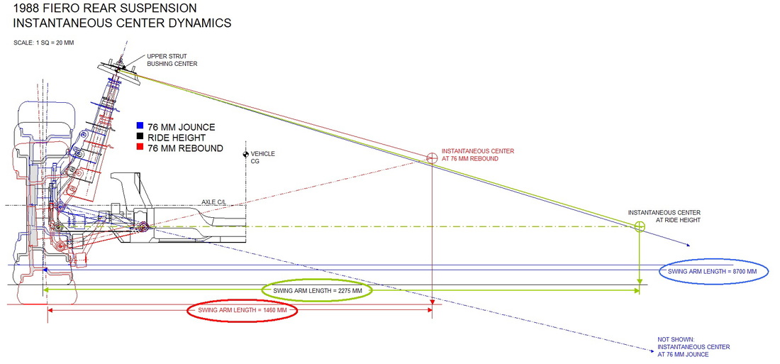
Following the same exercise as above, a red line was drawn through the lower control arm at 76 mm droop until it intersected with the red line drawn perpendicular to the strut. That located the Instant Centre for the extended suspension, from which a line was dropped down to the ground and the swing arm length of 1460 mm was found. Notice how that's a lot shorter than the swing arm length at ride height in green, which we found to be 2275 mm earlier. Next have a look at the same two lines in blue for the suspension in compression. They become nearly parallel to each other to the point that the intersection of the two lines is way off the page. I calculated that the swing arm length is in the neighbourhood of 8700 mm when the suspension is in full compression.
Since the length of the virtual arm that the wheel is hinged to is always changing in length, it should be clear now why the amount of camber is different despite moving the knuckle an equal amount above and below ride height. A shorter virtual arm causes the camber to change more quickly, and a longer arm causes the camber to change more slowly. In fact, the rate that the camber changes can be plotted for every position of the suspension using simulation software. The following graph shows that relationship:
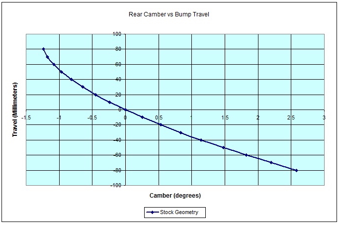
To make sense of the graph, these next three schematics should help, starting with the ride height scenario:
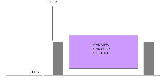
At zero suspension travel as indicated on the vertical scale of the graph, we find that the plotted line intersects the horizontal scale at zero as well. That means that the tires will be flat against the ground like the drawing above.
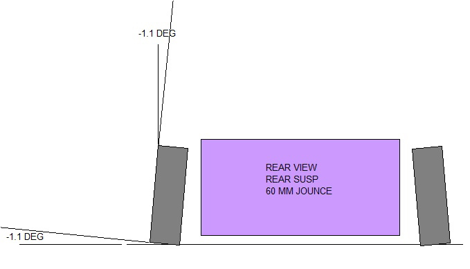
At 60 mm suspension compression, we find that the graph intersects the horizontal scale at -1.1 degrees. That means that the tires are no longer flat with the ground and are tilted inward at the top like this:
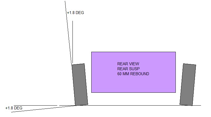
Lastly, at 60 mm extension (or rebound), the tires are tilted outward at the top by 1.8 degrees like this:
So that brings us to the second question: how much should the wheels tilt? As we saw in the previous post covering anti-squat, acceleration causes the rear end to compress, which, because of camber geometry causes the rear wheels to tilt in relation to the road and decrease the available traction! So why would anyone want to build camber change into their suspension? That's the subject of the next post.

 RSS Feed
