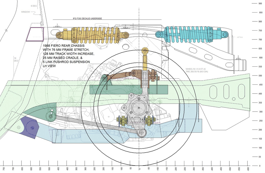
So why a pushrod shock absorber system? Clearly the "WOW" factor was part of it, but it wasn't the deciding criteria. Back in Post #29, I lowered the chassis to get the right wheel-to-fender gap but doing so also used up most of the original strut's travel. That, combined with the knuckles being much further outboard than stock would have resulted in a significant reduction in performance from the strut-type suspension, so I looked at alternatives.
The first thing I ditched was the idea that I'd be able to fit a vertical shock absorber. Orienting the shocks in any other configuration would require a pushrod and bell crank system. I considered running the shocks inward, meeting at the middle of the engine bay, but there simply wasn't enough room with the very wide Northstar engine. There was however enough room longitudinally toward the rear and longitudinally toward the front as the blue and orange shocks show respectively, here:
The structure of the Fiero's chassis favoured the forward direction so that was my starting point. What came next was a concentrated effort to understand the mechanics of pushrod and bell crank assemblies. There was a lot more than met the eye.
To start with, the location where the pushrod is connected to the knuckle influences the total pushrod travel, which doesn't necessarily equate to the same amount of wheel travel. Then, the shape and size of the bell crank influences the rate of the shock's compression, the path, and the total travel of the shock absorber.
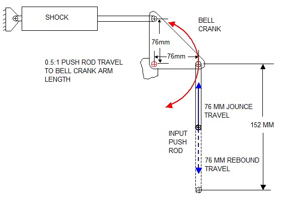
For example, here's a typical pushrod bell crank system where the input pushrod is at ride height. The blue arrows show the pushrod can travel 76 mm in either direction. In this example, the bell crank arm lengths (76 mm) are equal to half the total travel of the input pushrod (152 mm) giving a 0.5:1 ratio between the bell crank arm length and the pushrod travel:
This is the same bell crank as above, except the pushrod has been moved to the extreme limit of its 76 mm upward travel:
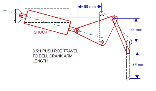
Notice how the 76 mm vertical input at the bottom of the pushrod translates to only 68 mm vertical travel at the top of the pushrod. That's because the top end of the pushrod travels in an arc defined by the size of the bell crank. Notice too that the shock absorber is compressed by only 68 mm as well, which is 10% less than the input pushrod travel.
The other notable issue is that the axis of the shock absorber (green dashed line) drops nearly in-line with the centre pivot of the bell crank. If the bell crank were any smaller, it would rotate to an over-centre condition locking the shock absorber and the entire suspension in the fully compressed state.
To reduce both effects, the bell crank arm lengths must be longer than half the pushrod travel. Here is an example of the same system as above except the bell crank arms are equal in length to the total pushrod travel (152 mm):
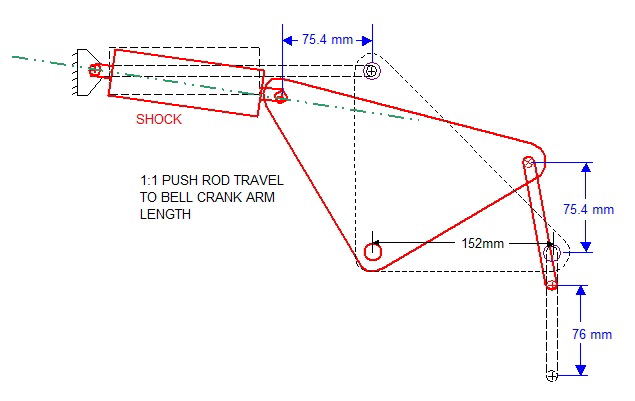
Notice how only 0.6 of a millimeter is lost to rotation in both the pushrod and the shock absorber. With this configuration there is no danger of an over-centre lock developing either since the axis of the shock never comes close to lining up with the bell crank pivot point. Of course in my case, physical constraints prevented the use of bell cranks with such large dimensions so a compromise had to be made.
After playing with different designs, I eventually chose the crank arm lengths at 107 mm to ensure everything would clear the underside deck lid. That gave a 0.7:1 ratio between the bell crank arm length and the pushrod travel. At 76 mm of push rod travel, this design would produce a very efficient 73.5 mm of shock compression. That worked well until I started researching available shock absorbers.
The longest shocks I found that would fit in the allowable space only had a total of 136 mm vs my desired (2 x 73.5 mm) = 147 mm of total travel. To accommodate the shorter shock travel and to allow a buffer zone to prevent the shocks from ever bottoming out, I shortened the bell crank arm that attached to the shock absorber from 107 mm to 94 mm. A drawing says a thousand words so here are the final dimensions of the bell crank:
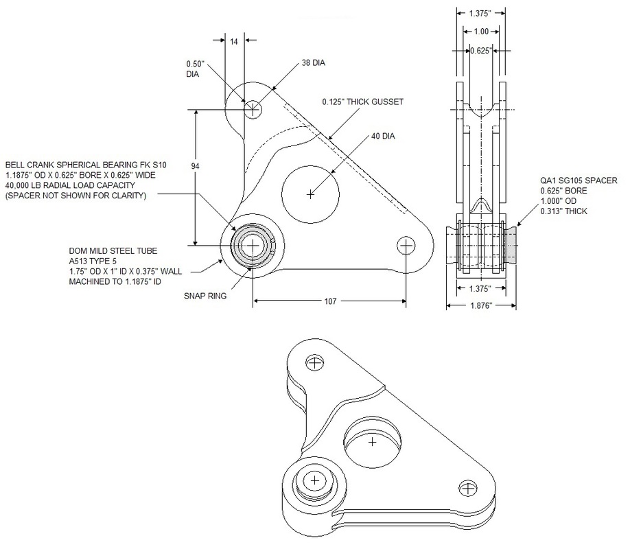
With the bell crank design finalized, I could move on to fabricating it, which is what comes next.

 RSS Feed
