The shock absorbers I mentioned in the previous post are made by QA1. They are Proma Star aluminium-bodied coil-overs with 18 position external single adjustability. I bought them through Summit Racing (P/N: HAL-DS501) and got external dimensions and range of operation information from the internet. That allowed me to add them to my collection of drawings:
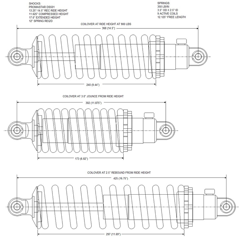
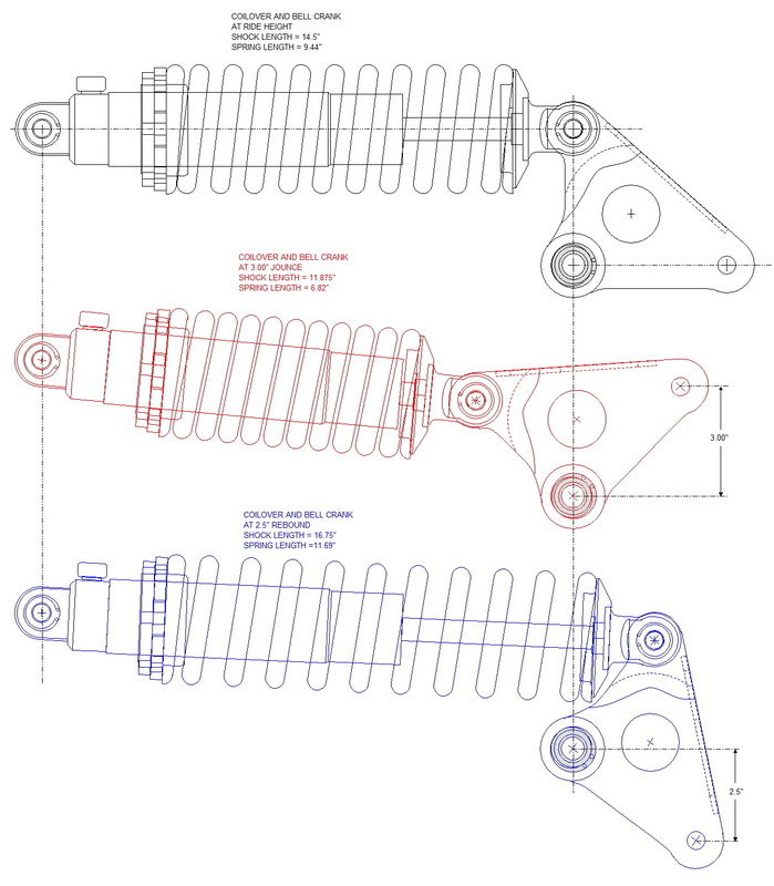
I chose 12" long 350 lb/in springs which led to them being compressed 2.56" at ride height when I assumed a 900 lb weight distribution at each rear corner. I then added them to my bell crank drawing and simulated the position of the shock, bell crank, and spring at ride height, 76 mm (3.0") of jounce, and 63.5 mm (2.5") of rebound:
I then scaled the bell crank and coil-over to my earlier chassis drawings, and added them so the lower end of the bell crank was aligned with the top of the knuckle. Then I filled in the voids to create suitable mounts for the bell crank and coil-over. It was a lot more work than these words convey, but here is the final rear suspension configuration along with some notes describing the various components:
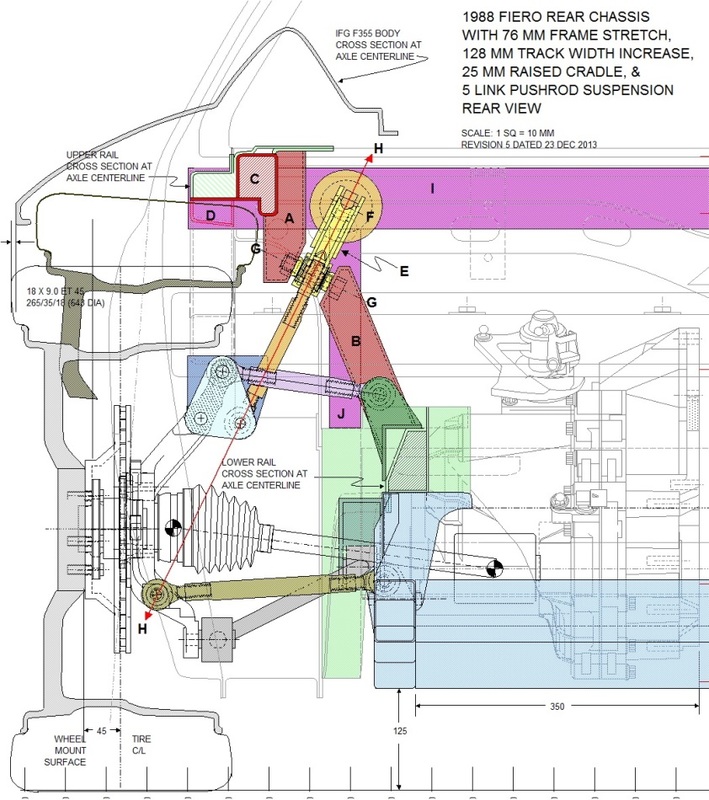
Of the three different views I'll be posting, the rear view is the most revealing. The upper and lower crank mounts (A & B) are the most clear in this one... they're just capped off 2" x 3" x 1/8" wall rectangular tubes. The upper mount drops down from a new upper frame rail stiffener (C). There are a few things to note about this area so I've broken them down into the following sub-paragraphs:
1. you can clearly see how the original cross section of the upper frame rail has been modified. I've left a barely visible outline of the part that was removed (D) just to show what it used to look like. I've also drawn an outline of the wheel and tire at full jounce (76 mm) to show why it was necessary to notch the bottom of the rail;
2. the stiffener (C) will serve as the main anchor point for the upper bell crank mount (A). The top of the mount will also be welded to the underside of what's left of the old strut tower. That portion of the strut tower is made up of two heavy gauge steel plates welded together;
3. the rear view also shows how the bell crank (E) and coil over (F) clear the mounts side to side and from the bottom. I had to square off the top corner of the lower crank mount (B) since the aft end of the coil-over angles downward by about 20 mm in full rebound and would otherwise have contacted the top of the mount;
4. to tighten the bell crank bearing bolt, the bell crank mounts will have an angled access hole (G) cut in one wall large enough to get a socket wrench on the nut and bolt;
5. the angle of the bell crank and pushrod wasn't just arbitrarily chosen. Notice how a line (H) drawn though the centre of the crank down through the lower end of the push rod lines up perfectly with the outboard lateral link pivot. Having these parts line up this way ensures a 1:1 ratio between the wheel movement and the pushrod movement... i.e. 1" upward movement of the wheel translates into 1" upward movement of the pushrod (Of course I reduced the ratio of the motion actually transmitted to the shock with the non-equal length arms on the bell crank); and
6. lastly, if you recall from Post #33, I planned to add an upper cross car brace (I) under the rear window. The plan is to use that brace to mount the stationary end of the shocks, the engine torque struts, and the deck lid hinges. I planned to run the drop down supports (J) vertically to the lower frame rail. They are directly aligned with the stationary coil-over mount, giving the area better strength to react the spring's forces.
Tired of reading? You should try typing this stuff out. OK, on to the side view to see what gems might be hiding there:
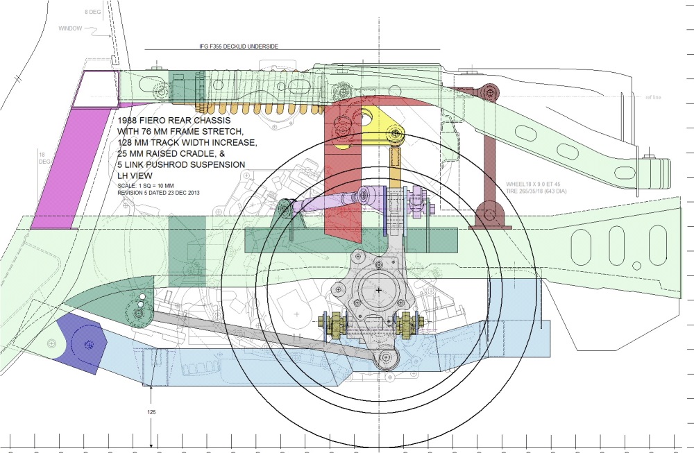
In this view you get a better idea how the vertical supports for the cross car brace (fuchsia) are anchored to the lower frame rail, and despite being mostly hidden by the upper frame rail, you can also see how the stationary coil-over mounts project backwards to meet up with the shock.
You can also see how the coil-over is at the same height as the upper frame rail (well-below the deck lid). This keeps the forces exerted on the cross car brace in the same plane as the main structures that react them. It just means that the cross car brace will be under a simple bending force rather than a compound bending and torsional force.
Two last tidbits from this view: if you look closely, you'll see the large hole in the upper bell crank mount to provide access to the crank bearing bolt with a socket wrench I mentioned earlier and; for those who haven't fallen asleep yet, you'll notice I've pencilled in an additional pushrod off the crank that leads to a sway bar (brown). For now it's just a concept since I may or may not use a sway bar, but interestingly enough, it appears the stock '88 rear sway bar would fit in that space like a well made glove.
Lastly, the top view is always the most obscured view since everything is layered very much vertically. The view does give a bit of insight into how some of the pieces fit though:
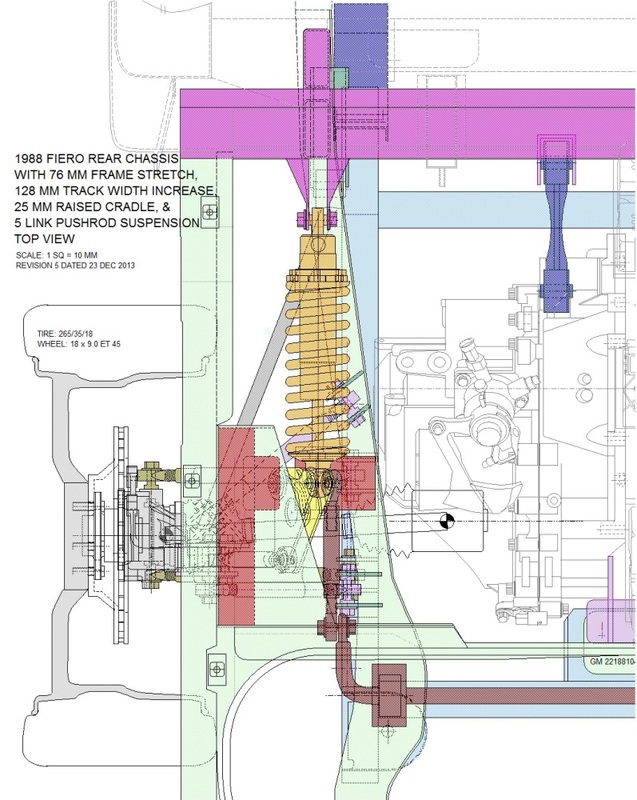
Here, the stationary coil-over mounts are much more visible, as is the shape of the left-over strut tower (light green). I cut out a large portion of the strut tower but left the top piece in a triangular shape to act as a large gusset between the upper frame rail and the old strut tower brace that's integral with the trunk wall. If I do indeed use a sway bar set up like I've pictured here, I might need to replace the old strut tower brace with a different design so as not to interfere with the movement of the sway bar arms.
So there you have it. This pretty much completes the design phase of the rear 5-link suspension.

 RSS Feed
