The next thing on the agenda was to fabricate the bell crank mounts. The available space for the left and right mounts was different with the engine taking up much more room than the transmission on the other side. The solution was one heavy-duty pillar rising up from the lower frame rail and another dropping down from the upper frame rail with the bell crank sandwiched between. The mounts are in blue and the pushrod, bell crank, and shock are in yellow in this rear view drawing:
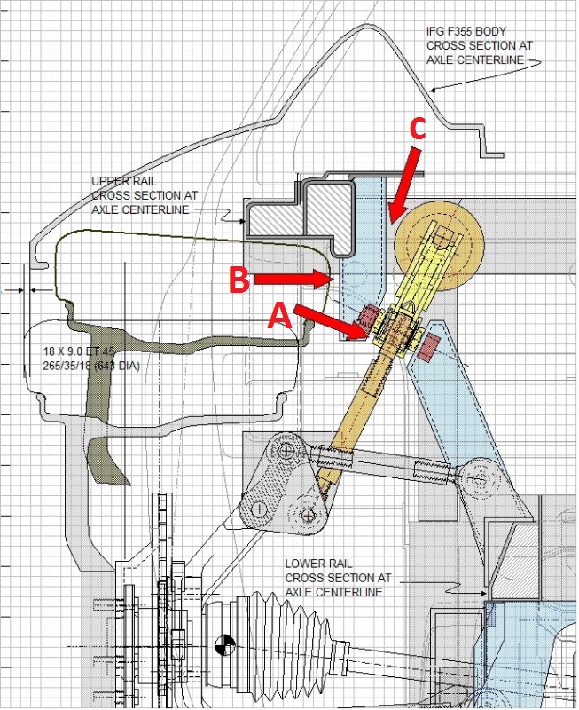
With engine and transmission clearances solved, the first and foremost challenge was to determine a way to ensure the bell crank mounting surfaces would be parallel to each other with the correct gap (arrow A). They also needed to stay clear of the wheel and tire as they moved through the entire range of jounce and rebound (arrow B). And lastly, the design had to ensure it wouldn't interfere with the swinging bell crank nor with the shock & spring either (arrow C). There wasn't a lot of room for error given the tight space.
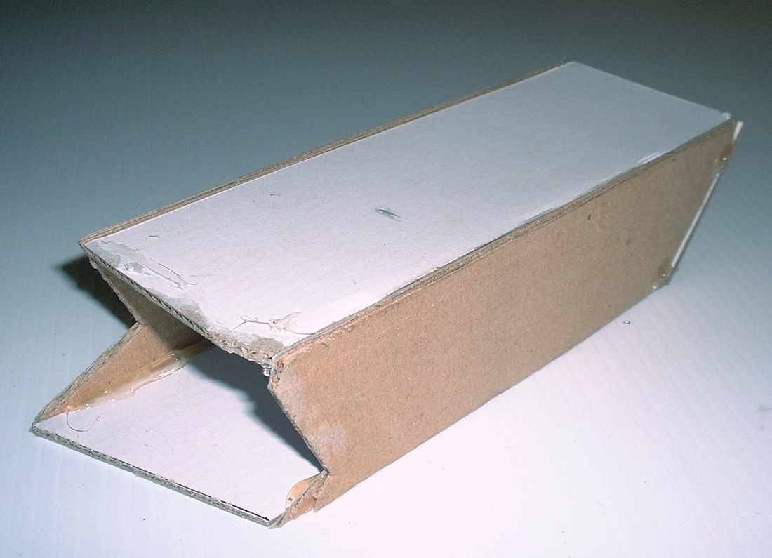
I used some corrugated cardboard to fabricate a 2" X 3" rectangular tube as a template/proof of concept for the lower mount. It was tricky to get the correct shape where it intersected the frame rail because of the compound angles involved, but it worked out pretty well and I only used up about three hot glue sticks and two boxes worth of cardboard.
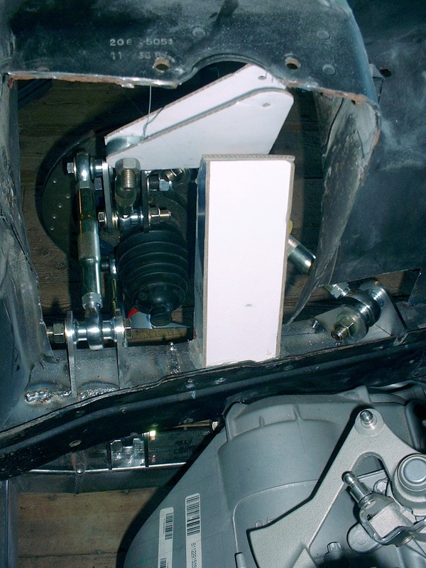
Then I used my cardboard bell crank and bolted it to the top of the pushrod. That allowed me to find and transfer the angle of the bell crank onto the top of the mount and trim it to the right angle and height. Here's the view from the inside of the engine compartment looking out through where the old strut tower use to be:
Once I was satisfied with the fit, I transferred the measurements to a steel 2" x 3" x 1/8" rectangular tube and hacked away at it with the chop saw and the angle grinder until it mated snugly with the frame rail reinforcement I added earlier:
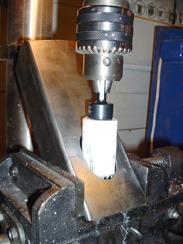
Next, I drilled the 5/8" hole for the bell crank pivot bolt, and then a large hole to be able to access the head of the pivot bolt with a socket wrench:
Then, I carefully aligned the lower mount on the frame rail stiffener and tack welded it into place. It probably took me an hour or more to make sure it was perfectly aligned.
The next step was to temporarily attach the bell crank and get some fine tuned measurements for the shape and location of the upper bell crank mount. So I first attached the steel crank to the top of the pushrod:
Then threaded the bell crank pivot bolt up through the hole in the lower mount and added one of the special spacers I bought just for this purpose:
Then slipped the bell crank onto the pivot bolt and added the second spacer:
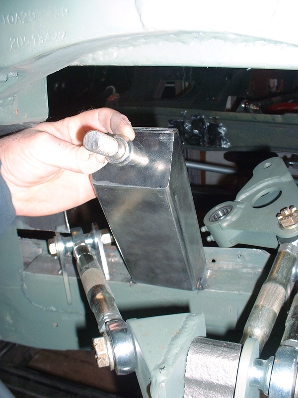
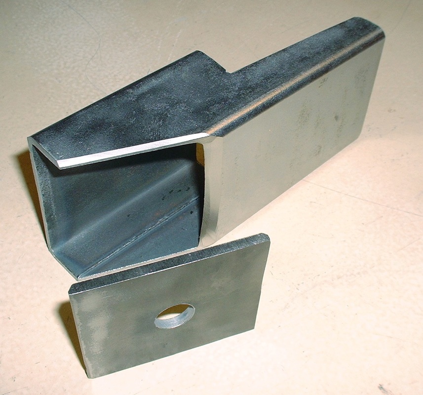
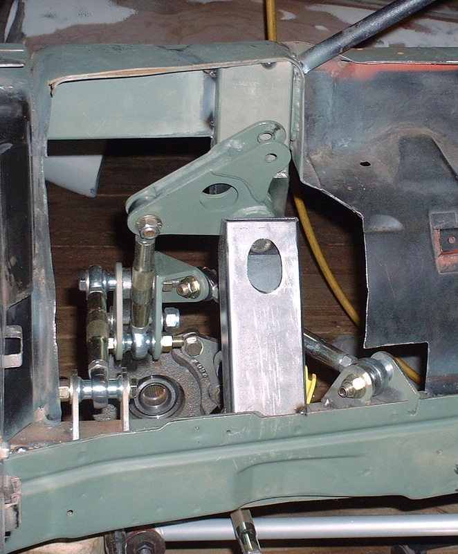
This set the final angle of the bell crank which then allowed me to focus on the upper mount. The upper mount proved to be a bit of a challenge for several reasons. The first was that I had to precisely bridge the space between the upper frame rail reinforcement and the bearing spacer on the bell crank in 3D space. The upper mount had to be made of several pieces so I started by making the rectangular end plate and the body of the main mount slightly oversized in all dimensions:
I then secured the end plate to the bell crank pivot bolt to give me a platform from which I could take better measurements to the upper frame rail:
...and in a slow iterative process I fitted and trimmed the main body portion:
I eventually managed to get it fitted perfectly, so with the main body portion of the mount tightly clamped to the upper frame rail, I tack welded the end plate to the upper mount body:
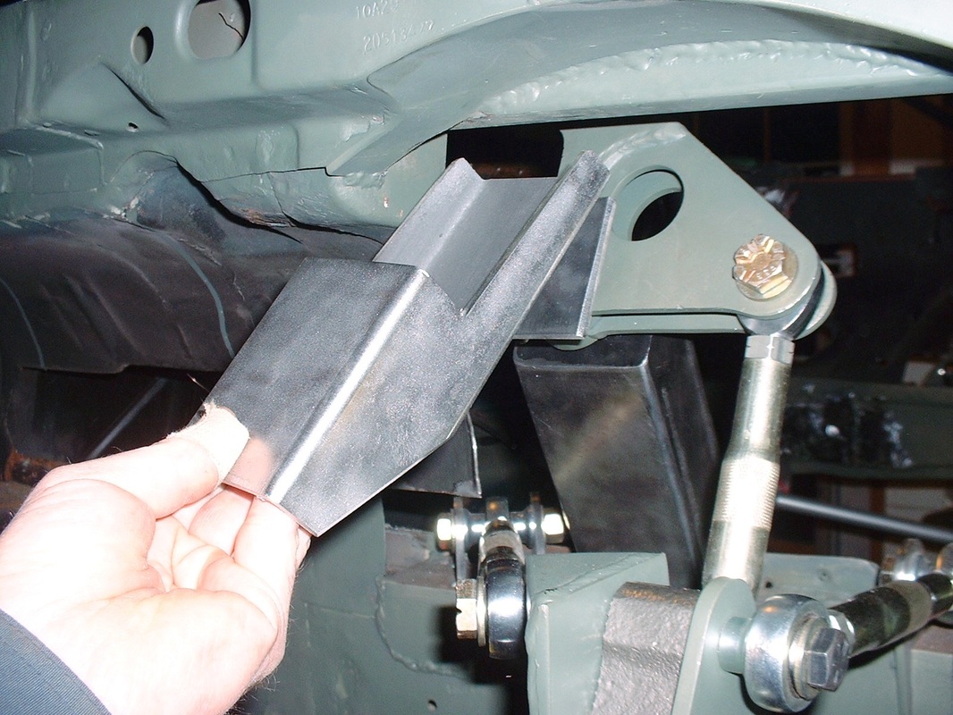
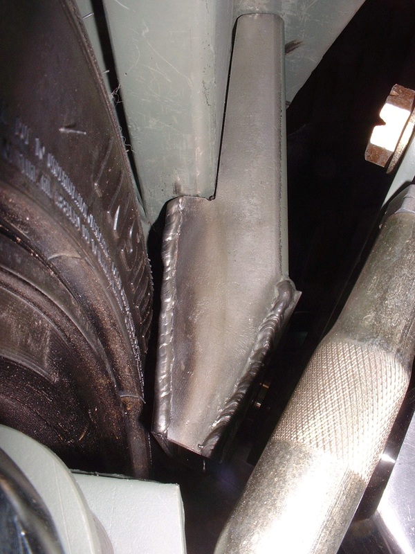
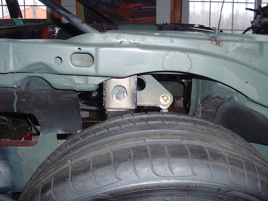
Before I could do the final welding I had to compress the suspension into full jounce and check the clearance between the upper mount and the tire sidewall (arrow B in the drawing above). I found about 5 mm's clearance... which should be enough:
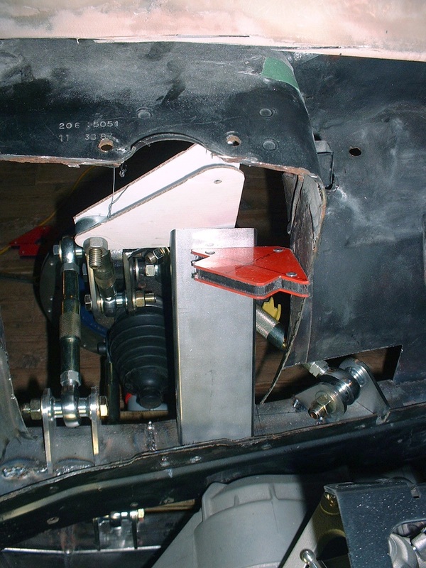
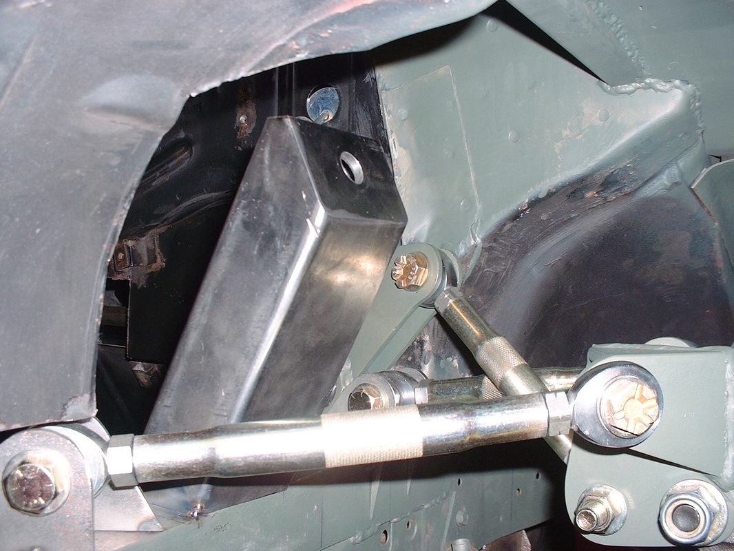
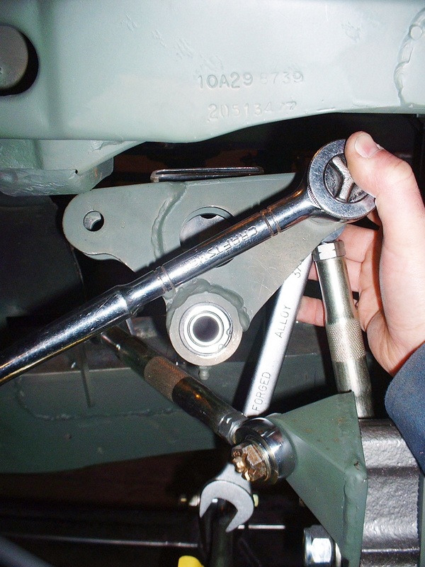
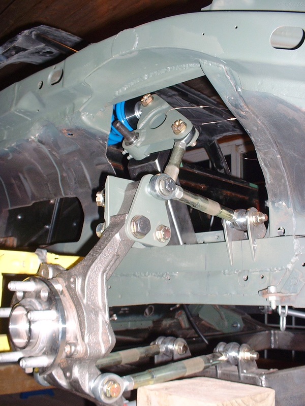
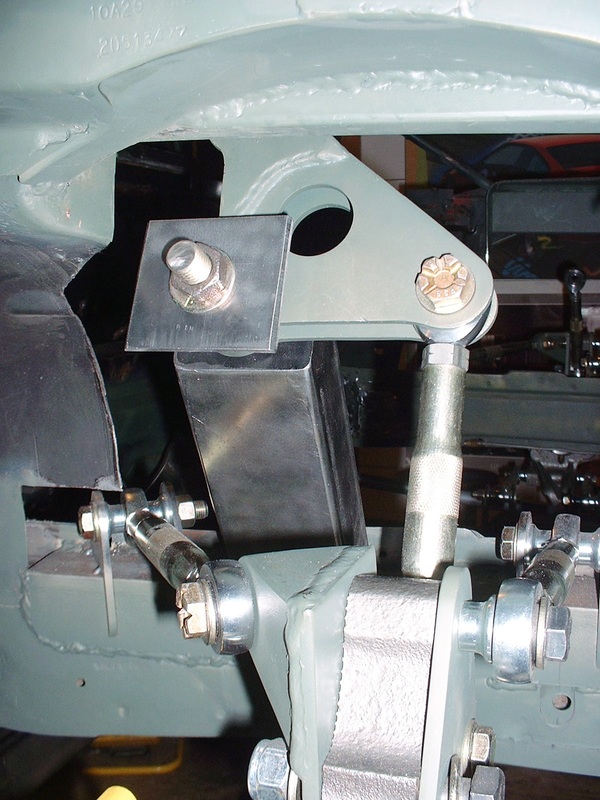
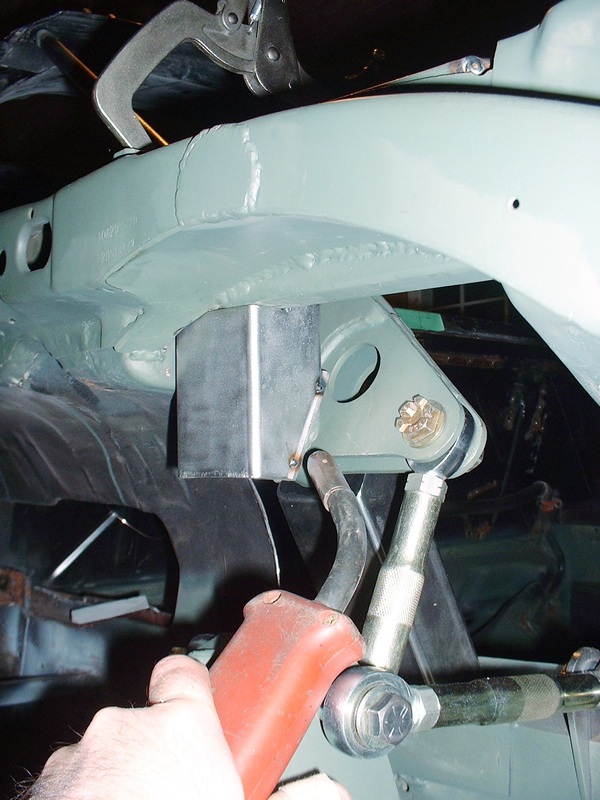
The last modification I had to do to the upper mount was drill an access hole for a socket wrench to be able to tighten the nut on the bell crank pivot bolt. Here's the final configuration from the street side looking inboard:
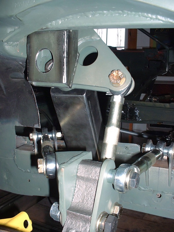
And from the engine bay looking outboard:
Finally, here's what you see when the wheel and tire are reinstalled and the suspension is set at ride height:
Once these photos were taken, I completed the welding and repeated the process for the passenger side mounts.

 RSS Feed
