Now that I've covered some of the work the IFG body kit requires to be presentable, the rest of this section will cover the additional work to finish it off. For convenience, I've divided the work into five more-or-less consecutive phases:
1. Mocking Up;
2. Mounting;
3. Patchwork;
4. Smoothing;
5. Painting
I'll cover the work done to each body panel in separate posts before moving on to the next phase.
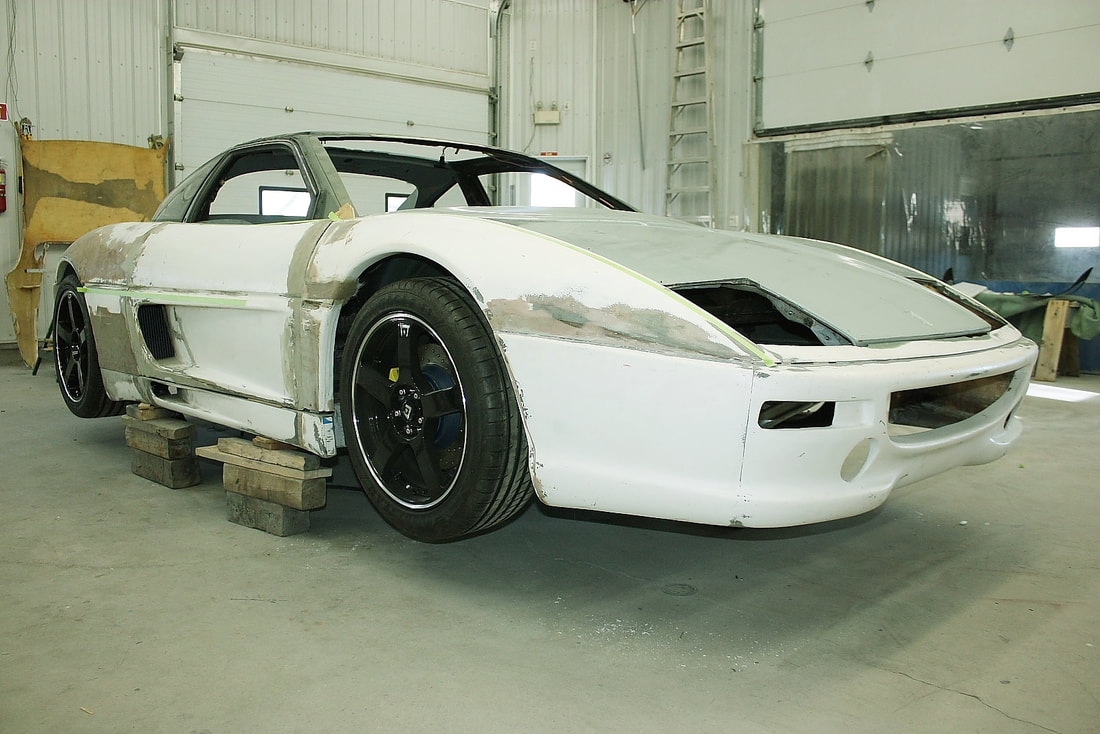
I pretty much finished the Mocking Up phase during the last three posts. I used blocks of wood, shims, Cleco fasteners, and sheet metal screws to temporarily pin each panel in place. The IFG kit has very few mounting points in common with the Fiero body, so most of the initial alignment and spacing was based on trying to hang the parts in mid air. As mentioned before, I started with the rear quarters and made my way forward, reworking the entire body placement several times before accepting a compromise between "best-fit" and "least-work-to-modify".
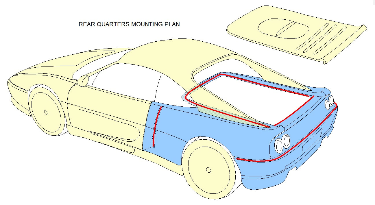
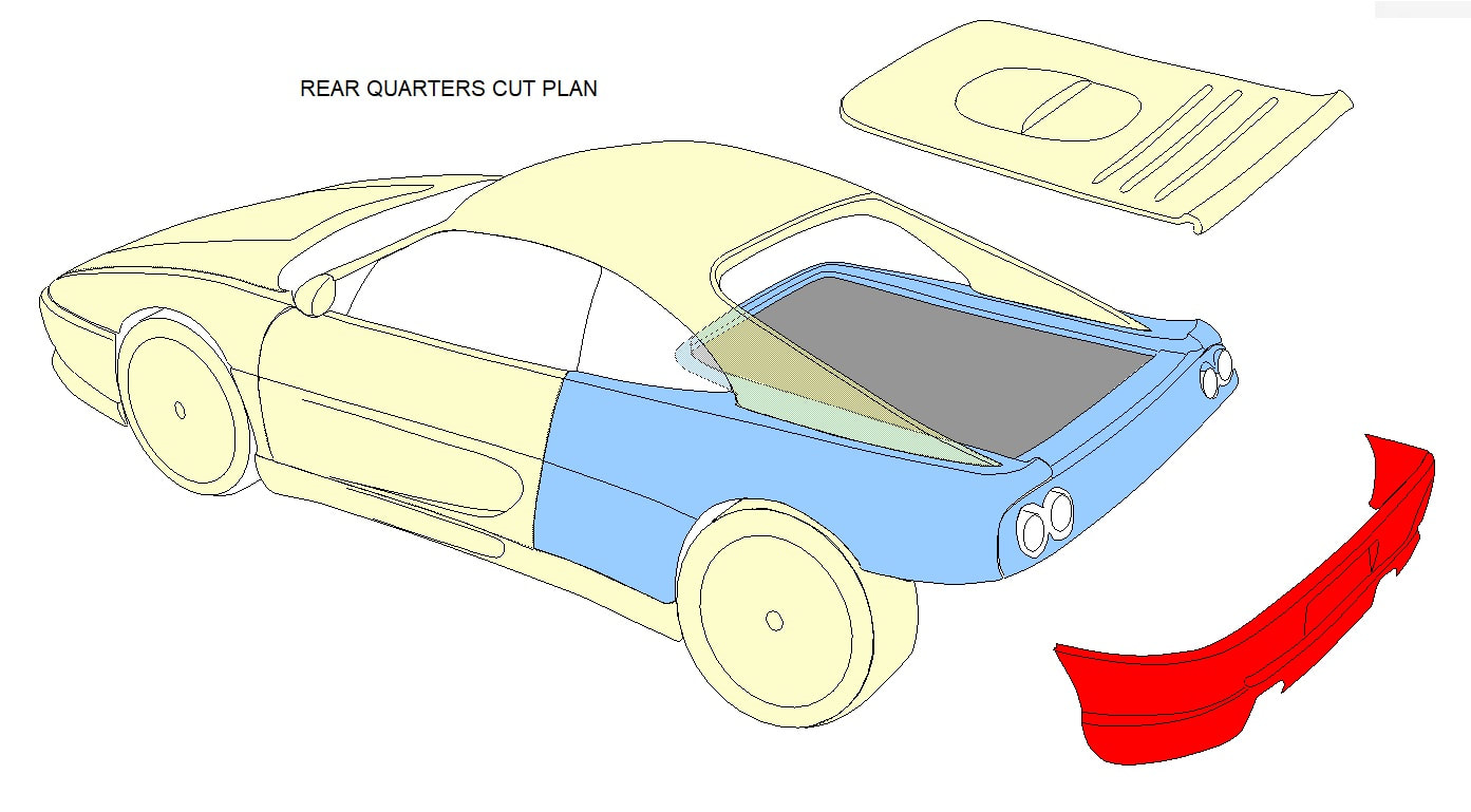
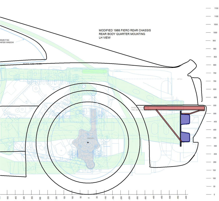
Once I had established the best alignment and placement, I carefully marked the location of the rear quarters in relation to the underlying chassis in several key areas. This would allow me to remove and replace the panel several times while designing a mounting system, yet still reproduce the exact same placement each time. Then I set about planning where and how I'd mount the rear quarters. The red lines in the drawing below show the primary support structures I settled on:
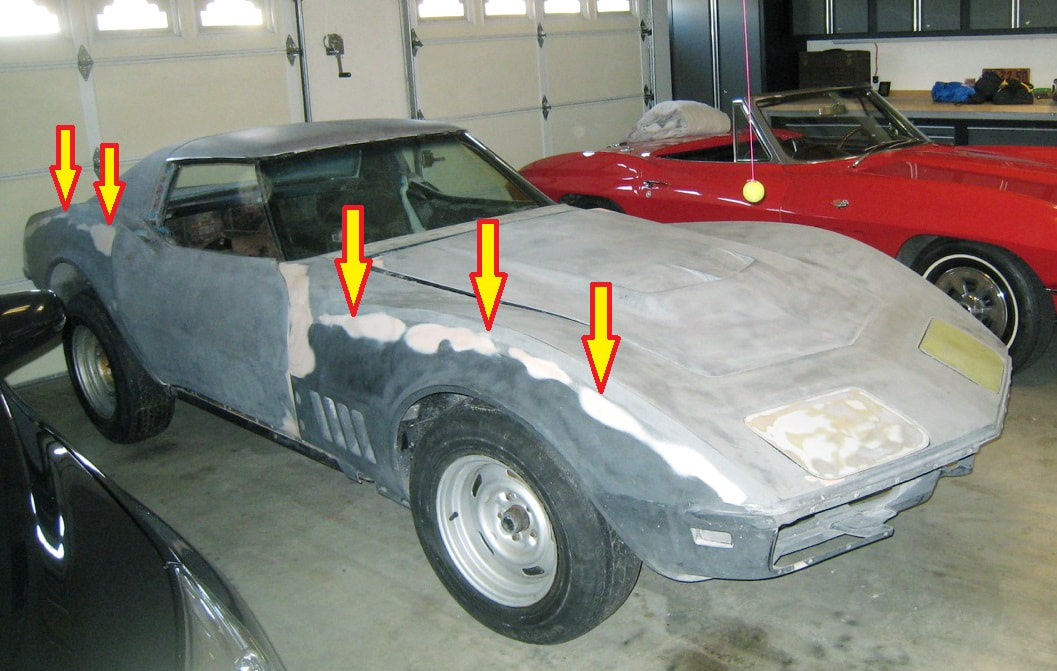
On the advice of my body shop, I avoided supporting the quarters under the middle of any exterior panels. Anyone with a C3 Corvette knows how the adhesion line to the underlying structure shows up through the fibreglass fenders after a couple years of differential expansion and contraction:
On the advice of my body shop, I avoided supporting the quarters under the middle of any exterior panels. Anyone with a C3 Corvette knows how the adhesion line to the underlying structure shows up through the fibreglass fenders after a couple years of differential expansion and contraction:
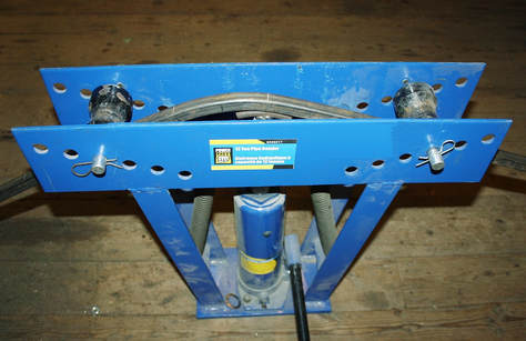
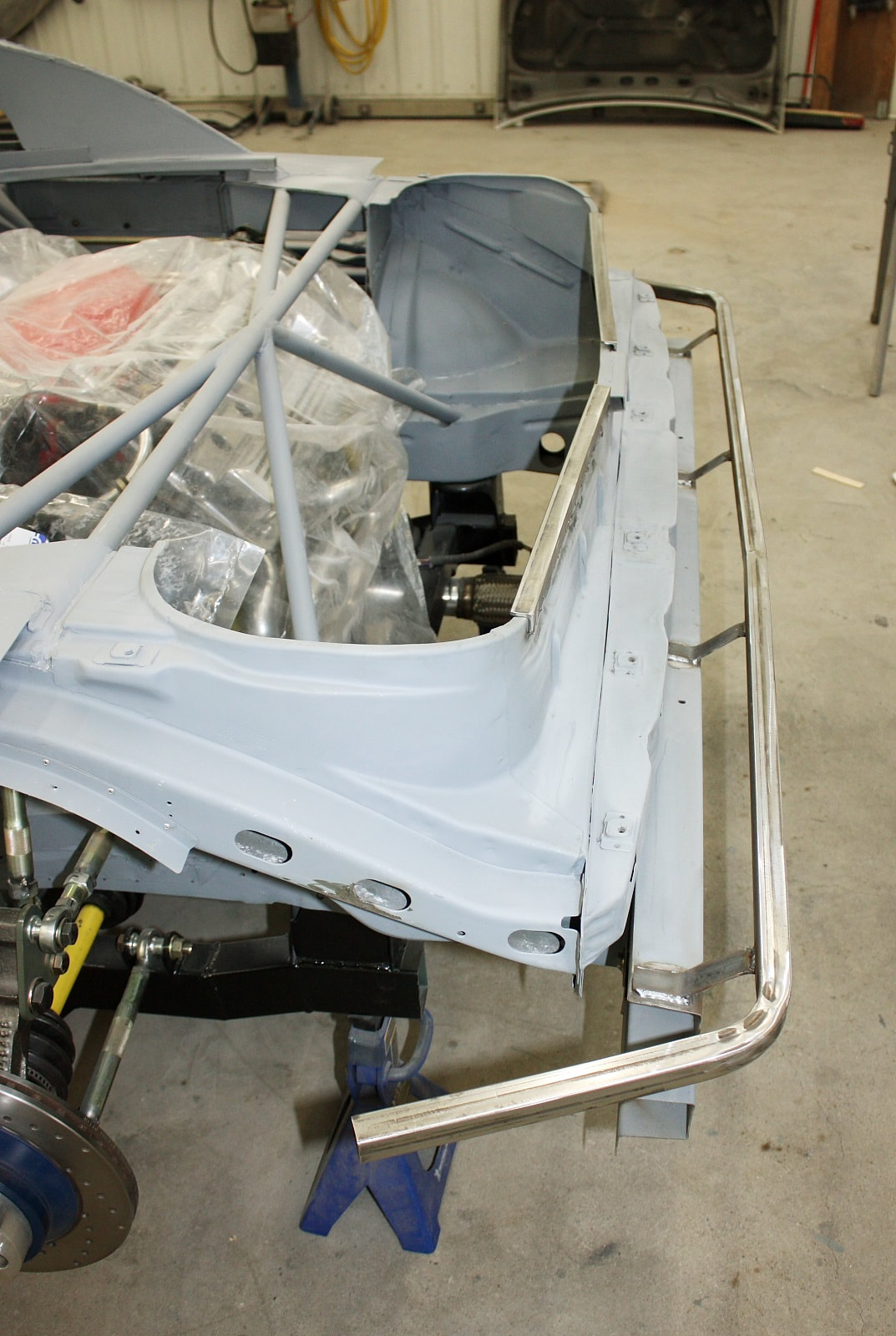
I started by fabricating the support under the rear fascia. I used 1" square tubing with 1/8" wall thickness, and bent it with the same die and pipe bender I had used earlier for my rear window frame:
 |  |
With the rear quarters off the car, it was a cinch to bend the tubing a little at a time, testing the fit to the inside of the fascia and making further adjustments as necessary. I don't have any good photos of the tubing sitting in place, but I'm sure it's easy to imagine.
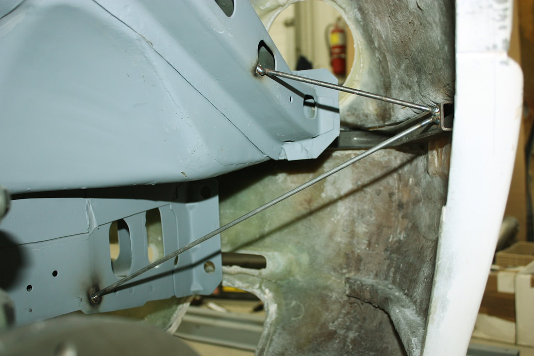
Once the tubing fit correctly, I clamped it to the inside of the fibreglass and reinstalled the rear quarters. That placed the tubing in the correct location relative to the chassis, so I welded some temporary rods between the tubing and the chassis in the few places I could access. This next photo is taken from inside the rear wheel well looking backwards:
Most of the fascia support tube across the rear of the car was inaccessible with the quarter panel in place, so I couldn't properly brace the tube to the chassis without taking an intermediary step. Taking the entire rear quarter panel off was out of the question since it would have had to be tilted, and the "legs" on the new tube wouldn't allow that. So I moved onto "Plan B":
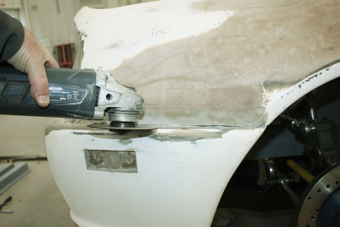
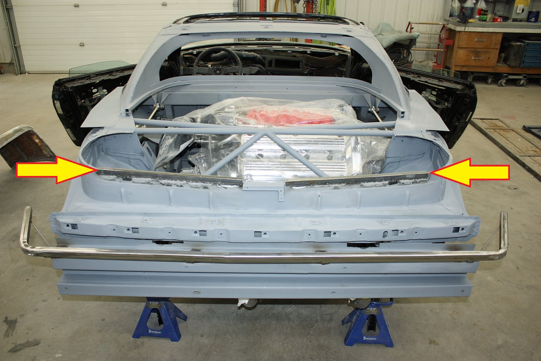
I wanted a removable rear fascia anyway, so after carefully marking out a perfectly level line with the laser level, out came the angle grinder with a thin cut-off wheel, and off came the fascia:
The detachable fascia is handy for four reasons: the look... the authentic Ferrari has a separate fascia; the protection... a minor rear collision will stress only the fascia, not the quarters and sail panels; the ease of fascia repair; and accessibility to rear mounted systems for maintenance:
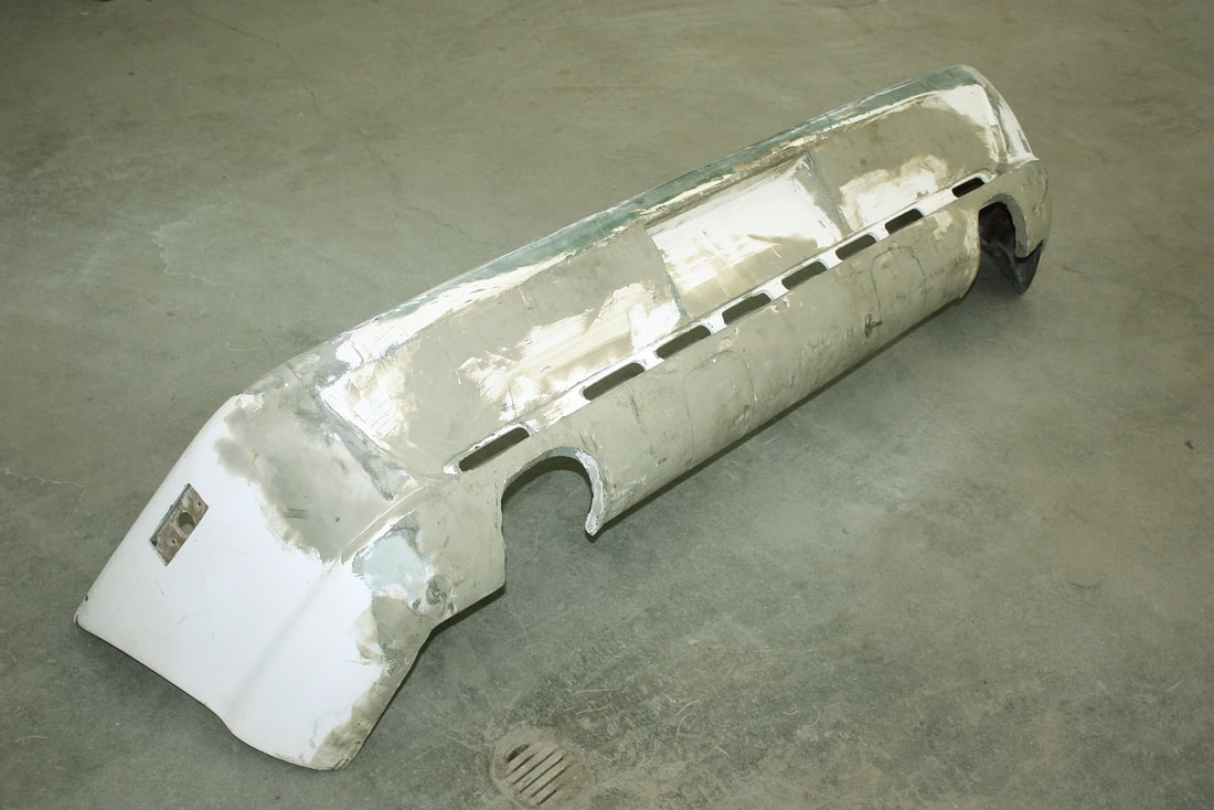
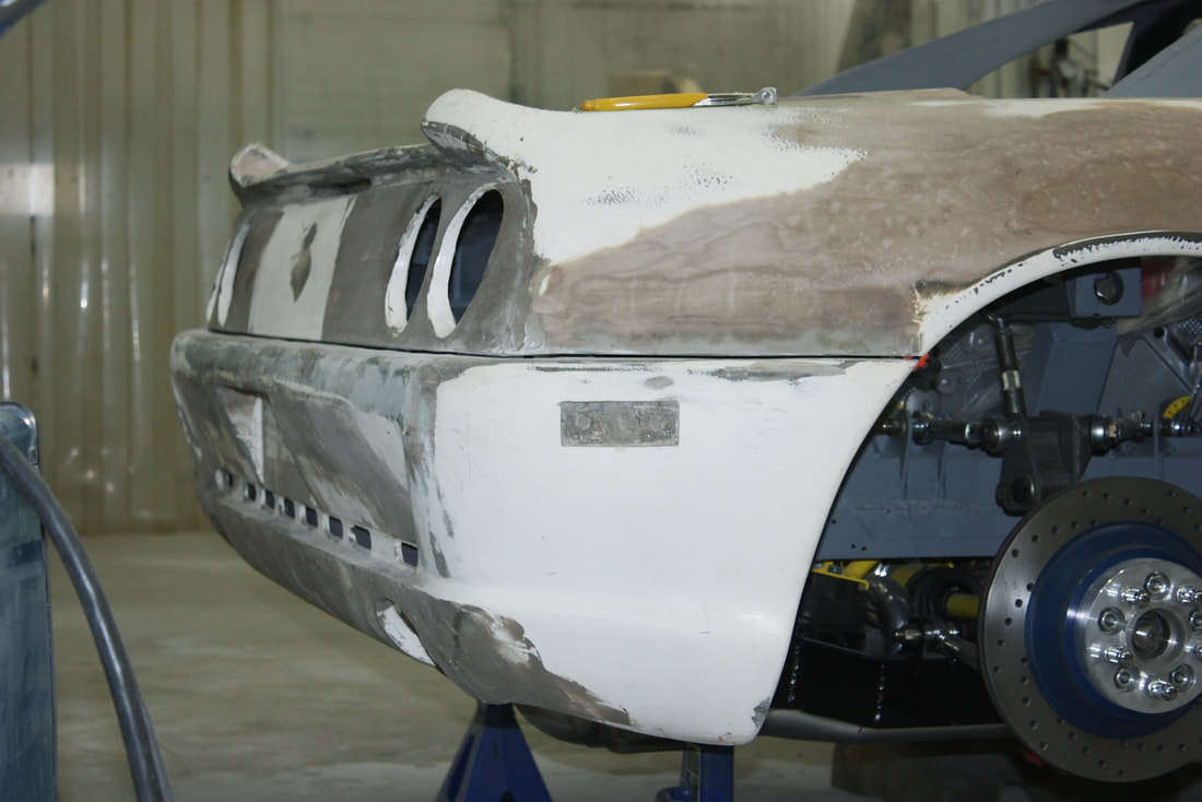
Here's what the rear quarters looked like after the rear fascia was removed:
One final reason for separating the rear fascia from the quarters was to address a misalignment between the fascia and the quarters right from the IFG mould. With the one-piece rear quarters, levelling the cross-car line along the top of the taillight panel resulted in the fascia being tilted downward on the left by about 5/16" from one side to the other. Noticeable to the naked eye. In this next photo, I've drawn a black line showing how much of the light panel needed to be trimmed off the left side to bring the fascia horizontal:
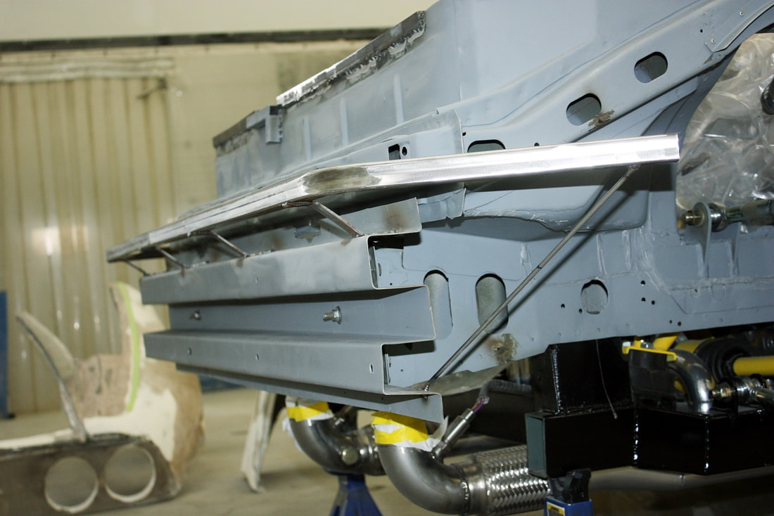
The square tubing stayed neatly in place with my temporary braces, and without the rear fascia in the way, I could start planning the permanent braces. With a little forethought, I decided to attach the fascia support tube (red) to the rear bumper bar (blue) rather than directly to the frame. This way, the fascia would retain some adjustability, since the bumper bar is held to the frame horns with oversized bolt holes:
Using some 1" x 1/8" flat steel, I cut and formed four Z-shaped braces and welded them between the fascia support and the bumper bar:
Then I removed the temporary braces and welded two 3/16" diameter rods to triangulate each of the support's legs. Here only one rod is visible:
At this point, I also took the opportunity to weld a couple lengths of angle iron to the Fiero aft trunk seal flange, completing another step in my rear quarters mounting plan:
I then test fitted the rear fascia back on the chassis, fully supported by the new support bar:

 RSS Feed
