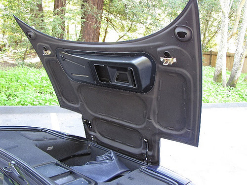
The last piece of hood hardware I needed to figure out was a means to hold it open. The Fiero has a telescoping and latching prop rod, but it would be a dead giveaway if I were to use it. Besides, what manufacturer would produce a six-figure car and cheap-out with a manual prop rod? Here’s the authentic car’s open hood:
The last piece of hood hardware I needed to figure out was a means to hold it open. The Fiero has a telescoping and latching prop rod, but it would be a dead giveaway if I were to use it. Besides, what manufacturer would produce a six-figure car and cheap-out with a manual prop rod? Here’s the authentic car’s open hood:
And here’s a close up of the gas springs from a friend’s F348, which is identical:
And here’s a close up of the gas springs from a friend’s F348, which is identical:
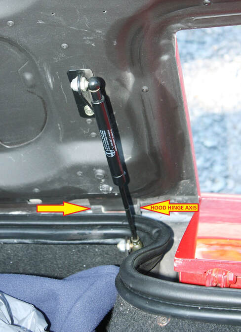
The key design features are that the spring is entirely inside the weather-tight front compartment, the lower ball joint is further back and lower than the hood hinge axis, and the upper ball joint is attached to a bracket that appears to drop away from the under surface of the hood by an inch or so.
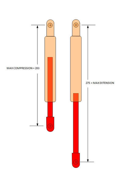
The other key piece of info is the gas spring part number. Looking that up sent me to the Stabilus web page and this drawing:
The key design features are that the spring is entirely inside the weather-tight front compartment, the lower ball joint is further back and lower than the hood hinge axis, and the upper ball joint is attached to a bracket that appears to drop away from the under surface of the hood by an inch or so.
The other key piece of info is the gas spring part number. Looking that up sent me to the Stabilus web page and this drawing:
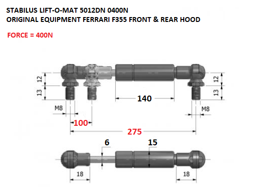
The really important info here is in red, with the spring force being 400N (88 lbs) and the max and min dimensions of the pushrod travel. If Ferrari could make these springs work, then they’d probably be pretty close to what would work with my hood.
The next steps were to figure out if there was enough physical space for them on my car; figure out the correct geometry for them to do more than simply look nice; and calculate whether 400N would be the right amount of force. So I took out my handy scale drawings of the hinge area, and began laying out some ideas. This first drawing shows how little room there is between the spare tire well and the headlight, and that if I wanted to mount the springs in line with the hinges, I’d need some additional structure:
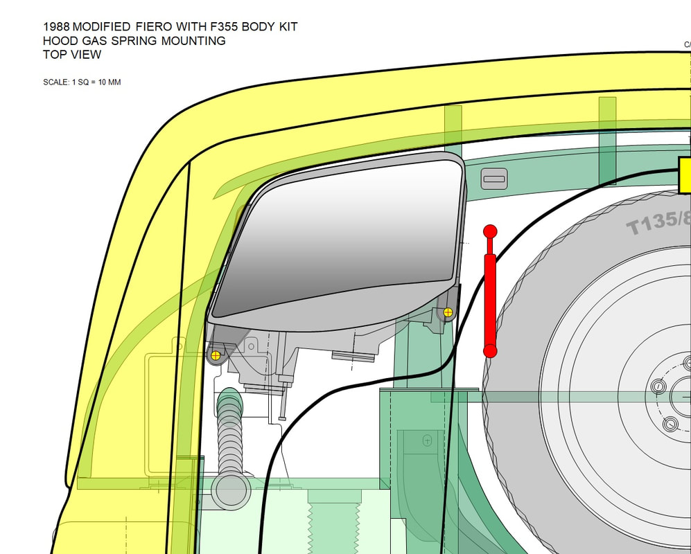
In the drawing above, I’ve erased the layers of surrounding sheet metal to expose the structures near the gas springs, namely, the lower frame horn to the left, and the front rebar. The thin sheet metal of the front compartment wouldn’t be stiff enough to resist the forces without bending or warping. I had to consider reinforcing the mounting area for the springs.
The second thing that jumped out was that I’d need to redesign the front compartment wall.
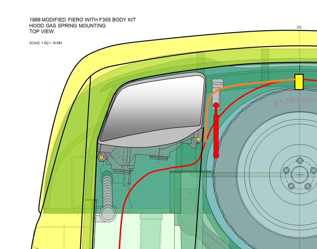
The thin red line in the drawing above shows the current routing of the compartment wall, and the orange line shows where it would need to go to prevent the spring from interfering with the weather seal and wall.
With these considerations in hand, I played around with the side view drawing until I found a physical orientation of the gas springs that achieved two goals:
- a large portion of the total spring travel was used between fully open and fully closed (some orientations don’t result in any extension or compression at all!); and
- whenever fully open or fully closed, the orientation of the gas spring was close to being parallel to the plane of the hood. (This last criteria is important especially in the closed position because if the gas springs are installed so they end up perpendicular to the hood, they’ll apply a large bending force, between the hinge and the latch, which will typically warp the closed hood unless it’s very rigid.)
So here’s what I came up with, mimicking the F355’s design:
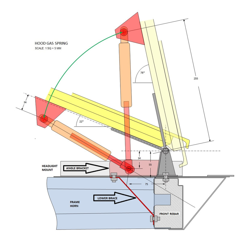
The parts in red and orange are the newest parts. I wanted to align the gas spring in the fore and aft direction with the hinge to keep the spring forces from twisting the hood, so I added a steel angle bracket (see upper arrow) to the lower part of the hinge that extended straight back. Then, since the new angle bracket was cantilevered out in space, I added a lower brace (see lower arrow) underneath it to triangulate it back to the front rebar.
The upper mounting point was chosen to optimize the spring travel. In the end, I was able to make my design compatible with the authentic F355 gas springs from a geometric perspective, in other words: less than 100 mm total travel, and max extension at 275 mm:
With the physical layout sorted out, I then needed to confirm whether the 400 Newton Ferrari springs would be strong enough to hold my hood open. To do that, I created a simple force diagram showing the angles of the hood, and the forces the gas springs and gravity would exert on it. I already knew the total spring force, but I had to estimate the force of gravity by weighing the bare outer skin and doubling it to account for the finished assembly with inner liner, fillers, and paint. I came up with an estimated final weight of 230N (50 lbs).
But in a hinged system like this, only the portion of the gravity and spring force perpendicular to the plane of the hood actually work to swing the hood open or closed. That’s why you can effectively balance an open hood straight up and down on a hinge. So to calculate the portion of the forces working to swing the hood open or closed, I used high school trigonometry and broke down the spring and gravity forces as shown below:
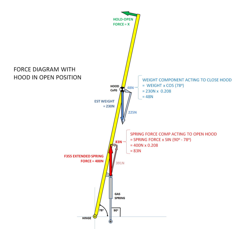
From gravity, only 48 Newtons are in the direction to close the hood, and 83N of spring force (per spring) are forcing it open. Unfortunately, it isn’t a matter of simply subtracting the two forces from each other to arrive at the total force holding the hood open. Since both forces operate at different distances from the hinge, the weight has much more leverage than the springs. To account for their different leverages, the two forces must be converted into moments by multiplying them by their respective distances from the hinge, like so:
From gravity, only 48 Newtons are in the direction to close the hood, and 83N of spring force (per spring) are forcing it open. Unfortunately, it isn’t a matter of simply subtracting the two forces from each other to arrive at the total force holding the hood open. Since both forces operate at different distances from the hinge, the weight has much more leverage than the springs. To account for their different leverages, the two forces must be converted into moments by multiplying them by their respective distances from the hinge, like so:
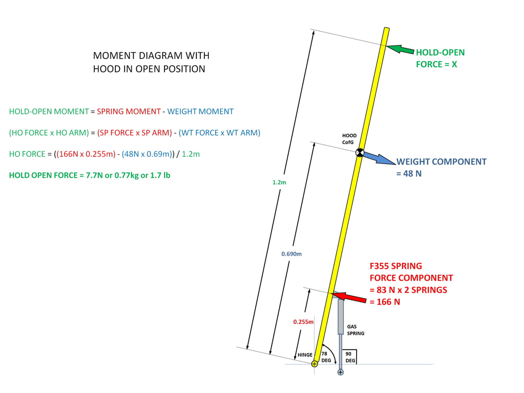
Moments can then be added and subtracted directly from each other, and in this case, the F355 springs would only just hold the hood open. It would take only 1.7 pounds of pressure exerted at the back edge of the hood to overcome the force of the springs to close it.
Next, I needed to determine how heavy the hood would feel trying to lift it from a closed position. Using the same technique as before, I drew a force diagram with the hood closed:
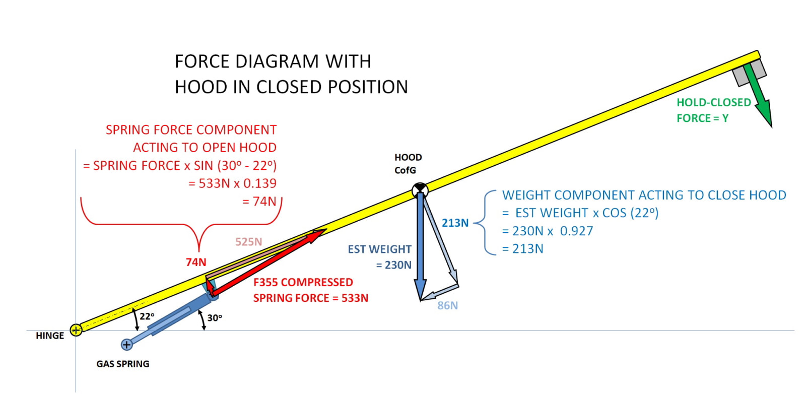
The detail that many might overlook in this calculation is that gas springs are rated for the amount of force the produce when fully extended. When compressed, gas springs exert about 1.33 times the rated force. That’s why in the above diagram the same F355 springs as before now produce 533N each rather than 400N.
Following through with the calculation of the moments resulted in the following:
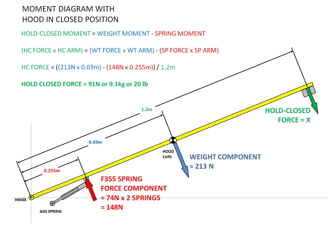
From the diagram above, it would take about 20 pounds to lift the hood from closed. That seemed like a lot, but then I tested the hood opening force on my 13 year old Chevy Trailblazer and my late model Dodge Ram using a handheld spring scale and came up with 20 lbs and 11 lbs respectively. So I’d be within the industry norm if I used the stock F355 springs.
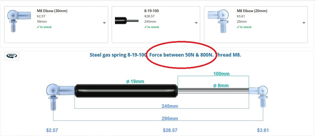
All of these calculations however are based on an estimated weight of the hood. So rather than order up some F355 gas springs, I decided to wait and order precisely what I would need. I discovered that I could order off the shelf springs from www.gasspringshop.com with the same dimensions as the stock F355, anywhere from 50N to 800N for about $30 each:
From the diagram above, it would take about 20 pounds to lift the hood from closed. That seemed like a lot, but then I tested the hood opening force on my 13 year old Chevy Trailblazer and my late model Dodge Ram using a handheld spring scale and came up with 20 lbs and 11 lbs respectively. So I’d be within the industry norm if I used the stock F355 springs.
All of these calculations however are based on an estimated weight of the hood. So rather than order up some F355 gas springs, I decided to wait and order precisely what I would need. I discovered that I could order off the shelf springs from www.gasspringshop.com with the same dimensions as the stock F355, anywhere from 50N to 800N for about $30 each:
Having confirmed that there was enough room physically for a pair of gas springs, and that springs were commercially available in the size and strength I would need, I carried through to the construction phase.
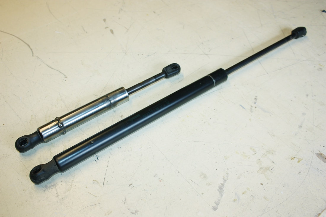
The first thing I did was modify a pair of old gas springs from my Trailblazer’s lift gate for mock-up purposes. I carefully released the residual pressure by drilling a small hole in each one, shortened the cylinders and pushrods, then rewelded the cylinders together again:
Having confirmed that there was enough room physically for a pair of gas springs, and that springs were commercially available in the size and strength I would need, I carried through to the construction phase.
The first thing I did was modify a pair of old gas springs from my Trailblazer’s lift gate for mock-up purposes. I carefully released the residual pressure by drilling a small hole in each one, shortened the cylinders and pushrods, then rewelded the cylinders together again:
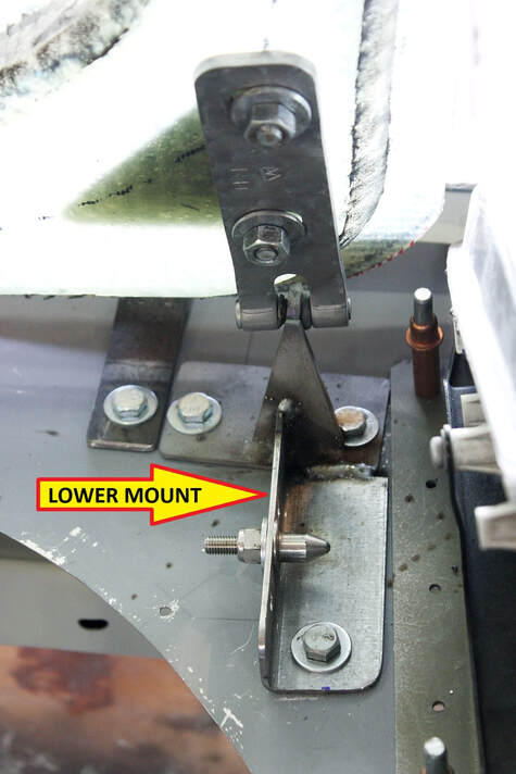
Next, I cut up some steel angles and welded them to the base of the hinges to form the lower spring mounts. I didn’t have a spare set of ball joints, so I made temporary ones out of some alignment pins:
Next, I cut up some steel angles and welded them to the base of the hinges to form the lower spring mounts. I didn’t have a spare set of ball joints, so I made temporary ones out of some alignment pins:
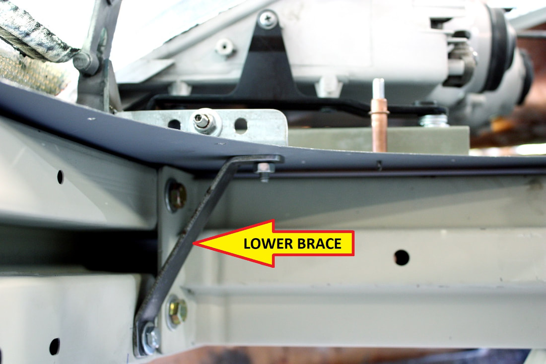
As mentioned before, the lower mounts rather hang out over thin sheet metal so triangulating them to the rebar was next:
As mentioned before, the lower mounts rather hang out over thin sheet metal so triangulating them to the rebar was next:
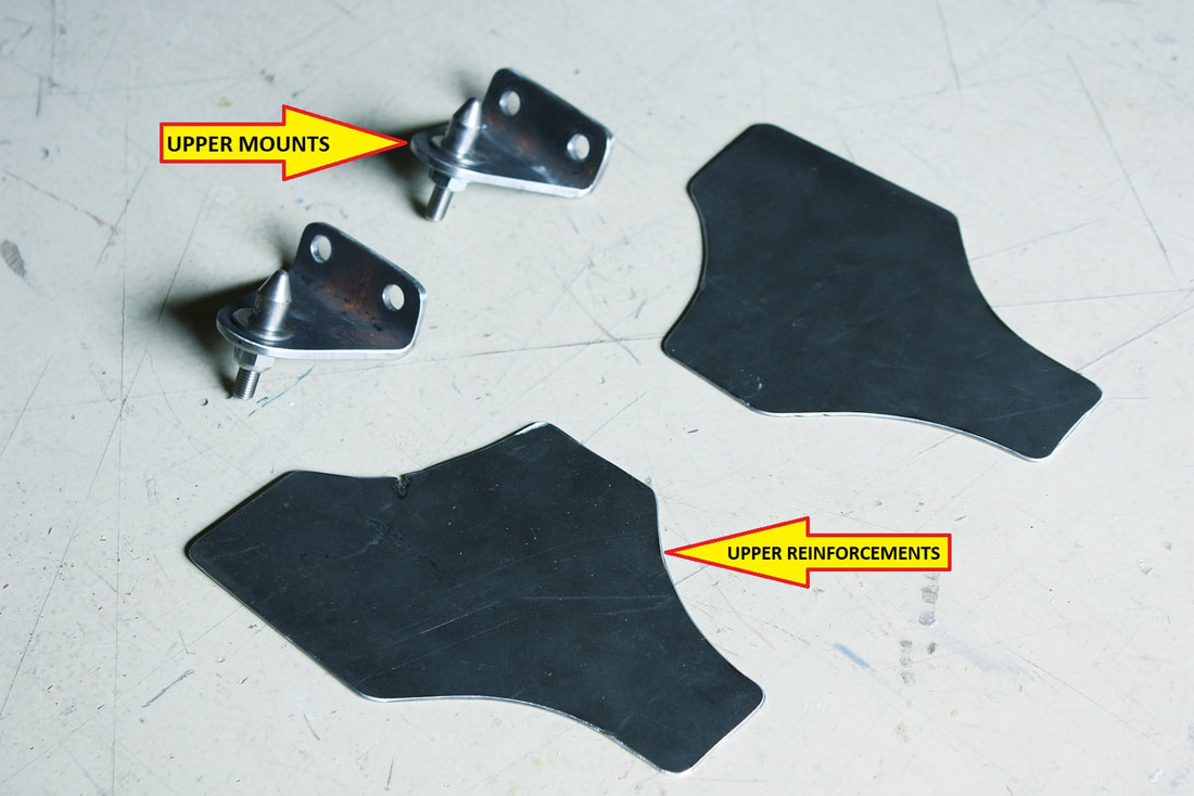
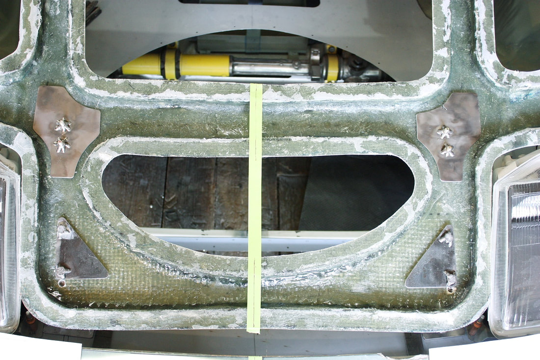
The upper spring mounts were fabricated from 3/16” thick steel angle, drilled and shaped to size. I also made some reinforcement plates for the upper mounts to spread the loads of the springs over a larger area of the webbing:
The upper spring mounts were fabricated from 3/16” thick steel angle, drilled and shaped to size. I also made some reinforcement plates for the upper mounts to spread the loads of the springs over a larger area of the webbing:
I clipped the mock-up springs onto the lower pivots, then the upper mounting brackets to the tops of the springs, extended the springs to 275 mm, and rotated them up to mark the upper mounting locations on the web:
I clipped the mock-up springs onto the lower pivots, then the upper mounting brackets to the tops of the springs, extended the springs to 275 mm, and rotated them up to mark the upper mounting locations on the web:
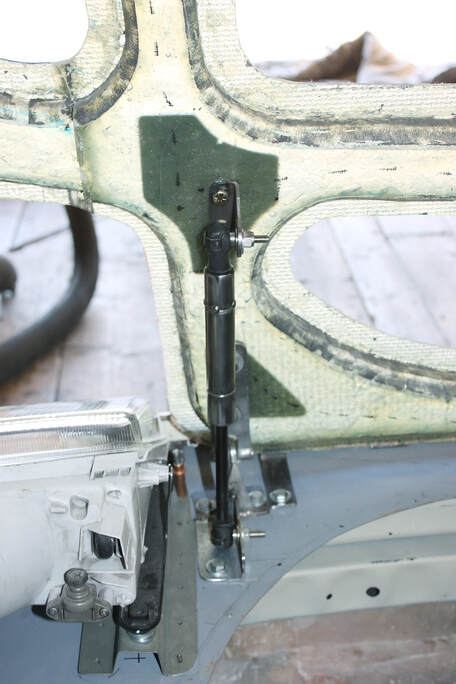
Finally, using the sun's rays to see through the underhood webbing, I located and drilled the reinforcement plates for the upper mounts. They’ll be ‘glassed into the webbing along with all the other reinforcements:
Finally, using the sun's rays to see through the underhood webbing, I located and drilled the reinforcement plates for the upper mounts. They’ll be ‘glassed into the webbing along with all the other reinforcements:
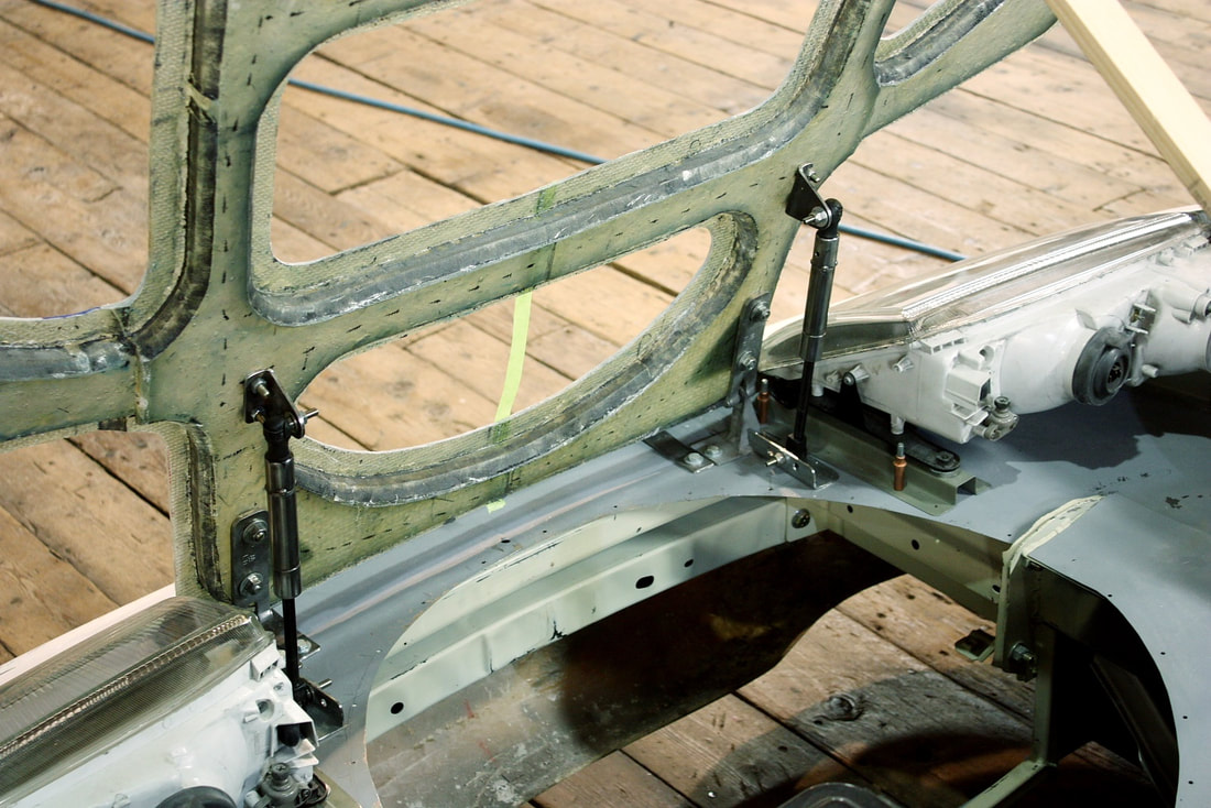
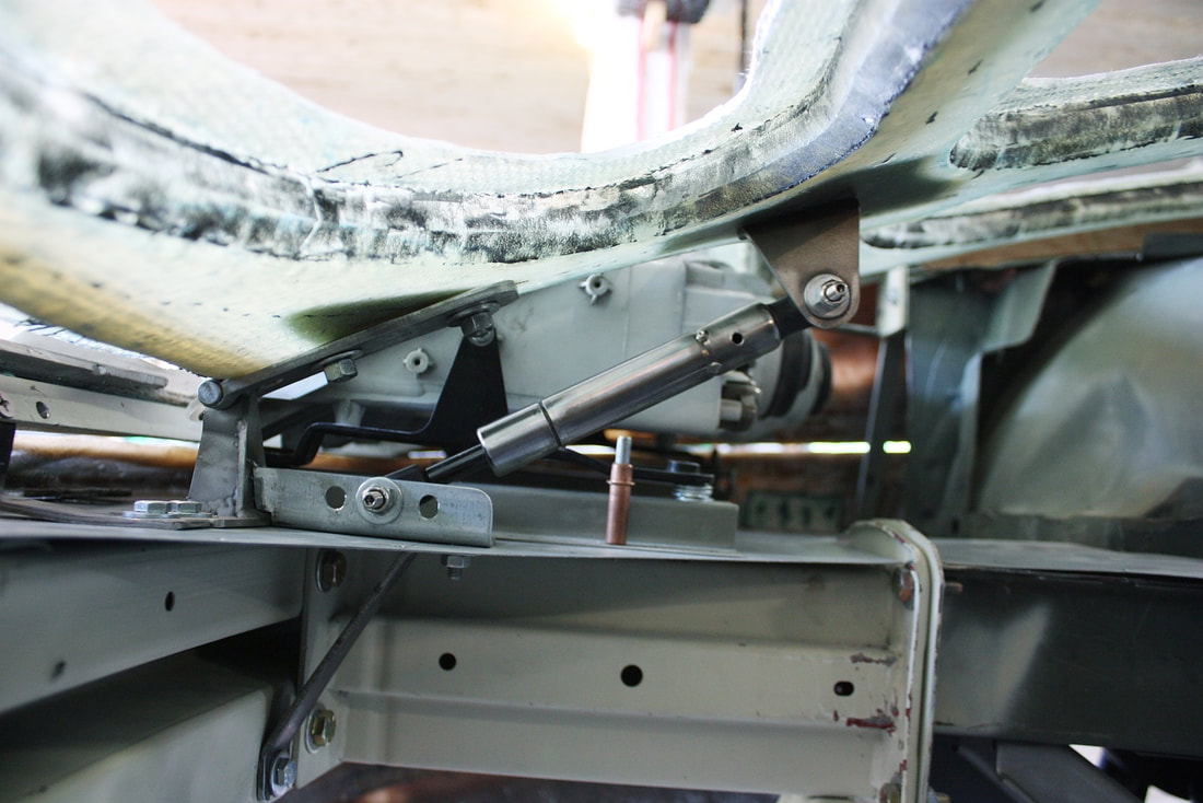
The last thing to do was run the hood through its range of travel and make sure the gas springs didn’t bind, interfere with the lights, or run out of travel themselves. Here’s the completed “open” configuration:
The last thing to do was run the hood through its range of travel and make sure the gas springs didn’t bind, interfere with the lights, or run out of travel themselves. Here’s the completed “open” configuration:
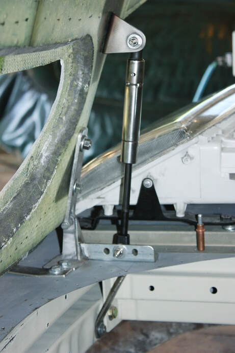
And here's the passenger side spring all folded up in the “closed” position:
And here's the passenger side spring all folded up in the “closed” position:
Once again, I was quite happy with the final layout, its compactness, and knowing that a range of spring forces to suit my final needs would be available.
Once again, I was quite happy with the final layout, its compactness, and knowing that a range of spring forces to suit my final needs would be available.

 RSS Feed
