With the fabrication of the hood hinges, latches, and gas springs sorted out, I needed to complete a bunch of smaller front-end tasks before I could move on to mounting the next major body panel. The four things remaining were to fiberglass the metal reinforcements inside the under hood webbing, complete the front fender mounting design, complete grafting the hood skin splices I’d started earlier, and bond the inner and outer hood skins together. I held off on this last one to make it easier to work on HVAC inlet and cowl designs later, but I attacked the others next.
To kick things off, I roughed up the fiberglass around the metal mounting plates inside the hood webbing, then measured and cut some heavy woven fiberglass cloth to encase them in place:
To kick things off, I roughed up the fiberglass around the metal mounting plates inside the hood webbing, then measured and cut some heavy woven fiberglass cloth to encase them in place:
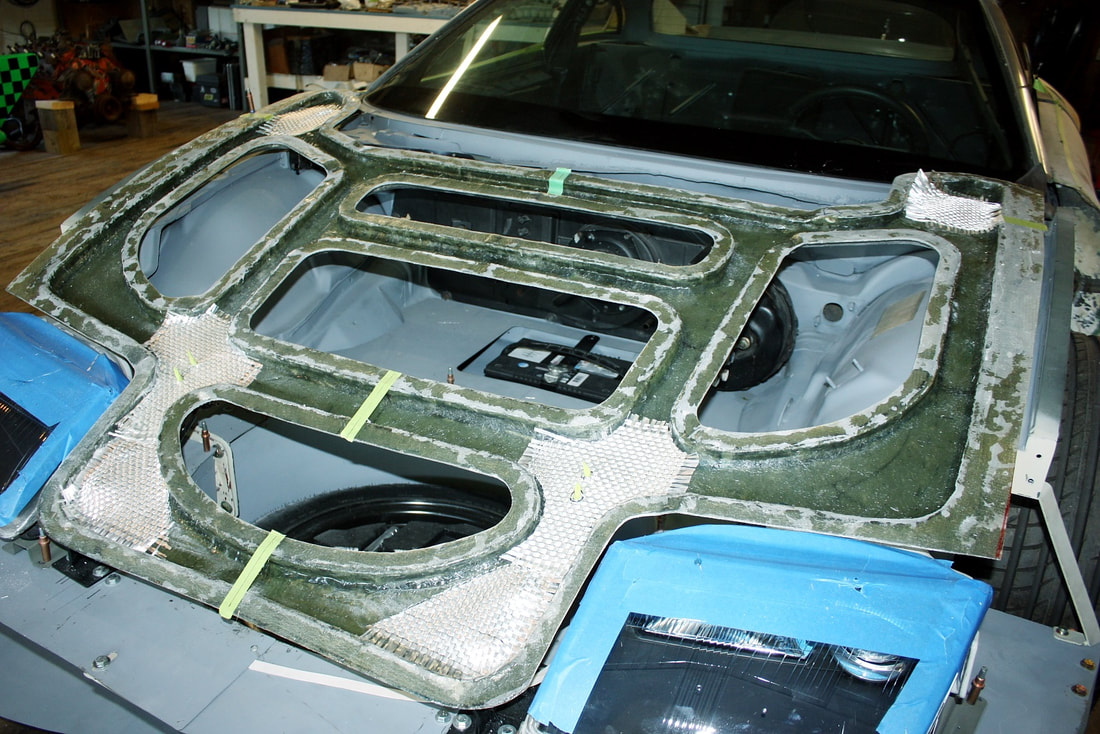
This time I was only laying up one layer so I didn’t want the resin to remain tacky between additional layers. That meant I had to mix some wax into the resin for it to cure completely:
This time I was only laying up one layer so I didn’t want the resin to remain tacky between additional layers. That meant I had to mix some wax into the resin for it to cure completely:
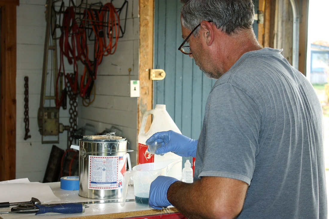
The heavier cloth took a fair bit more work to saturate with the resin, so I mixed a little less hardener in it to slow down the reaction and give me more working time. Here’s a close-up of one of the gas spring reinforcement plates already embedded in the fiberglass:
The heavier cloth took a fair bit more work to saturate with the resin, so I mixed a little less hardener in it to slow down the reaction and give me more working time. Here’s a close-up of one of the gas spring reinforcement plates already embedded in the fiberglass:

Once those were cured, I mocked up the outer hood skin onto the underhood webbing to check for the correct curvature of the hood as compared to the tops of the fenders. Things lined up really well except the very back corners of the hood skin near the windshield. They stuck up a bit, but will easily be brought into alignment once the inner and outer skins are bonded together:
Once those were cured, I mocked up the outer hood skin onto the underhood webbing to check for the correct curvature of the hood as compared to the tops of the fenders. Things lined up really well except the very back corners of the hood skin near the windshield. They stuck up a bit, but will easily be brought into alignment once the inner and outer skins are bonded together:
The same was true for the driver’s side as well. The copper Cleco fasteners sticking up in the photo are there to pull the outer skin down to the structural webbing beneath it… very little force was required:
The same was true for the driver’s side as well. The copper Cleco fasteners sticking up in the photo are there to pull the outer skin down to the structural webbing beneath it… very little force was required:
The next step was to re-level the chassis fore and aft since the addition of the battery, spare tire, and a bunch of new sheet metal up front had caused the front springs to compress. But I ran into a hiccup: I found my floor jack could no longer reach any chassis hard points:
The next step was to re-level the chassis fore and aft since the addition of the battery, spare tire, and a bunch of new sheet metal up front had caused the front springs to compress. But I ran into a hiccup: I found my floor jack could no longer reach any chassis hard points:
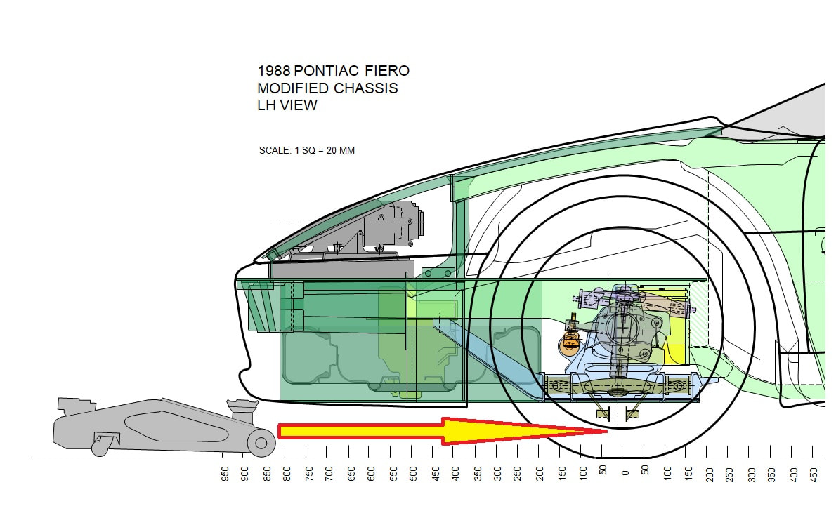
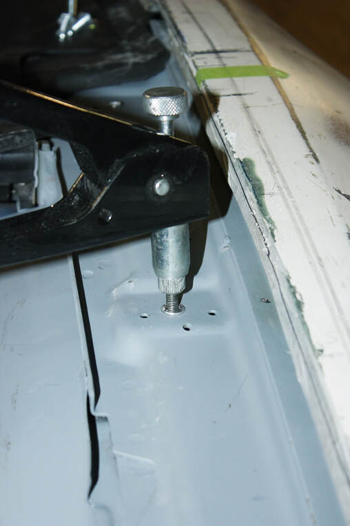
The stock Fiero jacking points up front are either under the front cross member, or under the lower control arms, but both were out of reach with the new sheet metal in place. So I got side-tracked into puzzling out a new front jacking point:
The stock Fiero jacking points up front are either under the front cross member, or under the lower control arms, but both were out of reach with the new sheet metal in place. So I got side-tracked into puzzling out a new front jacking point:
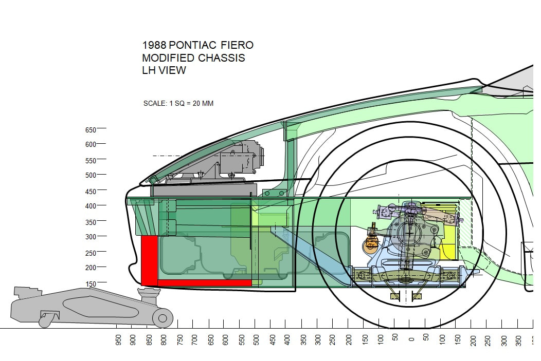
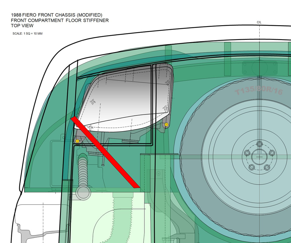
I decided to mount a 2.5” diameter metal tube that dropped down from the front rebar and would be braced fore and aft by a 1” square tube running back to the transverse spare tire brace like so:
I decided to mount a 2.5” diameter metal tube that dropped down from the front rebar and would be braced fore and aft by a 1” square tube running back to the transverse spare tire brace like so:
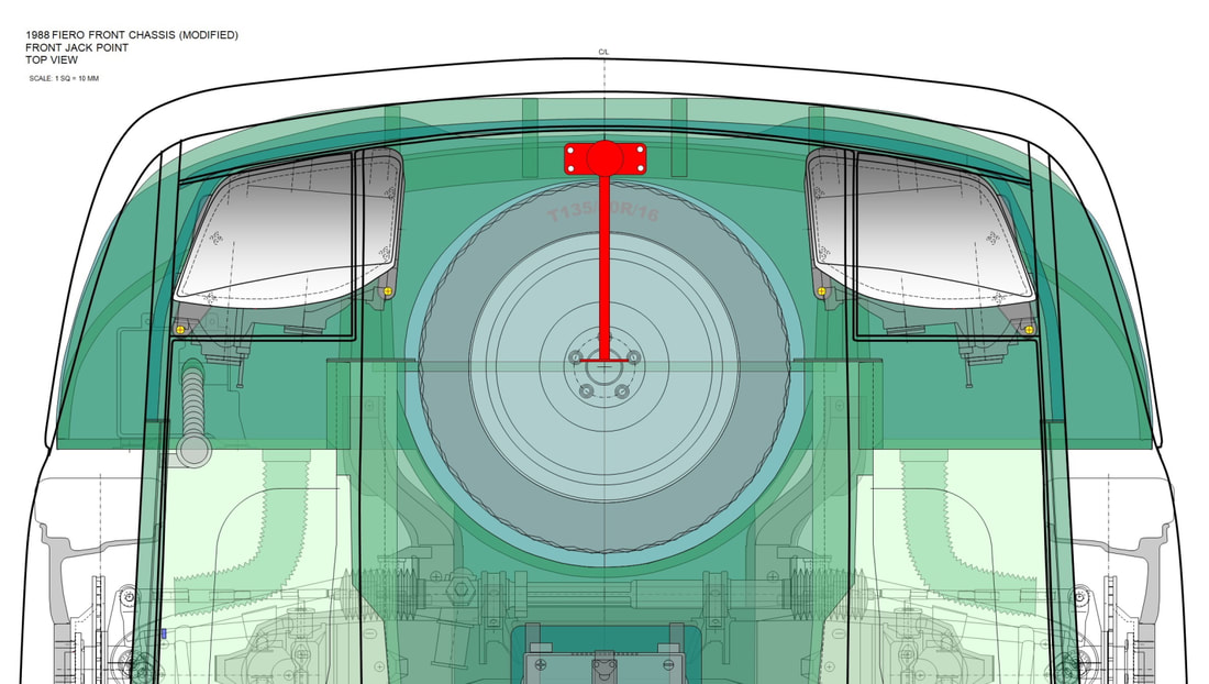
Since the loads would only ever be vertical (unless I hit something), I figured this would be plenty strong to lift the relatively light front end up for tire changes, spring height adjustments, and other front end maintenance in the future:
Since the loads would only ever be vertical (unless I hit something), I figured this would be plenty strong to lift the relatively light front end up for tire changes, spring height adjustments, and other front end maintenance in the future:
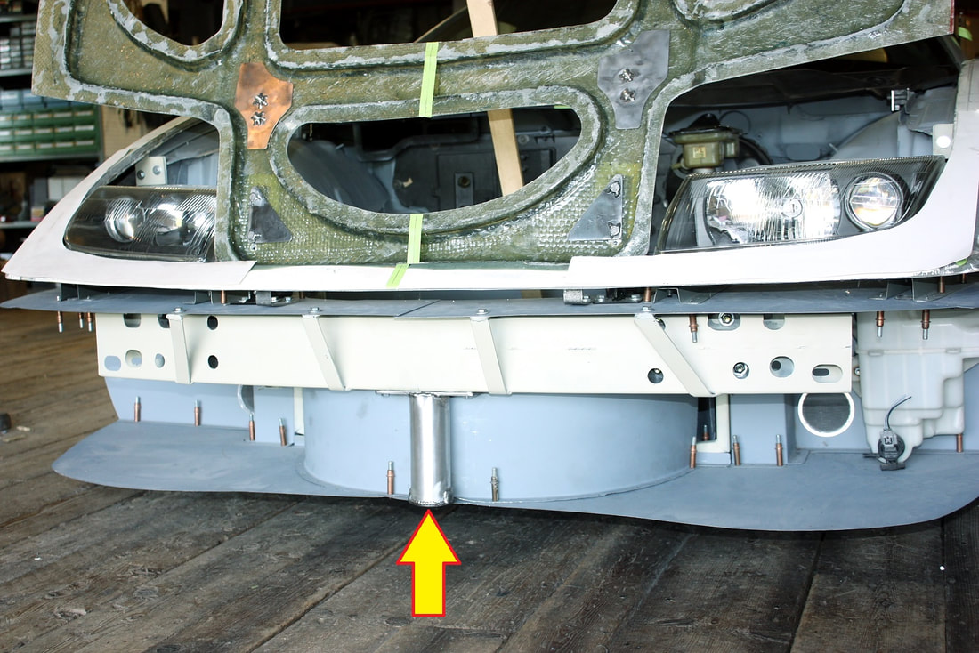
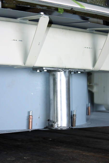
It worked like a charm with my floor jack so I was able to tweak the front springs and level the chassis. The tube will be hidden by the front grill.
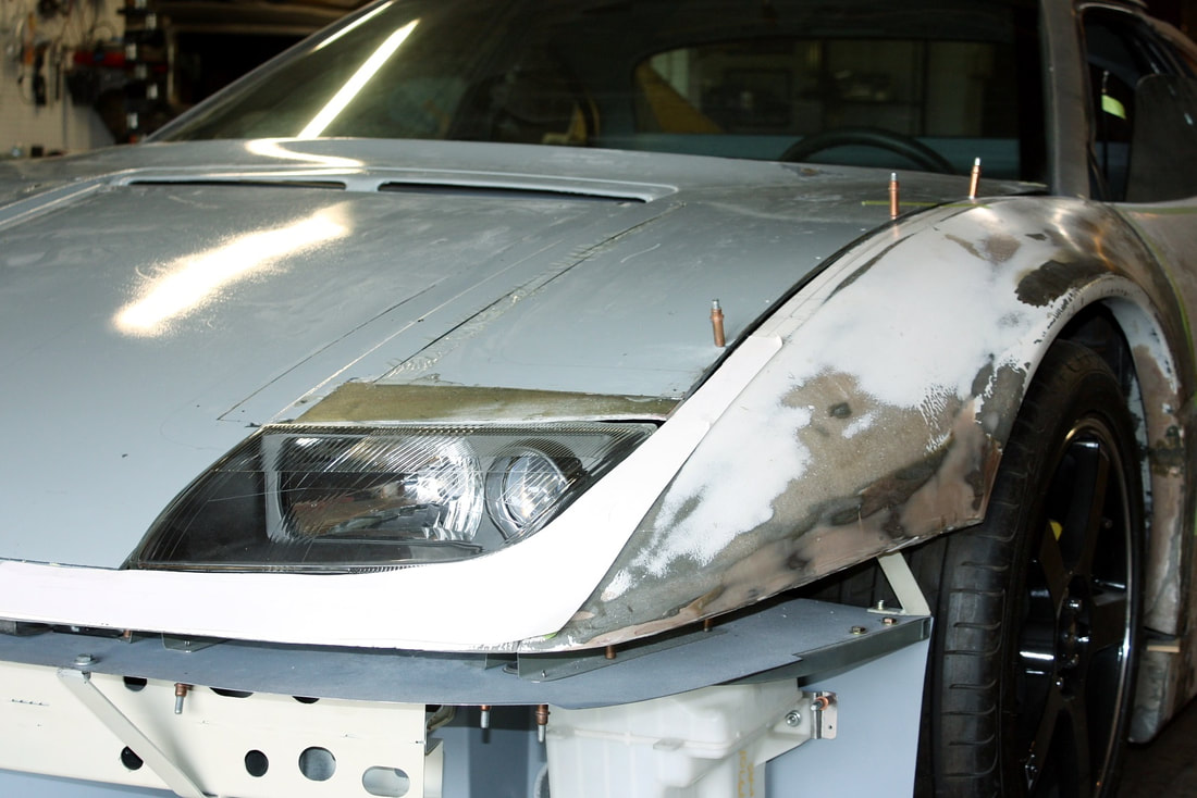
The next hiccup cropped up as I was trying to shim the height of both fenders around the headlights. I happened to lean on a headlight and the sheet metal floor it’s mounted to “oil-canned”. It popped downward a ¼” with only a bit of pressure, then popped right back up when released. Obviously I couldn’t set the fender height correctly around a headlight that couldn’t decide where it wanted to live.
To prevent oil-canning in large flat panels like the front compartment floor, metal fabricators usually use a bead roller and press in some X-shaped grooves to stiffen it. I don’t have a bead roller so my best option was to add a stiffener under the panel where it was flexing like so:
It worked like a charm with my floor jack so I was able to tweak the front springs and level the chassis. The tube will be hidden by the front grill.
The next hiccup cropped up as I was trying to shim the height of both fenders around the headlights. I happened to lean on a headlight and the sheet metal floor it’s mounted to “oil-canned”. It popped downward a ¼” with only a bit of pressure, then popped right back up when released. Obviously I couldn’t set the fender height correctly around a headlight that couldn’t decide where it wanted to live.
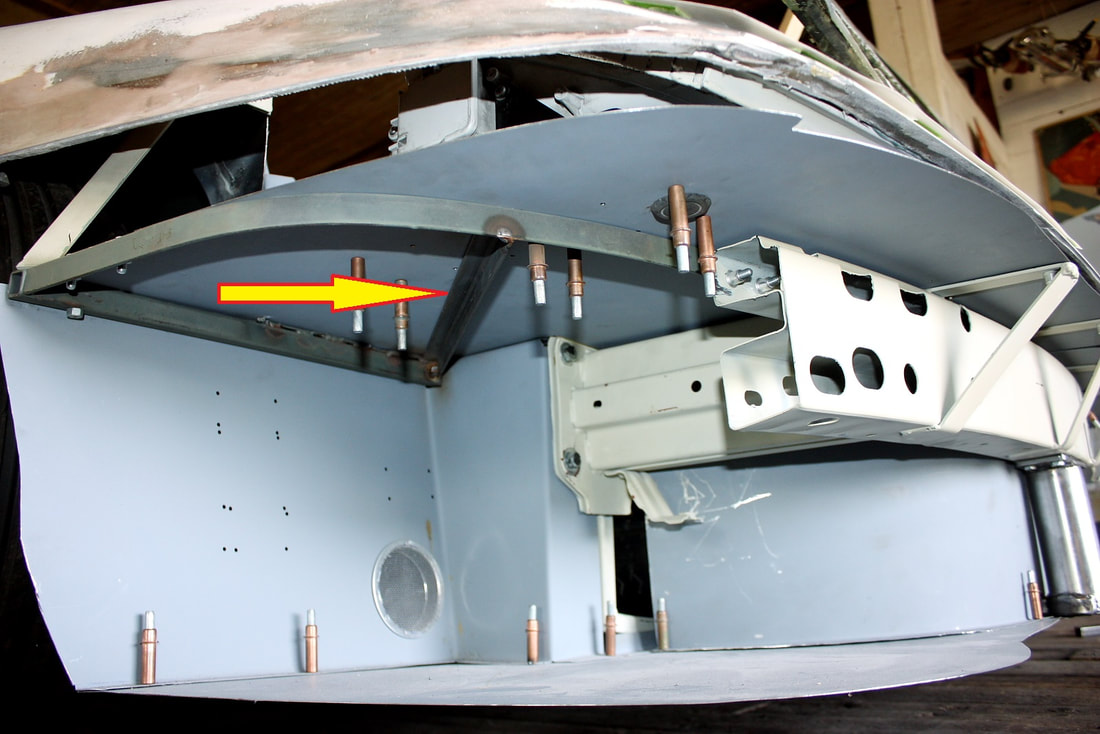
To prevent oil-canning in large flat panels like the front compartment floor, metal fabricators usually use a bead roller and press in some X-shaped grooves to stiffen it. I don’t have a bead roller so my best option was to add a stiffener under the panel where it was flexing like so:
I just cut and welded in a small ½” steel angle on the passenger and driver's sides as shown below:
I just cut and welded in a small ½” steel angle on the passenger and driver's sides as shown below:
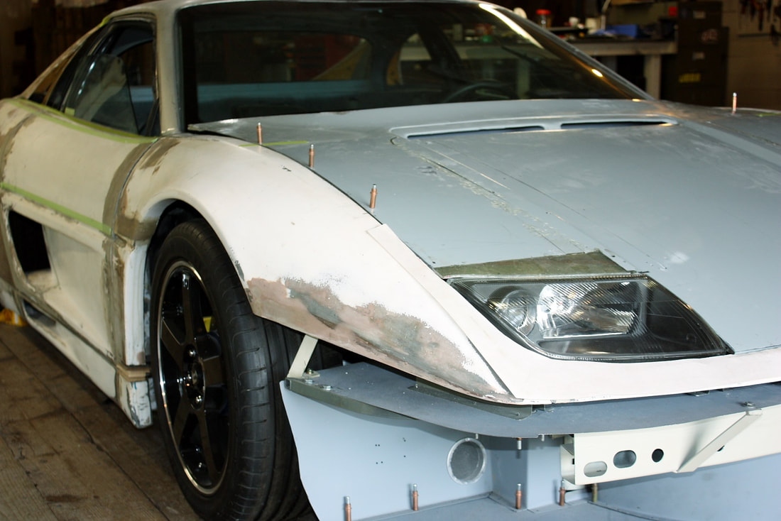
I was finally ready to complete the fender mounting job I’d started a while back. In hindsight, I should have mounted the hood first, and then moved on to the fenders since the fenders can be installed within a range of heights, but not the hood. The hood has got to clear the wipers and brake reservoir, and meet up flush with the windshield, headlights, front fascia and fenders. There’s only one position the hood can go on to meet all these criteria. With the hood position and curvature pretty much cast in stone, I could mount the fenders using the hood as the reference plane for them.
Recall that I had bonded the two front fenders to the upper front fascia making a one-piece front end, then designed mounts for the fascia portion only, and created new metal arches on top of the OEM frame rails to support the fenders from below. But until now I hadn’t figured out a way to fasten the fenders to the frame rails.
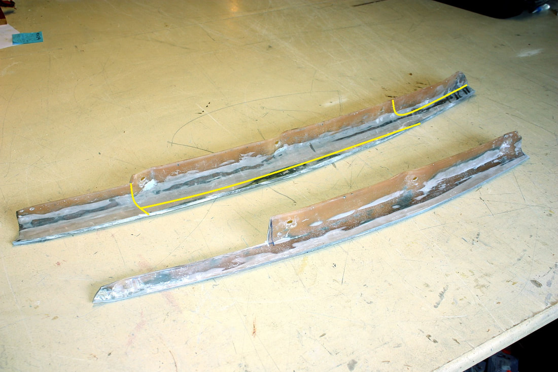
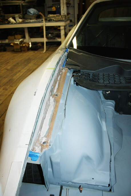
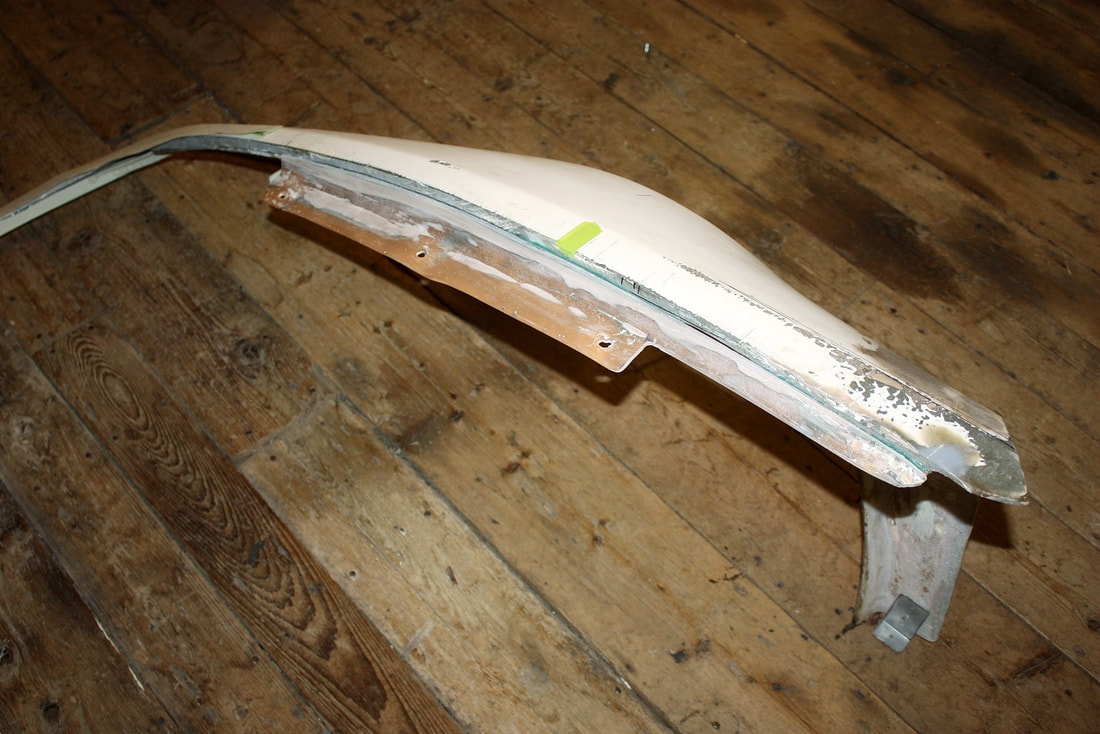
I had cut off the original IFG upper fender flanges (yellow line) since they stood far too tall:
I was finally ready to complete the fender mounting job I’d started a while back. In hindsight, I should have mounted the hood first, and then moved on to the fenders since the fenders can be installed within a range of heights, but not the hood. The hood has got to clear the wipers and brake reservoir, and meet up flush with the windshield, headlights, front fascia and fenders. There’s only one position the hood can go on to meet all these criteria. With the hood position and curvature pretty much cast in stone, I could mount the fenders using the hood as the reference plane for them.
Recall that I had bonded the two front fenders to the upper front fascia making a one-piece front end, then designed mounts for the fascia portion only, and created new metal arches on top of the OEM frame rails to support the fenders from below. But until now I hadn’t figured out a way to fasten the fenders to the frame rails.
I had cut off the original IFG upper fender flanges (yellow line) since they stood far too tall:
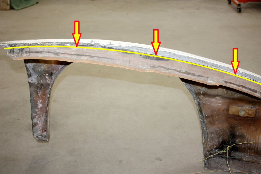
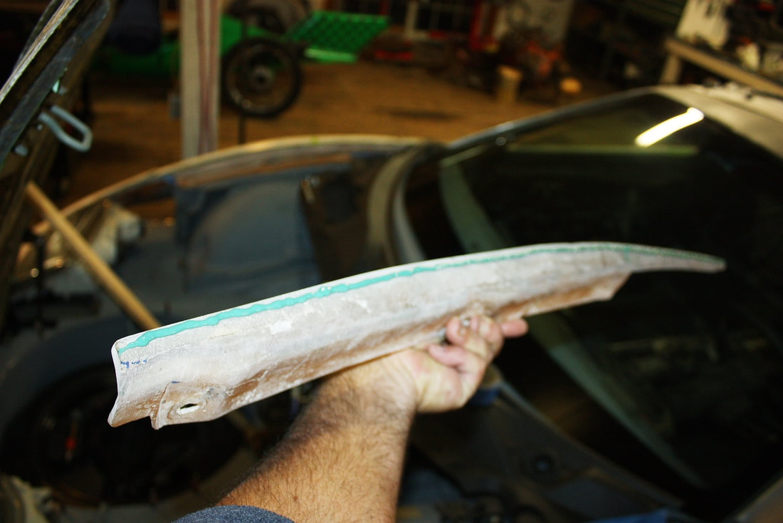
I had kept the flanges in case I’d be able to modify and reuse them… good thing too! I cut off 1.5” from their height, and then trimmed them down lengthwise as shown in this next photo. The yellow lines on the upper flange show how much more I trimmed off after reducing their height. The bottom one is all that I had left of each one once fully modified. (They’re flipped end to end so you’ll have to use your imagination a bit).
I had kept the flanges in case I’d be able to modify and reuse them… good thing too! I cut off 1.5” from their height, and then trimmed them down lengthwise as shown in this next photo. The yellow lines on the upper flange show how much more I trimmed off after reducing their height. The bottom one is all that I had left of each one once fully modified. (They’re flipped end to end so you’ll have to use your imagination a bit).
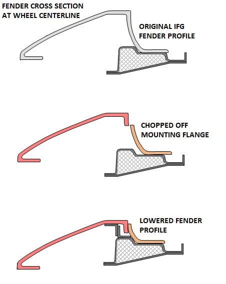
The plan was to follow the steps shown below to re-attach the chopped off, chopped down, and shortened flange:
The plan was to follow the steps shown below to re-attach the chopped off, chopped down, and shortened flange:
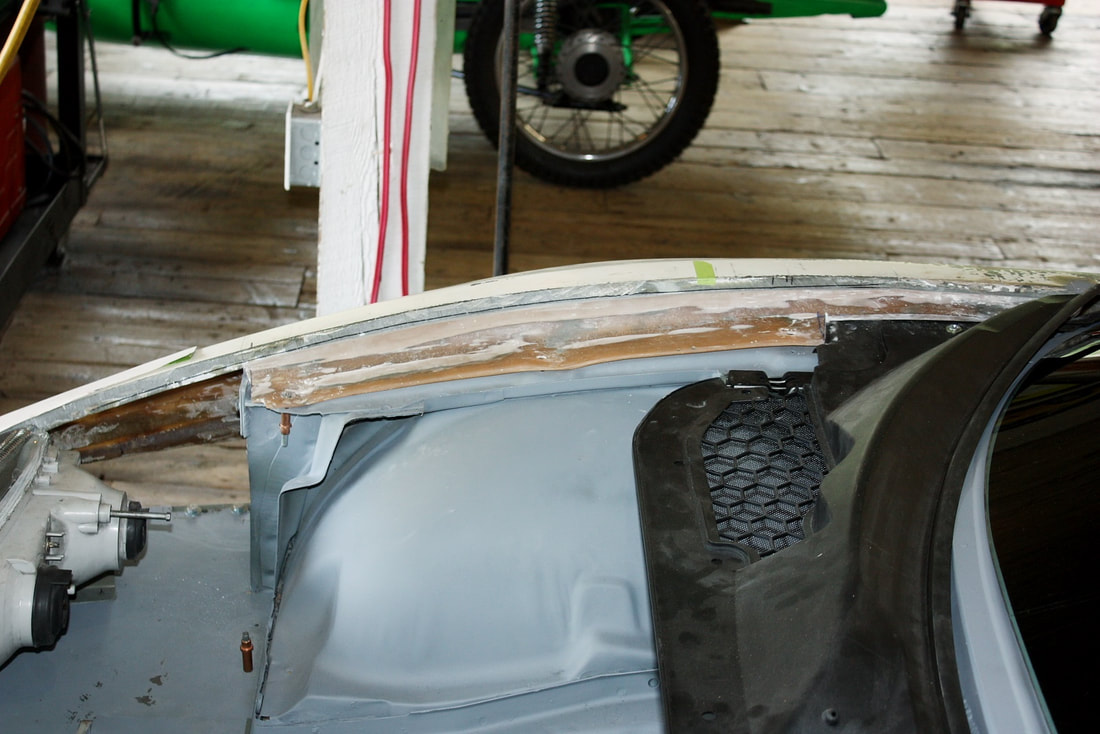
Here’s the chopped down flange mocked up on the passenger side:
Here’s the chopped down flange mocked up on the passenger side:
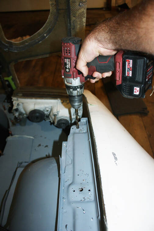
Next, since the OEM “mill & drill” mounting blocks had been removed from the upper frame rail, I re-dilled the holes in the rails to accept threaded nutserts:
Next, since the OEM “mill & drill” mounting blocks had been removed from the upper frame rail, I re-dilled the holes in the rails to accept threaded nutserts:
Then I swaged some ¼” nutserts into the top of the rails.
Then I swaged some ¼” nutserts into the top of the rails.
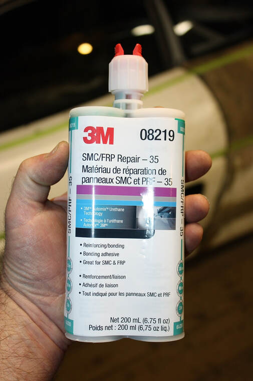
Three ¼” bolts would hold the flanges in place while I shimmed the height of the fenders against them. With everything aligned just right, I marked them, and took out the 3M adhesive made just for this sort of thing:
Three ¼” bolts would hold the flanges in place while I shimmed the height of the fenders against them. With everything aligned just right, I marked them, and took out the 3M adhesive made just for this sort of thing:
Then I took off the flanges and ran a bead of adhesive along each one:
Then I took off the flanges and ran a bead of adhesive along each one:
… and stuck them up against the fender return flange, then bolted them to the upper frame rails to hold them against the fenders while the glue hardened:
… and stuck them up against the fender return flange, then bolted them to the upper frame rails to hold them against the fenders while the glue hardened:
Once the glue had set overnight, I removed the fender assembly…
Once the glue had set overnight, I removed the fender assembly…
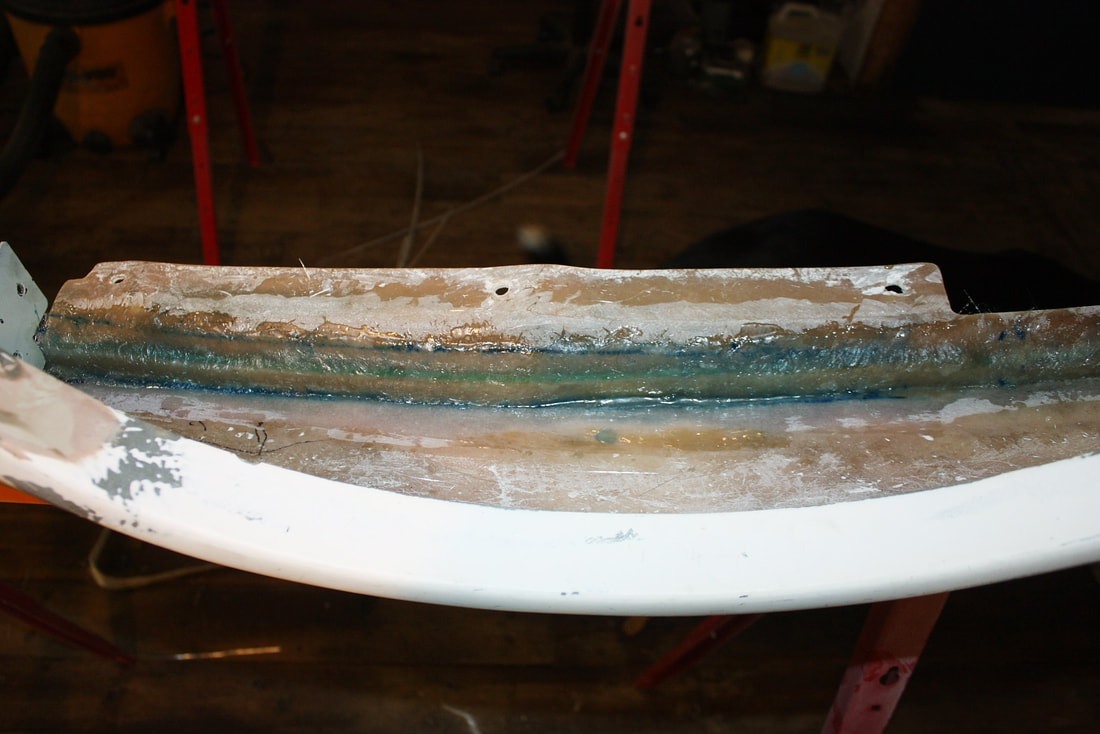
Turned it upside-down and roughed up the underside of the new flange joint to accept a layer of fiberglass for more strength:
Turned it upside-down and roughed up the underside of the new flange joint to accept a layer of fiberglass for more strength:
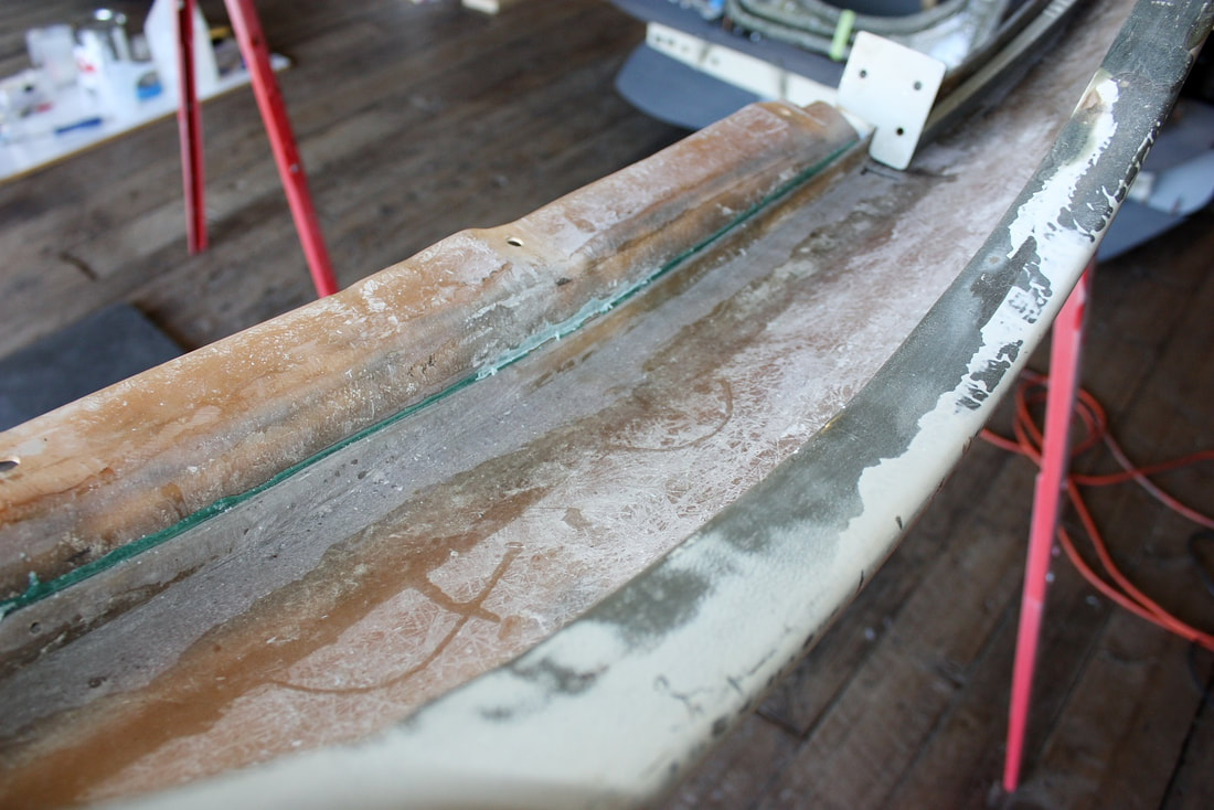
Here’s the driver’s side flange fully glassed into place on the bottom side of the fender:
Here’s the driver’s side flange fully glassed into place on the bottom side of the fender:
That’s it for mounting the front clip, at least for now. I still have to re-build the bottom corners of the fenders where they attach to the rockers, but since that's another multi-panel alignment area I’m going to wait until the doors and rockers get their make-overs before tackling them.
That’s it for mounting the front clip, at least for now. I still have to re-build the bottom corners of the fenders where they attach to the rockers, but since that's another multi-panel alignment area I’m going to wait until the doors and rockers get their make-overs before tackling them.
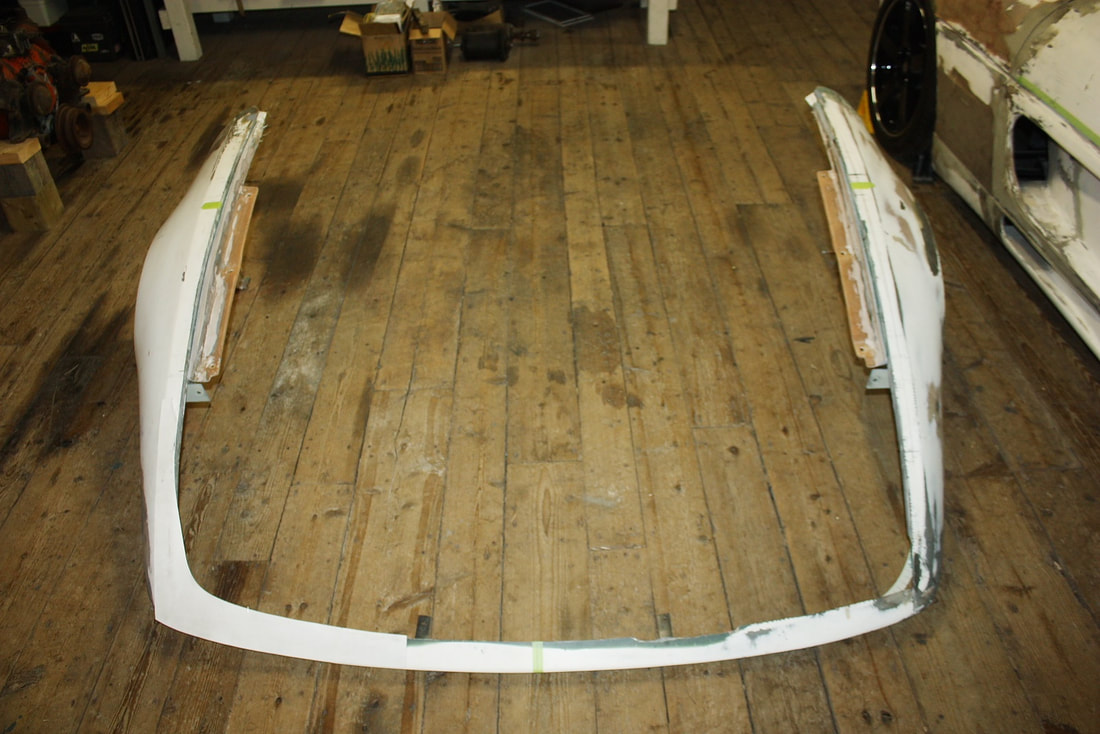
Also, recall from Post 120 that I’m still only in the “Mounting” phase right now. The goal is to create mounting points so I'll have repeatability in panel positioning before I move to the next phase which is "Patchwork". That's when I’ll re-form the curved area around the headlights with new fiberglass (right now it’s just cardboard) and re-shape the wheel arches too.
Also, recall from Post 120 that I’m still only in the “Mounting” phase right now. The goal is to create mounting points so I'll have repeatability in panel positioning before I move to the next phase which is "Patchwork". That's when I’ll re-form the curved area around the headlights with new fiberglass (right now it’s just cardboard) and re-shape the wheel arches too.

 RSS Feed
