The “flying buttresses”, C-pillars, or sail panels (whatever you choose to call them) were next in line for some attention. Here’s a quick review of what was left of the IFG sail panels once I’d chopped out the unusable parts:
The “flying buttresses”, C-pillars, or sail panels (whatever you choose to call them) were next in line for some attention. Here’s a quick review of what was left of the IFG sail panels once I’d chopped out the unusable parts:
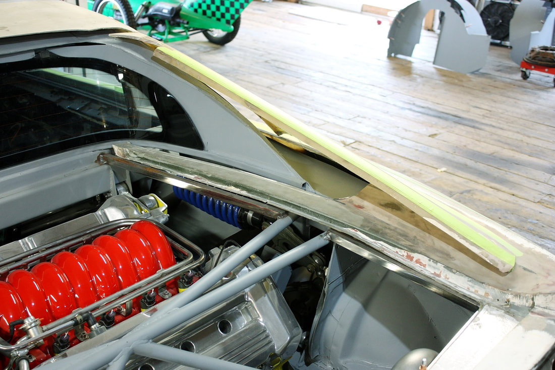
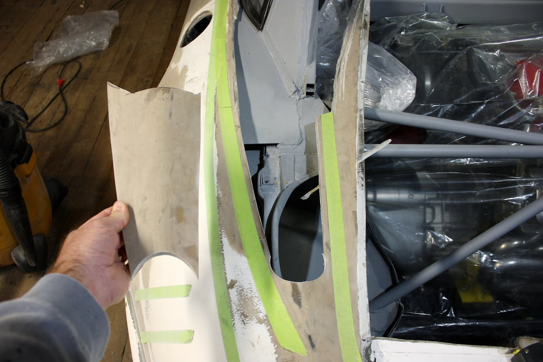
I obviously needed to recreate the inboard walls of the sail panels, so the first step was to determine where they should land on the quarter panel. I drew some nicely arched lines running back from the rear corners of the MR2 window to the ducktail spoiler at the back. Then laid out some masking tape as a guide and decided to remove as much material as I dared between the inner and outer guides:
I obviously needed to recreate the inboard walls of the sail panels, so the first step was to determine where they should land on the quarter panel. I drew some nicely arched lines running back from the rear corners of the MR2 window to the ducktail spoiler at the back. Then laid out some masking tape as a guide and decided to remove as much material as I dared between the inner and outer guides:
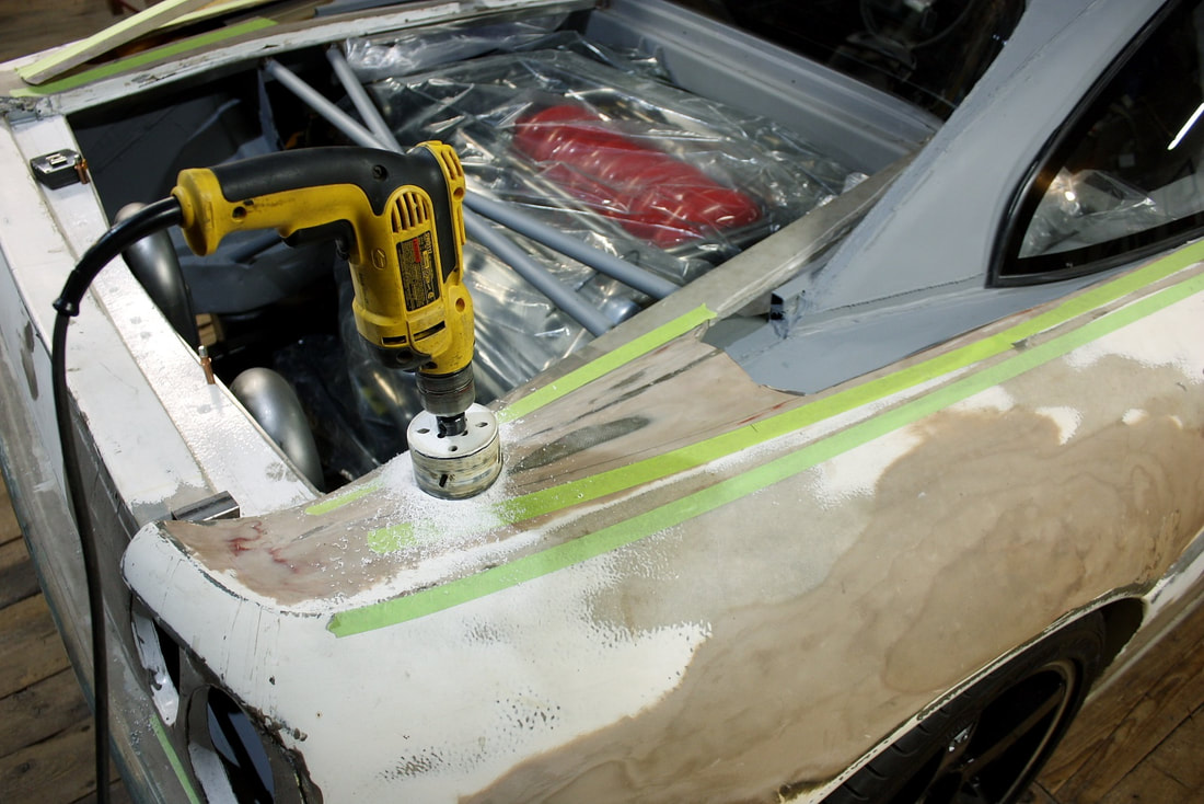
I had two reasons for doing this: a. the hole for the decklid was too wide, so separating the outer fender from the decklid surround would allow me to lever the surround inboard and close the gap and; b. I intend on using the air scoop behind the quarter window to funnel cold air to the engine air filter on one side, and cooling air for the PCM on the other. That meant I needed to open an air path from the scoop to the former trunk compartment under the sail panel:
I had two reasons for doing this: a. the hole for the decklid was too wide, so separating the outer fender from the decklid surround would allow me to lever the surround inboard and close the gap and; b. I intend on using the air scoop behind the quarter window to funnel cold air to the engine air filter on one side, and cooling air for the PCM on the other. That meant I needed to open an air path from the scoop to the former trunk compartment under the sail panel:
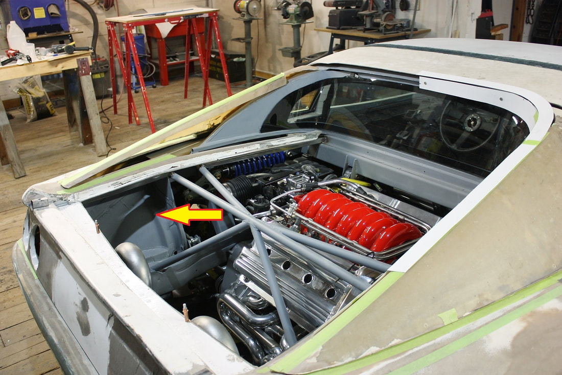
Eventually, I’ll form a large fibreglass funnel that fits inside the sail panel and redirects the air from the quarter window scoop into the trunk, like so:
Eventually, I’ll form a large fibreglass funnel that fits inside the sail panel and redirects the air from the quarter window scoop into the trunk, like so:
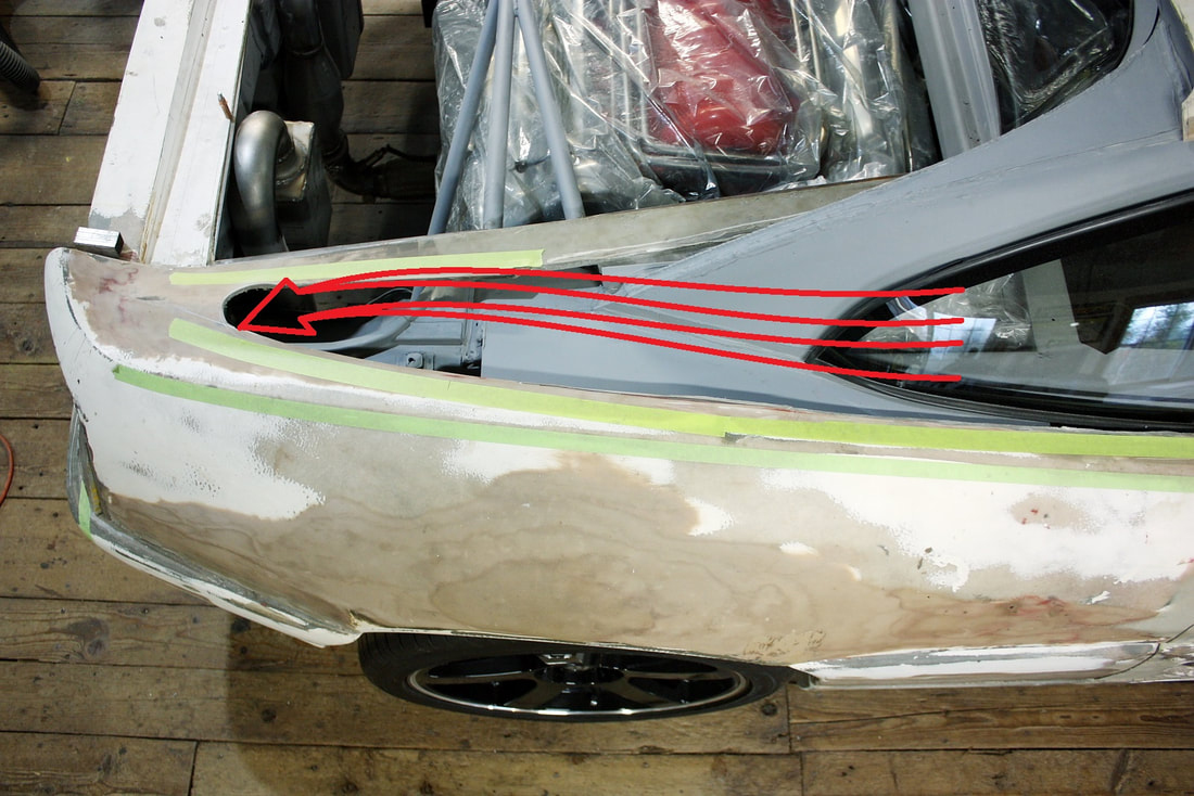
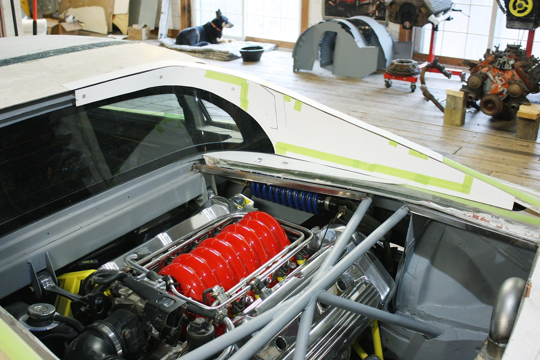
On the passenger side, the air will be forced into a custom fibreglass box tucked in the space behind the taillights and will house the PCM. Air will exit through the rear of the box and out the F1 style taillight grill. On the driver’s side, the funnel will lead into a custom air filter box and be plumbed to the engine like this:
On the passenger side, the air will be forced into a custom fibreglass box tucked in the space behind the taillights and will house the PCM. Air will exit through the rear of the box and out the F1 style taillight grill. On the driver’s side, the funnel will lead into a custom air filter box and be plumbed to the engine like this:
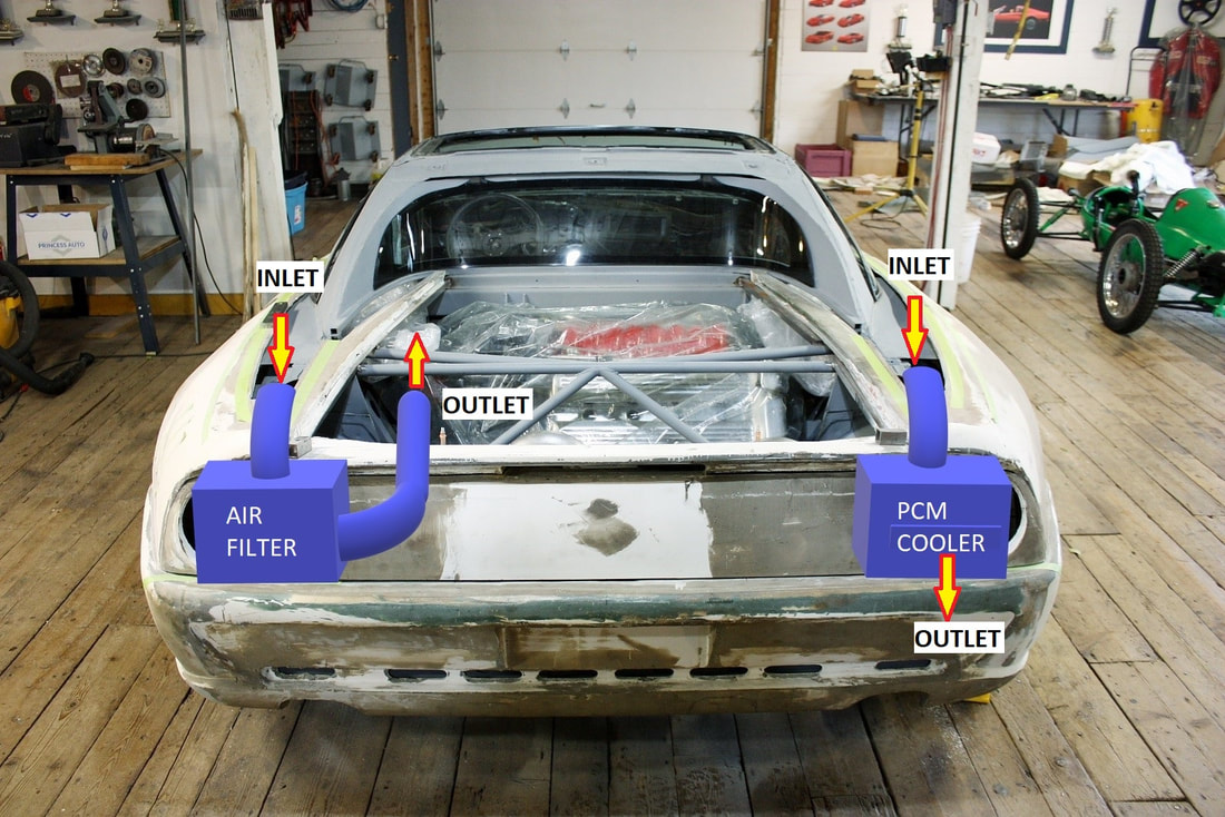
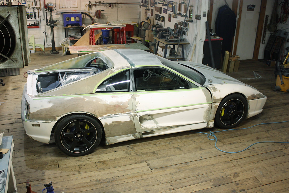
Here’s a better view of the space these boxes will take up:
Here’s a better view of the space these boxes will take up:
But I’m getting ahead of myself. This post is about closing off the sail panels, so with that detail roughed in, I re-focused my efforts on developing a mold.
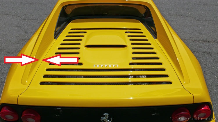
After researching what the real F355 inboard sail panel walls looked like, I realized there would have to be a concession made to authenticity on mine. The Ferrari’s inner sail panel walls follow within a half inch or so of the decklid opening:
But I’m getting ahead of myself. This post is about closing off the sail panels, so with that detail roughed in, I re-focused my efforts on developing a mold.
After researching what the real F355 inboard sail panel walls looked like, I realized there would have to be a concession made to authenticity on mine. The Ferrari’s inner sail panel walls follow within a half inch or so of the decklid opening:
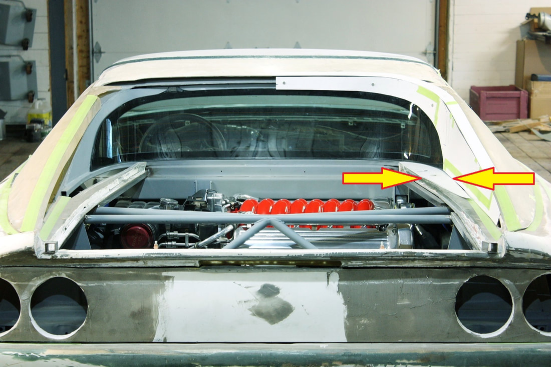
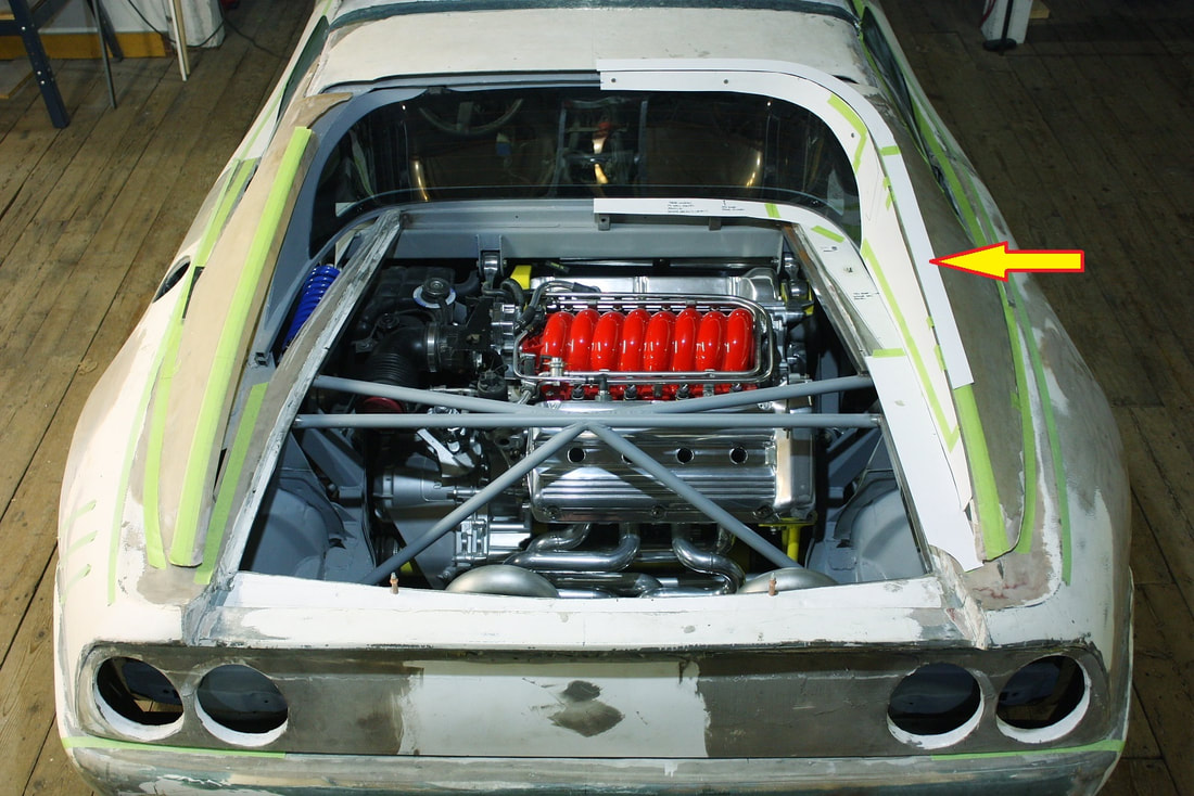
The problem with my car is that the MR2 rear window is about 2” wider per side than the decklid opening. Since the sails must be as wide as the window, I needed to accept a 2” wide perimeter on either side of the decklid:
The problem with my car is that the MR2 rear window is about 2” wider per side than the decklid opening. Since the sails must be as wide as the window, I needed to accept a 2” wide perimeter on either side of the decklid:
I did briefly consider widening the decklid, but it would’ve left it horribly misshaped since it would’ve had to be widened 4” in the front, and none at all in the back given its tapered shape. For me, the lesser of two evils was to have the 2” surround rather than have a square decklid. Some of excess surround will be taken up by the generous radius at the base of the sail panels, but not all of it.
Moving on, I made a set of cardboard templates replicating the sail panel inboard wall, extending it at the top to curve around the rear-facing edge of the roof:
I also traced a template for the flat, top edge of the sail panel. The authentic F355 has a flat 1.5” wide surface that runs along the top of the sail panels and across the roof. It also has fairly distinct corners on either side, whereas this same surface on the IFG panel was rounded, and the edges ill-defined. I decided by incorporating a new “track” as an integral part of the sail panel, it would kill two birds with one stone. It would do double-duty acting as a return flange helping retain the curvature of the wall once pulled from the mold, and provide a handy bonding flange to the outer walls. (Disregard the lower templates surrounding the engine bay).
I also traced a template for the flat, top edge of the sail panel. The authentic F355 has a flat 1.5” wide surface that runs along the top of the sail panels and across the roof. It also has fairly distinct corners on either side, whereas this same surface on the IFG panel was rounded, and the edges ill-defined. I decided by incorporating a new “track” as an integral part of the sail panel, it would kill two birds with one stone. It would do double-duty acting as a return flange helping retain the curvature of the wall once pulled from the mold, and provide a handy bonding flange to the outer walls. (Disregard the lower templates surrounding the engine bay).
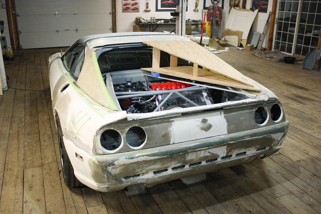
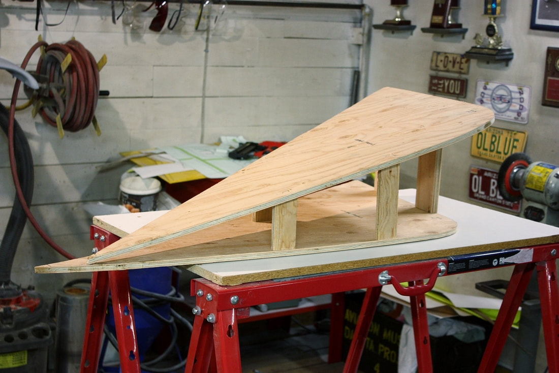
With the templates finalized, I began fabricating a cheap, two-use jig to mold the new fibreglass panels. I cut ½” plywood into upper and lower profiles of the roof-to-sail-panel intersection, then joined them together with a couple vertical stilts to capture their offsets from each other like so:
With the templates finalized, I began fabricating a cheap, two-use jig to mold the new fibreglass panels. I cut ½” plywood into upper and lower profiles of the roof-to-sail-panel intersection, then joined them together with a couple vertical stilts to capture their offsets from each other like so:
Once it was sturdy enough to transport to my workbench, I took it off and sanded the appropriate bevels along the outside edges with a belt sander…
Once it was sturdy enough to transport to my workbench, I took it off and sanded the appropriate bevels along the outside edges with a belt sander…
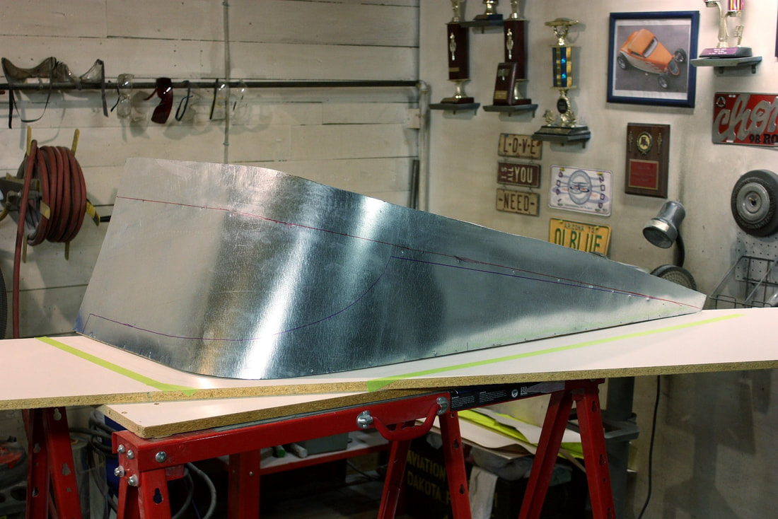
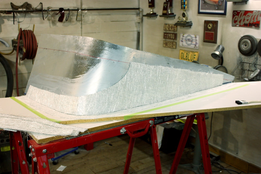
…then made, cut, and installed a sheet metal skin to mimic the shape of the inboard wall:
…then made, cut, and installed a sheet metal skin to mimic the shape of the inboard wall:
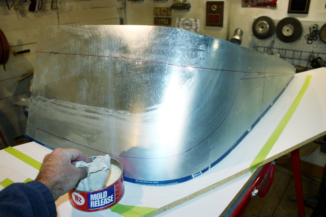
I then waxed the sheet metal and the melamine base to make sure the polyester resin wouldn’t stick to my makeshift mold:
I then waxed the sheet metal and the melamine base to make sure the polyester resin wouldn’t stick to my makeshift mold:
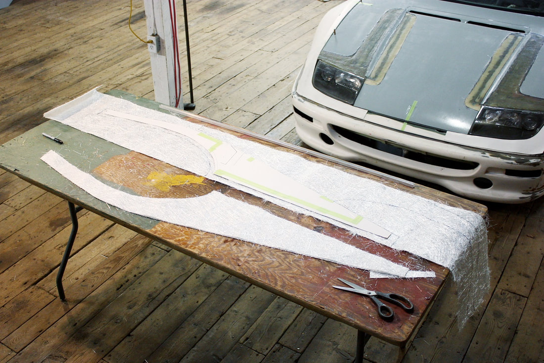
By now, the rest of this is old hat for anyone who’s been following along. Using my cardboard templates, I cut four wall patterns and four top tracks of 1.5 oz fibreglass mat per side leaving generous margins:
By now, the rest of this is old hat for anyone who’s been following along. Using my cardboard templates, I cut four wall patterns and four top tracks of 1.5 oz fibreglass mat per side leaving generous margins:
I dry-fitted the mat to the mold to be sure both pieces would fit tightly together along the base (which in reality is the top outside corner since the mold is upside down):
I dry-fitted the mat to the mold to be sure both pieces would fit tightly together along the base (which in reality is the top outside corner since the mold is upside down):
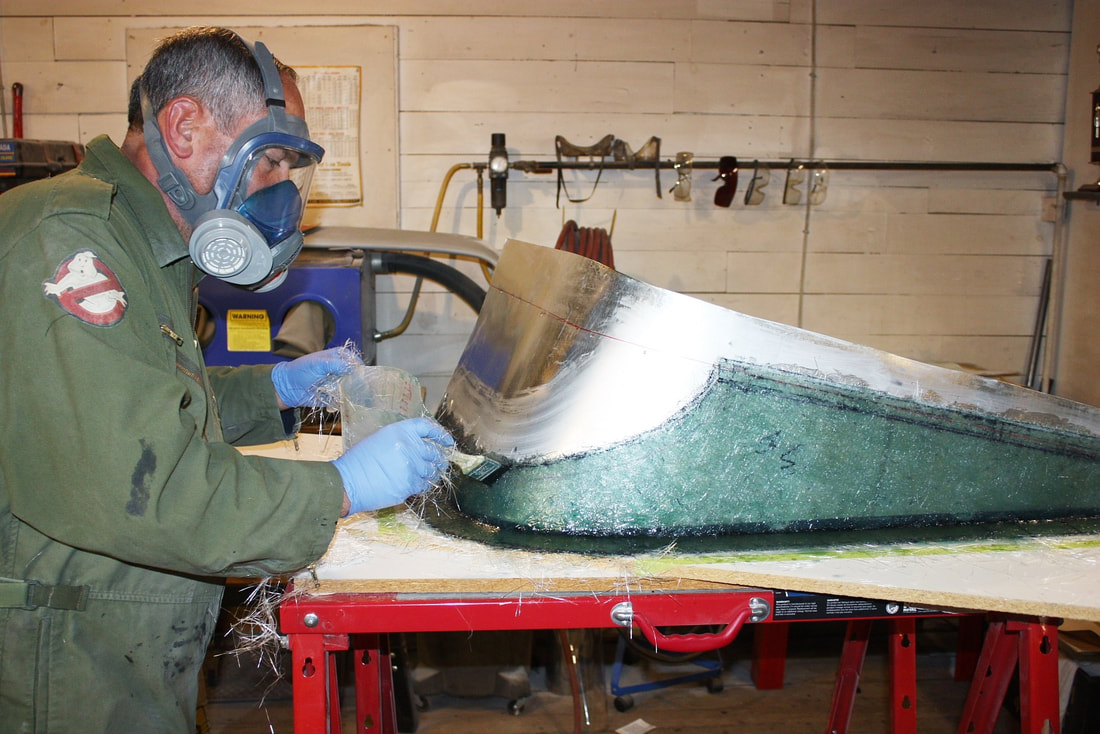
Then I got busy mixing up 2 cups of resin at a time. With my shop temperature hovering around 20 degrees C, it only took 20 mins to start hardening. Two cups was all I could manage to use in that amount of time. In all, I needed five cups to saturate all four layers of one panel:
Then I got busy mixing up 2 cups of resin at a time. With my shop temperature hovering around 20 degrees C, it only took 20 mins to start hardening. Two cups was all I could manage to use in that amount of time. In all, I needed five cups to saturate all four layers of one panel:
Once the first panel had set up and been extracted from the mold, I tore the jig down, flipped the pieces around, and remade a mirror image of the jig to make the opposite side panel. Here’s the first one freshly popped:
Once the first panel had set up and been extracted from the mold, I tore the jig down, flipped the pieces around, and remade a mirror image of the jig to make the opposite side panel. Here’s the first one freshly popped:
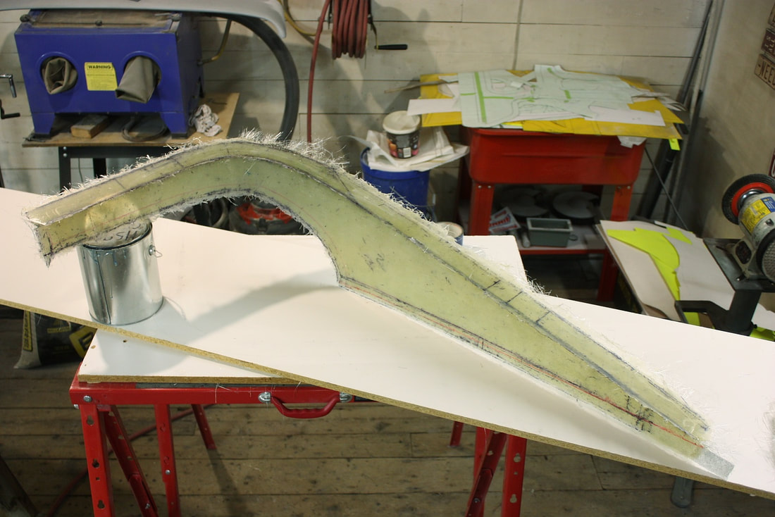
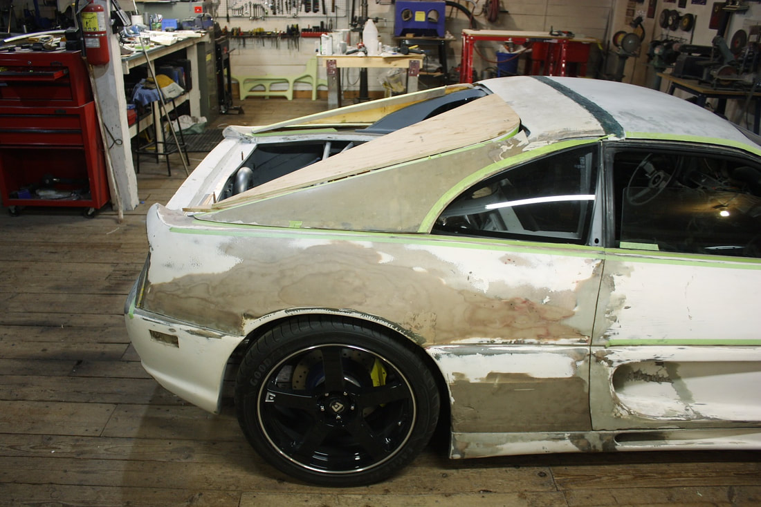
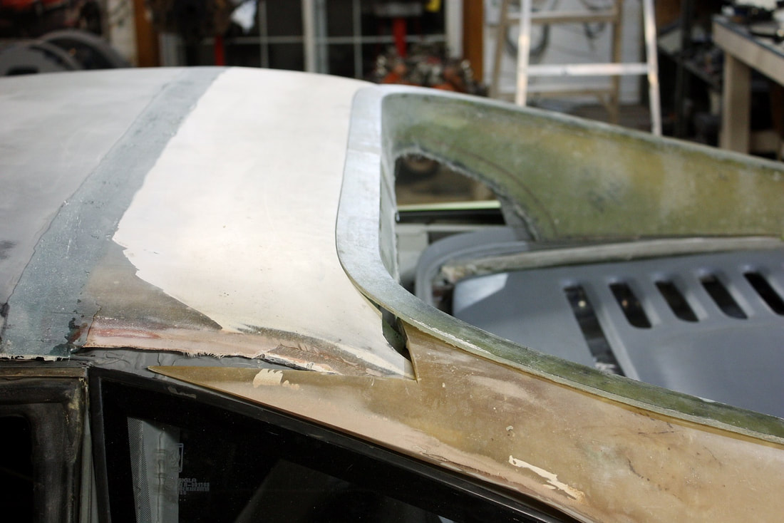
With both sides made, I trimmed the excess off and mocked them up on the car. They fit really well but will need a bit of filler to flatten out some minor waviness that was in the sheet metal mold. You can see the high and low spots on the driver’s side panel after I gave it a light sanding… nothing unexpected, or worrisome:
With both sides made, I trimmed the excess off and mocked them up on the car. They fit really well but will need a bit of filler to flatten out some minor waviness that was in the sheet metal mold. You can see the high and low spots on the driver’s side panel after I gave it a light sanding… nothing unexpected, or worrisome:
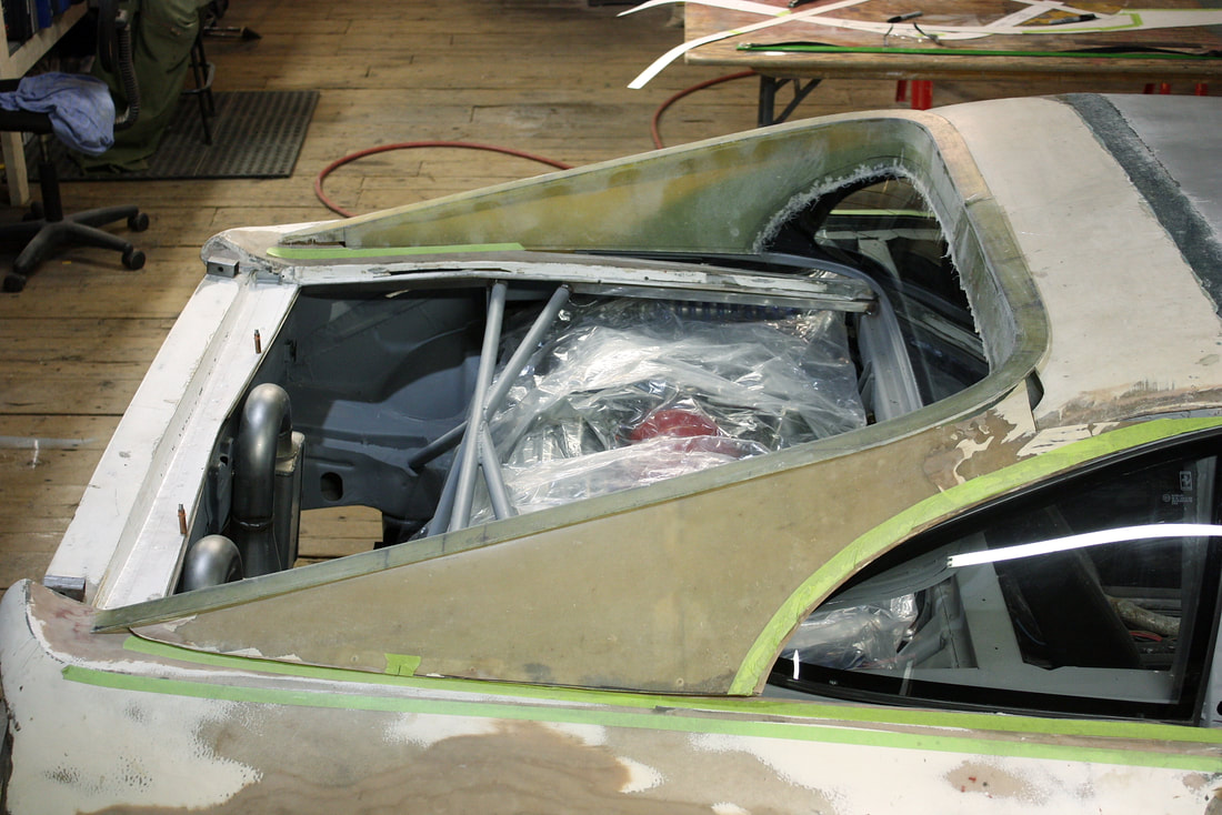
With the panels just sitting in place, I could tell that the molding process was a success. The two parts lined up nearly perfectly:
With the panels just sitting in place, I could tell that the molding process was a success. The two parts lined up nearly perfectly:
I didn’t trim the excess 1" flashing around the rear window opening because I wasn’t 100% sure how high the window would sit when properly installed. On a whim, I ordered the OEM lower trim molding for the MR2 glass, which I believe the window sits on top of, but it hadn’t arrived at the time of this post. If I end up using it, it will likely raise the rear window by an amount unknown to me at this time, so I decided to wait for it to arrive before trimming the window opening. Measure twice, cut once!:
I didn’t trim the excess 1" flashing around the rear window opening because I wasn’t 100% sure how high the window would sit when properly installed. On a whim, I ordered the OEM lower trim molding for the MR2 glass, which I believe the window sits on top of, but it hadn’t arrived at the time of this post. If I end up using it, it will likely raise the rear window by an amount unknown to me at this time, so I decided to wait for it to arrive before trimming the window opening. Measure twice, cut once!:
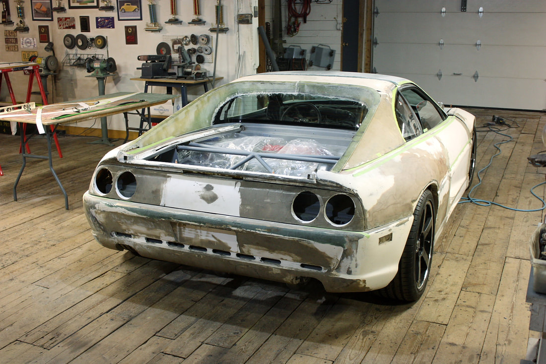
And finally stepping back to get an overall look:
And finally stepping back to get an overall look:

 RSS Feed
