| In my last post, I fabbed up some new inboard walls for the sail panels and mocked them up onto the old IFG outer walls. Luckily I was thinking ahead when I cut up the outer panels by leaving a flange along the top of the outer walls as a bonding surface for the new inners. To bond the new and old panels together, I decided to try a less expensive adhesive by Norton. It’s an epoxy-based glue for bonding pretty much anything to anything else, for about $55, or half the cost of the 3M product I used before: | 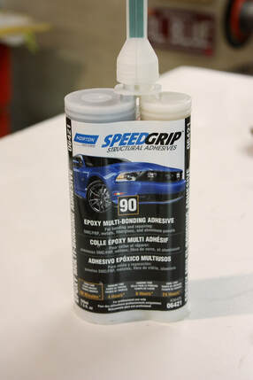 |
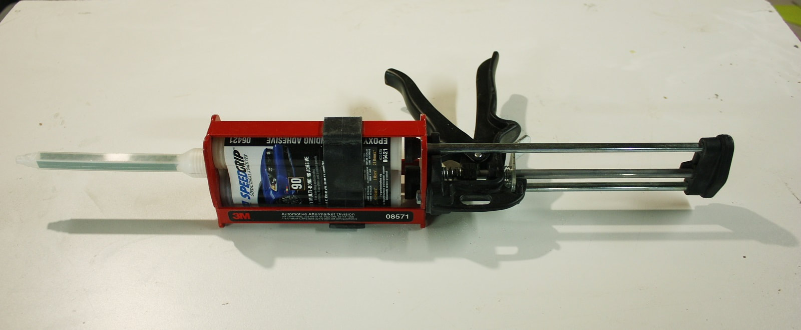
Like the 3M product, it also uses a special twin-barrel caulking gun ($200) and special one-time-use mixing nozzles. It’s an indispensable tool for working with fibreglass panels:
Like the 3M product, it also uses a special twin-barrel caulking gun ($200) and special one-time-use mixing nozzles. It’s an indispensable tool for working with fibreglass panels:
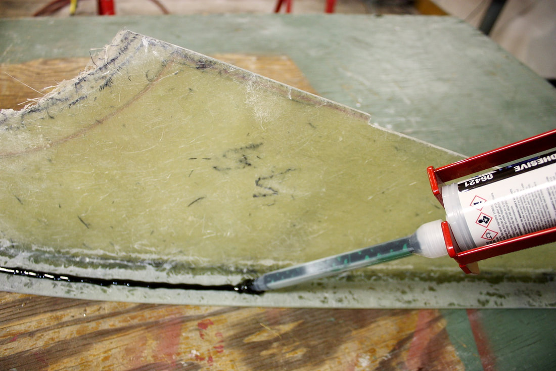
The instructions call for placing a bead on each surface, spreading it out uniformly, then adding a second bead on one part before sticking them together. Here, I’m applying the first bead to the underside of a new inboard sail panel after having roughed up the surface with 80 grit paper:
The instructions call for placing a bead on each surface, spreading it out uniformly, then adding a second bead on one part before sticking them together. Here, I’m applying the first bead to the underside of a new inboard sail panel after having roughed up the surface with 80 grit paper:
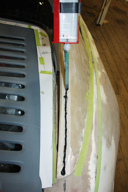
Then, to make sure the two panels would be glued at the proper angle and location relative to each other, I mocked up the outer panel on the chassis, and added a bead of adhesive to the mating flange:
Then, to make sure the two panels would be glued at the proper angle and location relative to each other, I mocked up the outer panel on the chassis, and added a bead of adhesive to the mating flange:
I used a little paint spatula to spread out the adhesive on both panels…
I used a little paint spatula to spread out the adhesive on both panels…
… then added the last bead and stuck the two panels together:
… then added the last bead and stuck the two panels together:
The pieces fit so well together that I only needed a small weight on one panel to keep them oriented correctly. Here are both sails mocked up and curing:
The pieces fit so well together that I only needed a small weight on one panel to keep them oriented correctly. Here are both sails mocked up and curing:
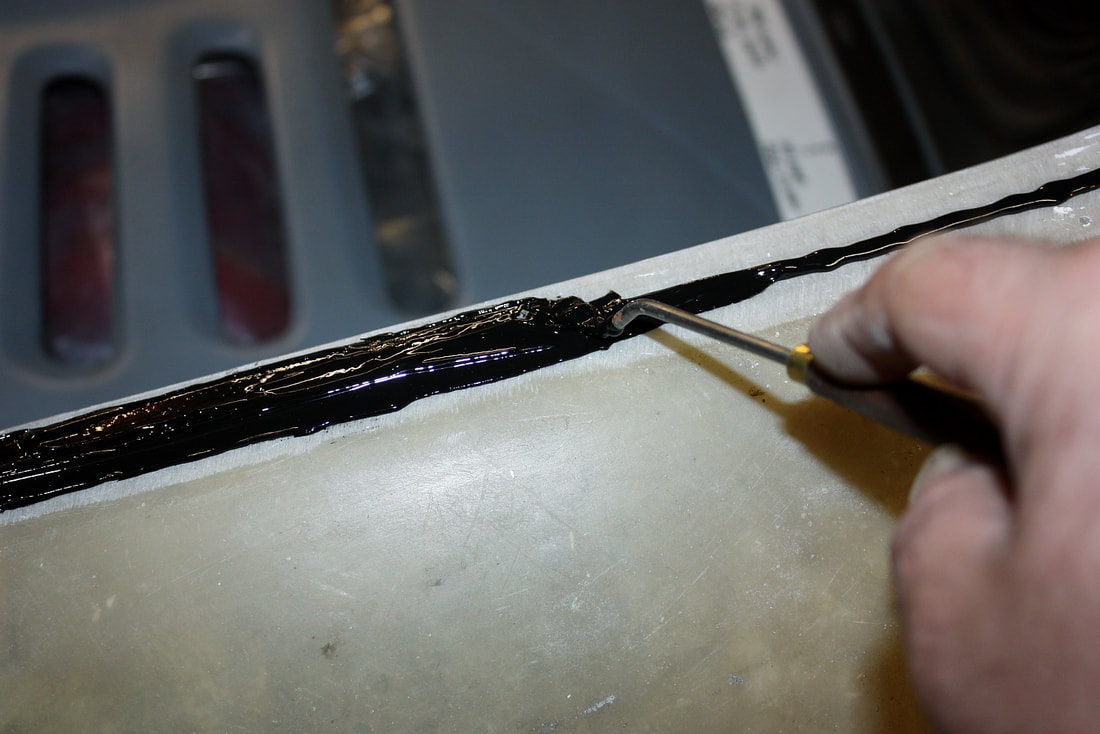
Full strength is achieved after 24 hours, so the next day I was able to remove them from the chassis, and trim the excess adhesive off the joints:
Full strength is achieved after 24 hours, so the next day I was able to remove them from the chassis, and trim the excess adhesive off the joints:
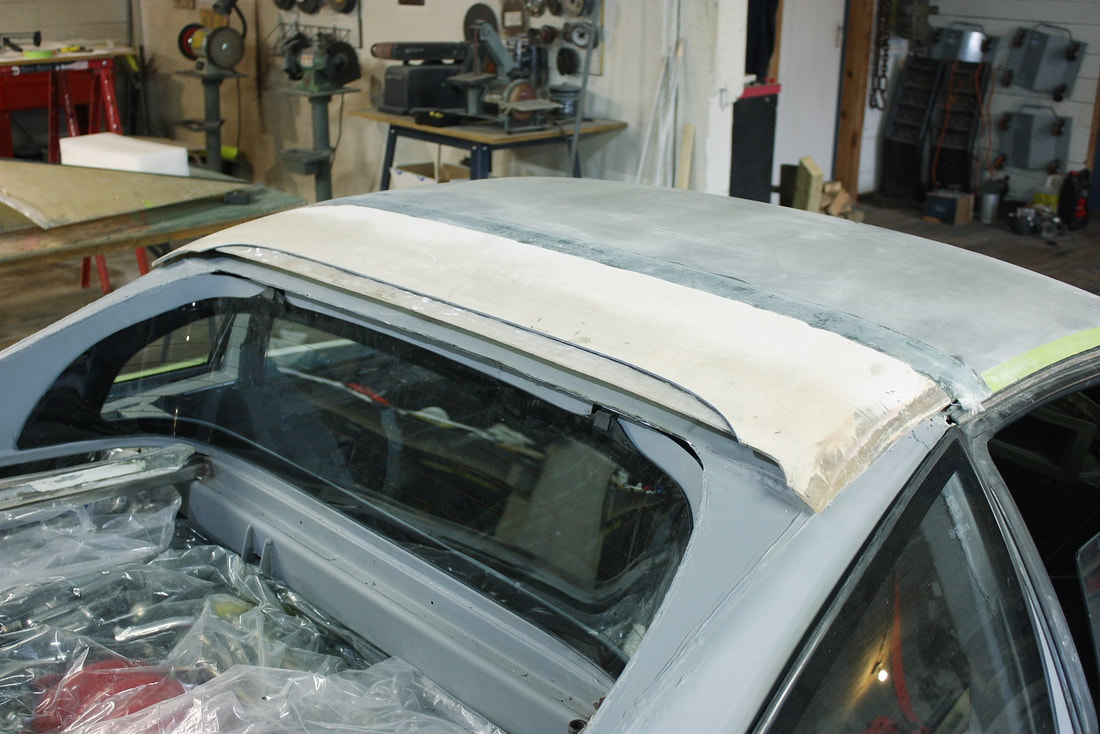
That completed the sail panel reconstruction so the next logical steps were to finalize the roof panel mounts and devise a way to attach the sail panels to the roof, and later, to the fenders. Unfortunately when I shortened the Fiero roof, I cut off part of the OEM reinforcing rib with the embedded anchor nuts (see arrows) that formerly secured the back of the roof to the Fiero chassis:
That completed the sail panel reconstruction so the next logical steps were to finalize the roof panel mounts and devise a way to attach the sail panels to the roof, and later, to the fenders. Unfortunately when I shortened the Fiero roof, I cut off part of the OEM reinforcing rib with the embedded anchor nuts (see arrows) that formerly secured the back of the roof to the Fiero chassis:
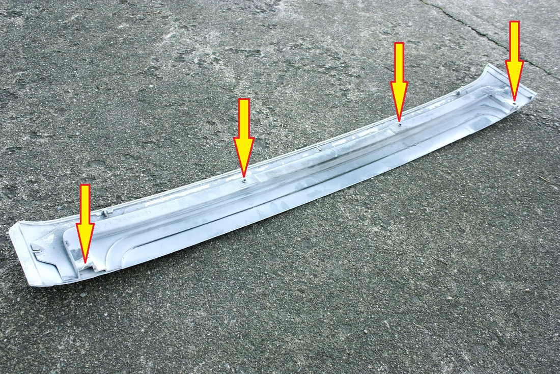
I decided I needed the rib so I ground the Fiero exterior skin off leaving just the rib and the anchor nuts to be reused on my roof:
I decided I needed the rib so I ground the Fiero exterior skin off leaving just the rib and the anchor nuts to be reused on my roof:
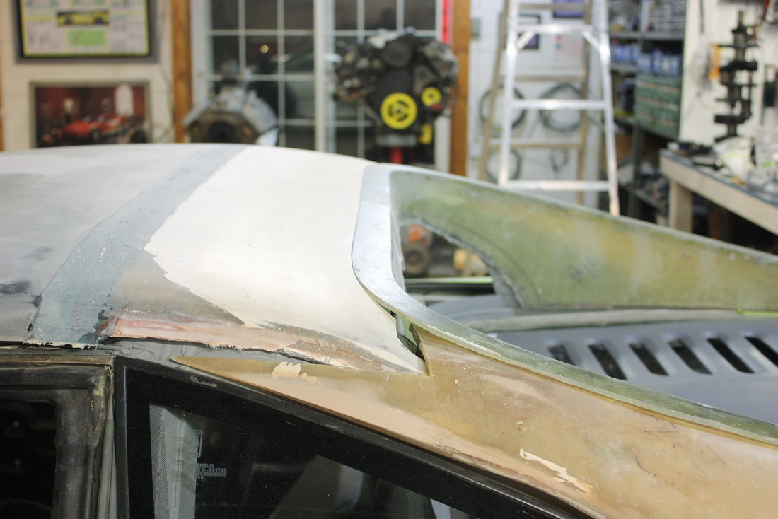
Here’s a wide angle showing how the stiffener follows the sunroof track and how my re-arched roof benefitted from it:
Here’s a wide angle showing how the stiffener follows the sunroof track and how my re-arched roof benefitted from it:
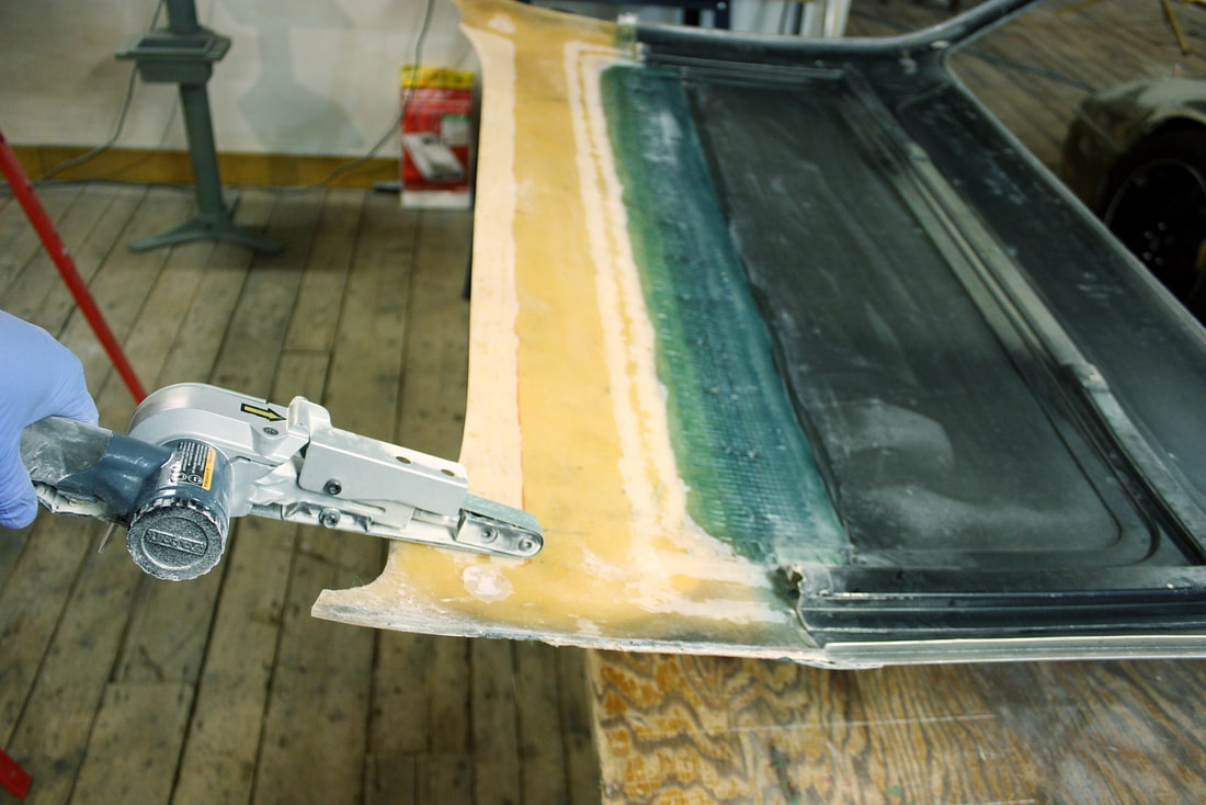
Once I was assured of the fit, I roughened up the rib’s mating surfaces on the underside of the roof to promote good adhesion with the epoxy glue. I used an air powered belt sander with 80 grit paper, and while I was at it, I roughed up the trailing edge of the roof panel as well for the next step:
Once I was assured of the fit, I roughened up the rib’s mating surfaces on the underside of the roof to promote good adhesion with the epoxy glue. I used an air powered belt sander with 80 grit paper, and while I was at it, I roughed up the trailing edge of the roof panel as well for the next step:
Then I simply added the adhesive to both pieces and bonded them together:
Then I simply added the adhesive to both pieces and bonded them together:
Once cured, I was able to solidly bolt the roof to the chassis using the stock front studs, and the new rear nuts. Being able to secure the roof panel to the chassis in the same location with repeatability cleared the way for the next step: to devise a way to align and attach the sail panels to the roof.
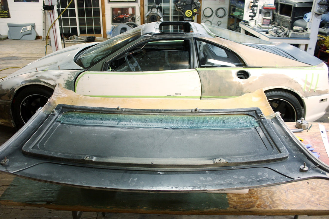
Reattaching the sail panels to the roof would have to be done in several stages, the first being across the back edge, followed by a reattachment at the C-pillars. When I mocked up the photo below, the tops of the sail panels were simply butted up across the rear edge of the roof skin. Clearly a butt joint here would be far too weak to hold the pieces together along the seam:
Once cured, I was able to solidly bolt the roof to the chassis using the stock front studs, and the new rear nuts. Being able to secure the roof panel to the chassis in the same location with repeatability cleared the way for the next step: to devise a way to align and attach the sail panels to the roof.
Reattaching the sail panels to the roof would have to be done in several stages, the first being across the back edge, followed by a reattachment at the C-pillars. When I mocked up the photo below, the tops of the sail panels were simply butted up across the rear edge of the roof skin. Clearly a butt joint here would be far too weak to hold the pieces together along the seam:
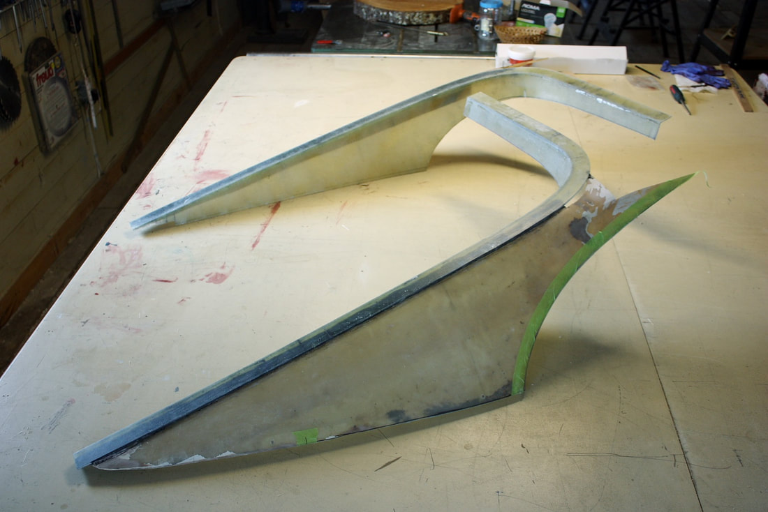
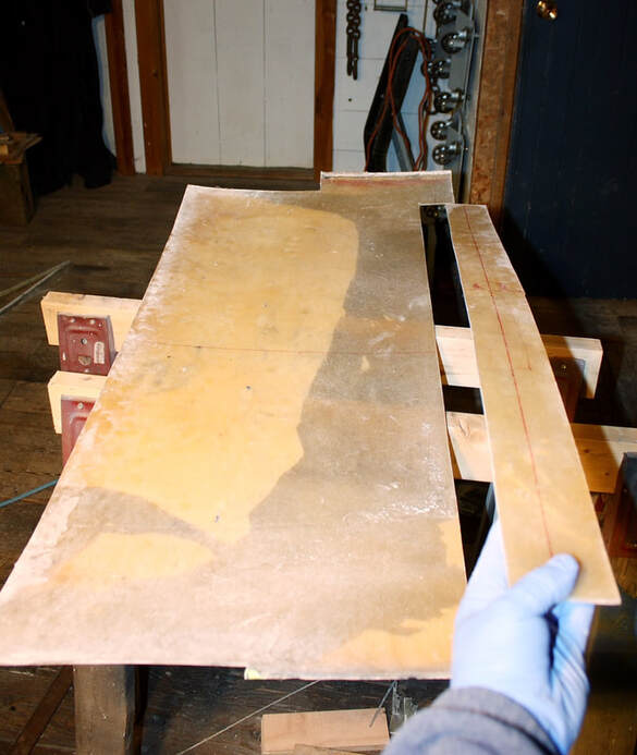
I decided the best way to bond the two edges together was to create a bonding flange glued under the roof skin, such that the sail panels could rest on it across the rear edge of the roof. To make the flange, I once again I turned to my discarded IFG roof section and found it had the perfect curvature and width to do the job. So I cut a 3” wide slice to form the flange:
I decided the best way to bond the two edges together was to create a bonding flange glued under the roof skin, such that the sail panels could rest on it across the rear edge of the roof. To make the flange, I once again I turned to my discarded IFG roof section and found it had the perfect curvature and width to do the job. So I cut a 3” wide slice to form the flange:
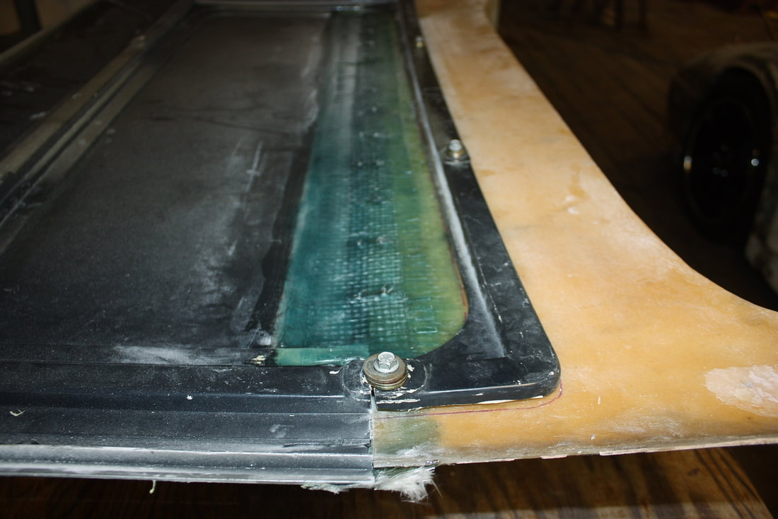
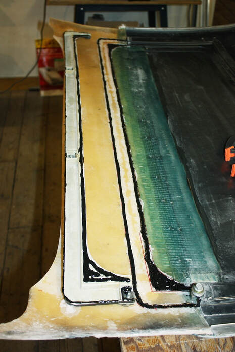
I roughed it up with the belt sander and glued it onto the rear edge of my roof (see three clamps) at the same time as I bonded the aft rib:
I roughed it up with the belt sander and glued it onto the rear edge of my roof (see three clamps) at the same time as I bonded the aft rib:
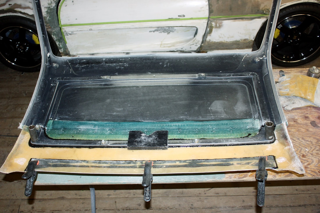
The result is that I ended up with a 1.5” wide flange across the entire width of the roof to bond the tops of the sail panels to:
The result is that I ended up with a 1.5” wide flange across the entire width of the roof to bond the tops of the sail panels to:
Of course more would be needed in the way of glassing the roof and sails together at the C-pillars, but for now this gave me the ability to reliably set the position of top ends of both sail panels.
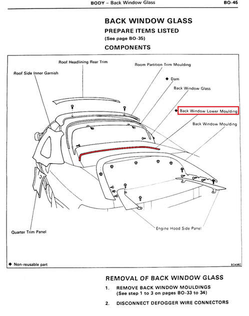
Earlier, I had held off trimming the excess fibreglass around the rear window since I hadn’t received the Toyota MR2 rear window molding I had ordered. From this drawing in the online shop manual, I had expected the molding to be a rigid contoured trim piece that both captured the lower edge of the window and finished the bottom edge.
Of course more would be needed in the way of glassing the roof and sails together at the C-pillars, but for now this gave me the ability to reliably set the position of top ends of both sail panels.
Earlier, I had held off trimming the excess fibreglass around the rear window since I hadn’t received the Toyota MR2 rear window molding I had ordered. From this drawing in the online shop manual, I had expected the molding to be a rigid contoured trim piece that both captured the lower edge of the window and finished the bottom edge.
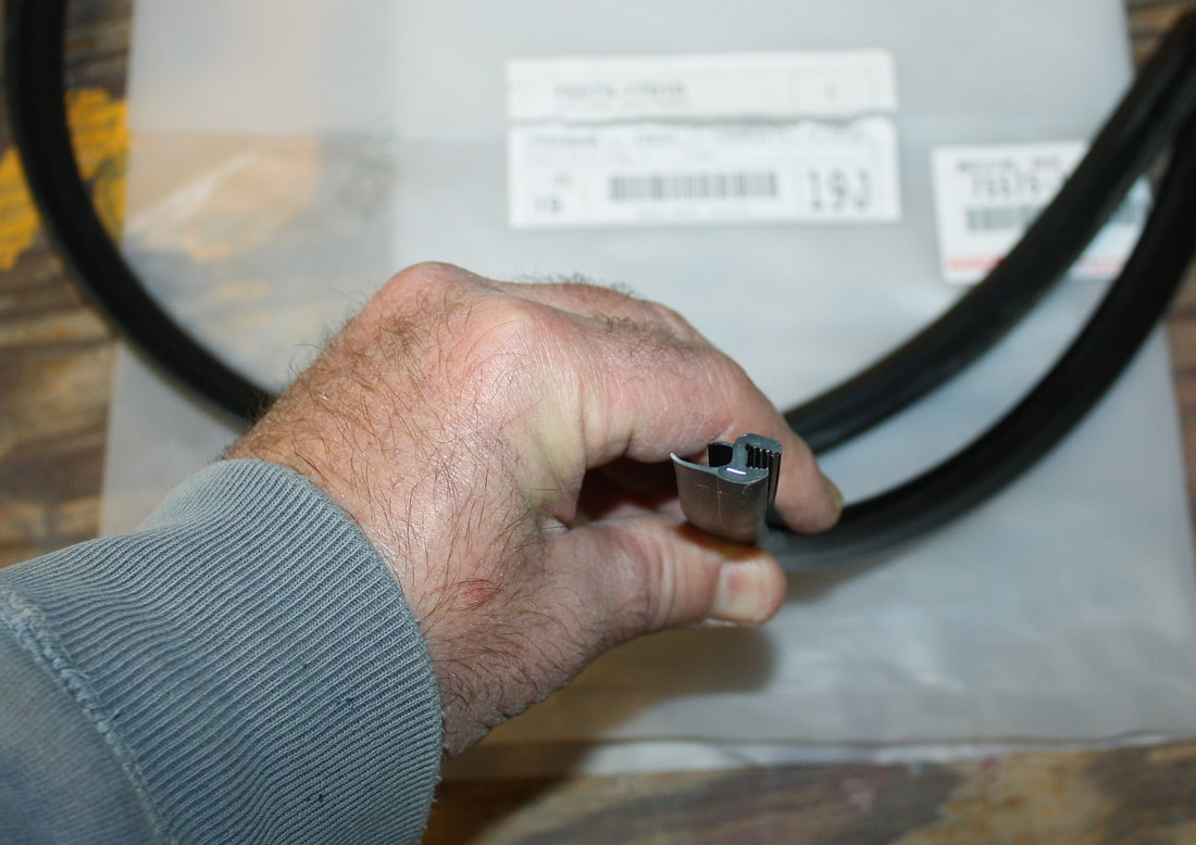
I couldn’t find any good close-up photos of the part on the internet, so I was disappointed when it arrived. It turned out to be a thin flexible rubber seal rather than a substantial rigid molding:
I couldn’t find any good close-up photos of the part on the internet, so I was disappointed when it arrived. It turned out to be a thin flexible rubber seal rather than a substantial rigid molding:
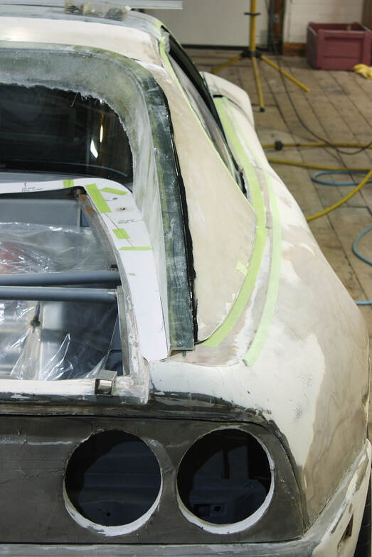
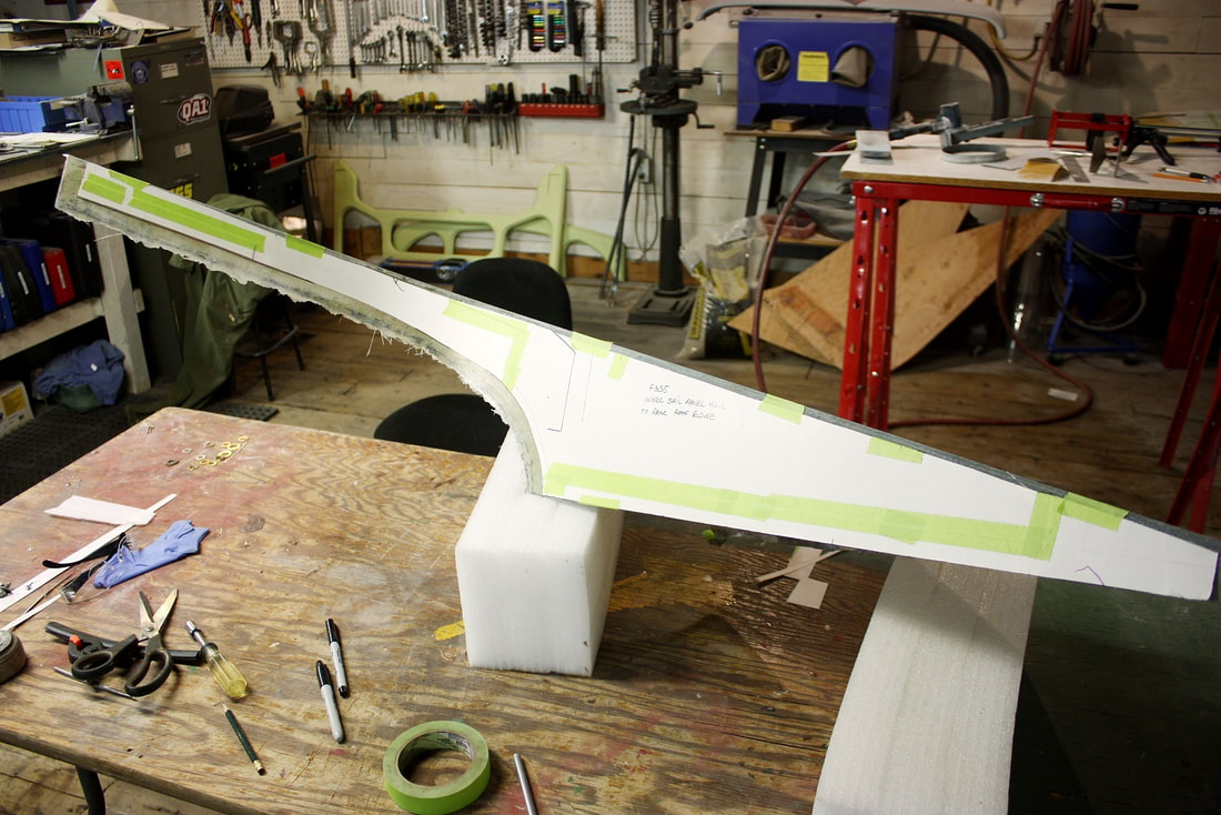
That discovery meant I could now determine the final height of the MR2 window, and trim the sail panels around it accordingly. To get the right contour of the window, I reused my earlier template and marked the inner sail panel wall with a marker:
That discovery meant I could now determine the final height of the MR2 window, and trim the sail panels around it accordingly. To get the right contour of the window, I reused my earlier template and marked the inner sail panel wall with a marker:
Leaving a small margin for final tweaking, I cut the contour of the rear window out using a cut off wheel in my angle grinder:
Leaving a small margin for final tweaking, I cut the contour of the rear window out using a cut off wheel in my angle grinder:
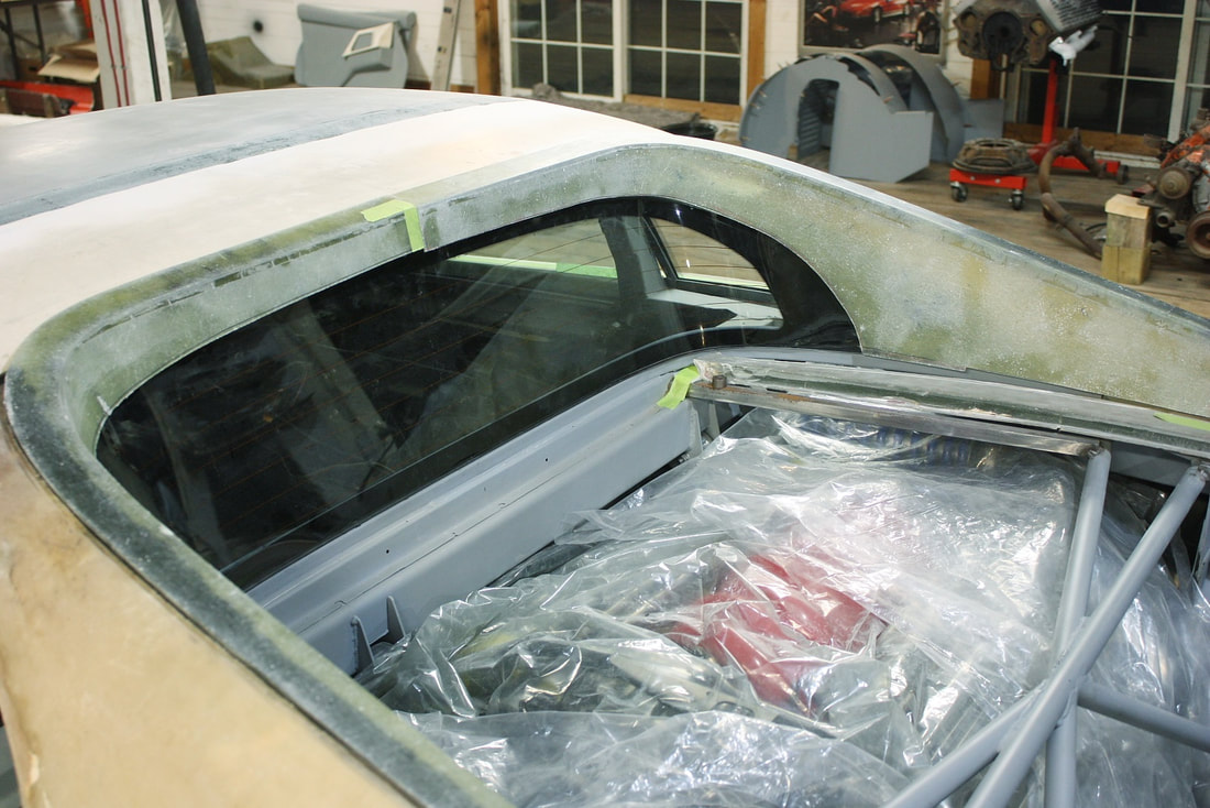
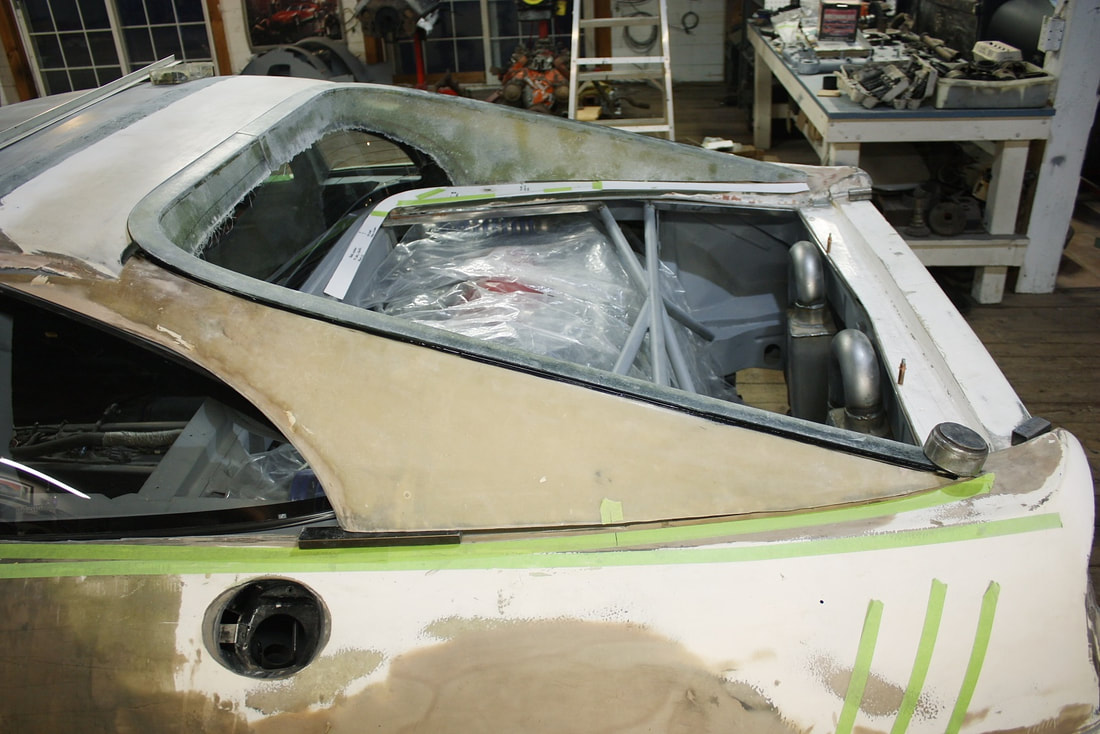
Stepping back again, this is what the result looked like:
Stepping back again, this is what the result looked like:
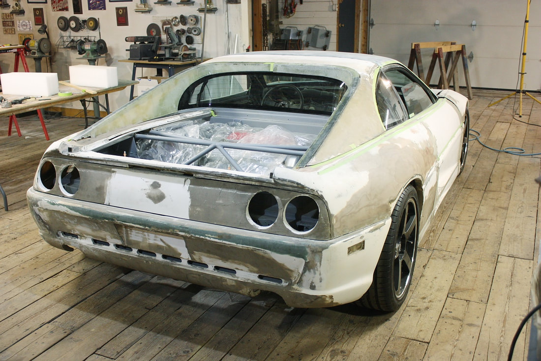
Next up: the sail panel to quarter panel interface.
Next up: the sail panel to quarter panel interface.

 RSS Feed
