When I first started working on the fibreglass shrouds for the radiators, I fully expected to be able to direct some of the cold air from the door scoops to the engine intake. It didn’t work out quite as planned since there were too many things in the way like my rear springs and shocks and fuel filler plumbing. So I gave up on that idea and fell back to Plan B: feed cold air to the engine in a similar way as the authentic Ferrari.
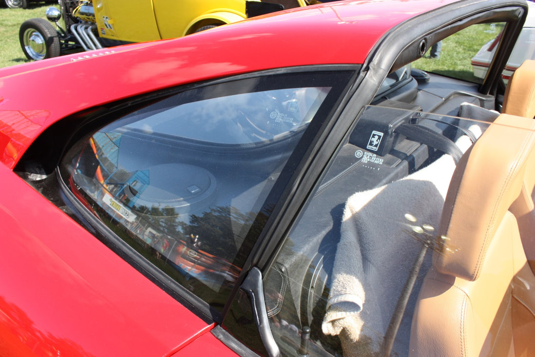
Intake air on the F355 enters into a cleverly hidden opening in the bodywork just behind the rear quarter windows and flows into the hollow C-pillars:
From inside the C-pillars the air is turned 90 degrees inward through duct work and routed into the sides of air filter boxes on either side of the engine bay.
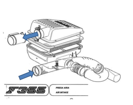
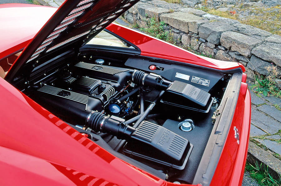
Once filtered, the air is turned another 90 degrees inside the boxes and fed forward to a pair of Mass Air Flow (MAF) sensors, and finally into the two plenums above the engine:
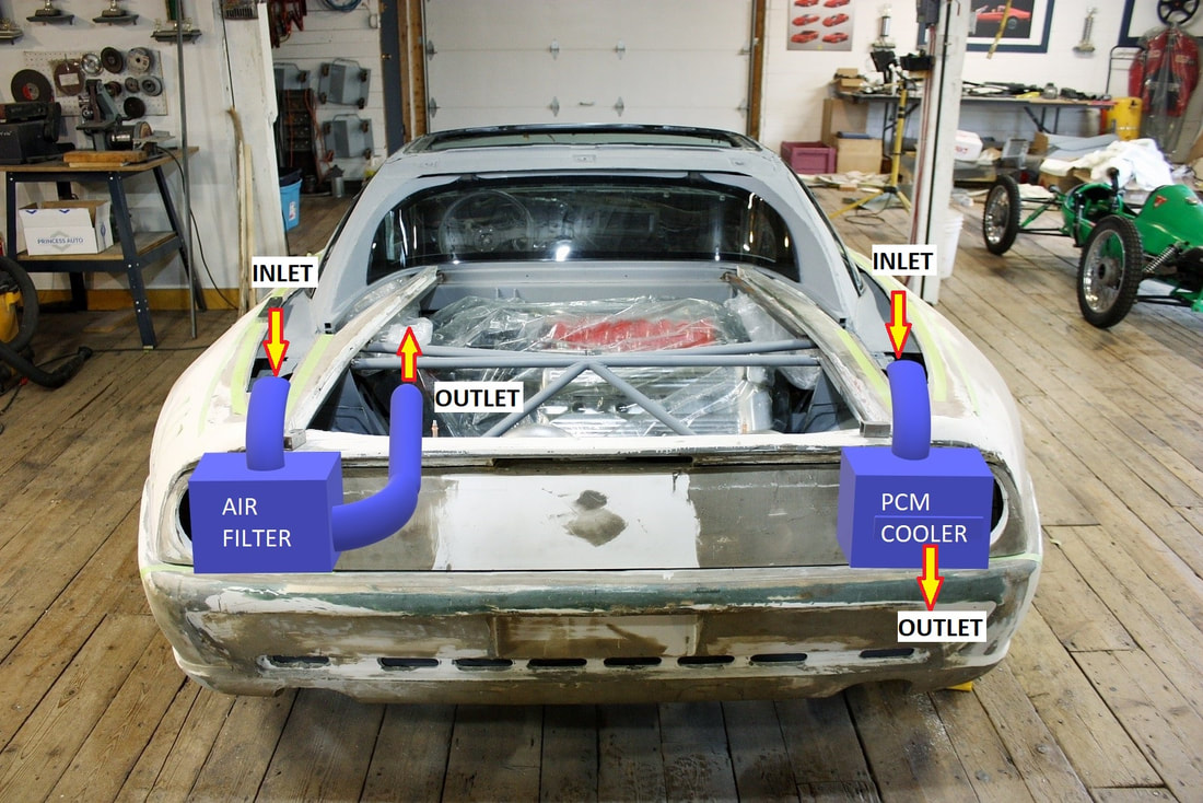
With my engine being transversely mounted, it wouldn’t make sense to have twin filters like the authentic Ferrari because the plumbing from the passenger side filter would have to cross the entire engine bay and would look out of place. So in post #146 I gave a heads up about how I planned to route a Cold Air Intake (CAI) system from the driver’s side only:
When it actually came time to find an air filter housing that would flow enough air to feed a hungry V8, yet small enough for the space I had available, I was temporarily stumped. I spent many hours in the salvage yard looking for modern V8 filter housings without much luck. At first I looked for cars with dual, mirror image housings so I could have symmetrical boxes on either side of the engine bay: one for the filter and one for the PCM. An ’03 Mercedes SL55 AMG looked the most promising, but then I realized there were two boxes feeding the Mercedes’ engine for a reason: one box wouldn’t have flowed enough air.
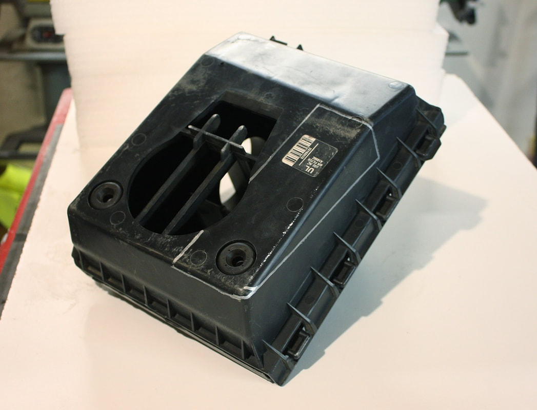
Then I took a second look at the stock 1997 Cadillac Deville air box that came with one of my engines:
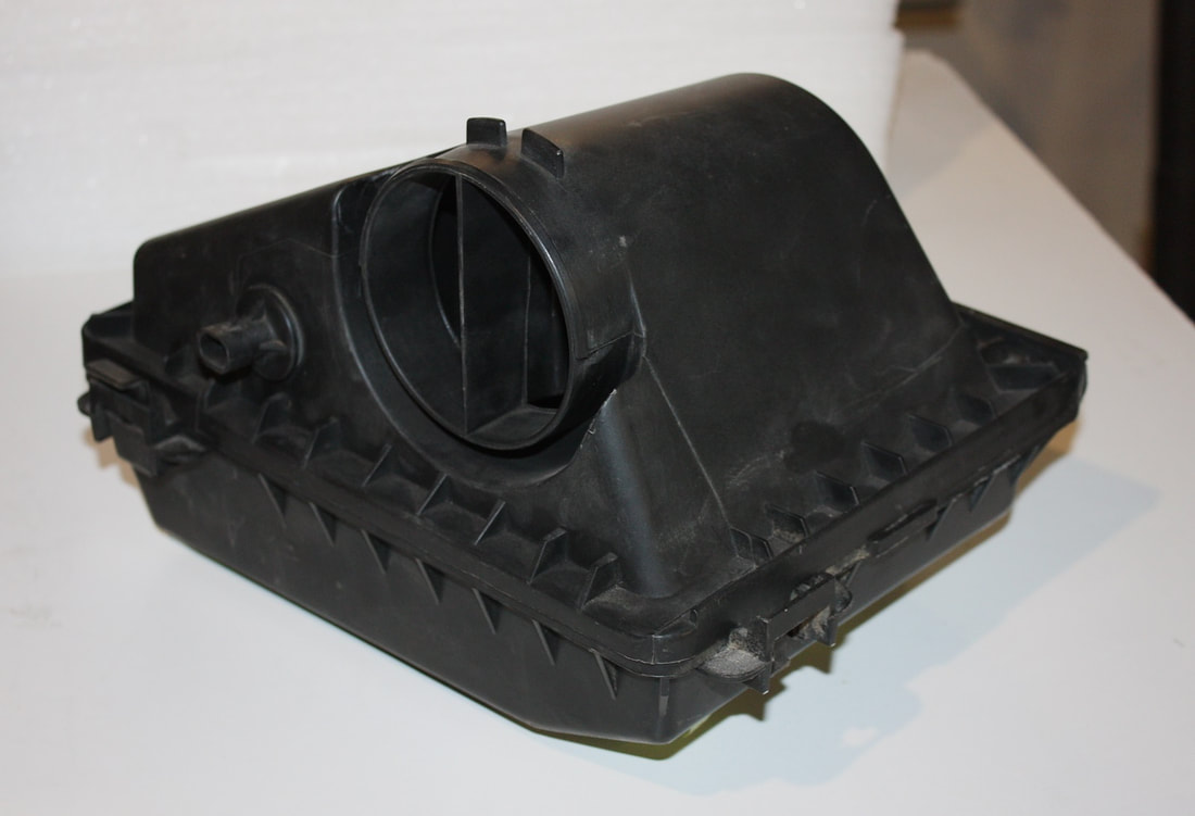
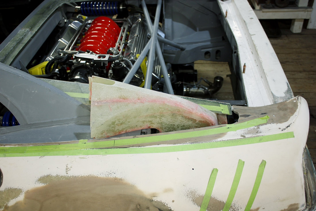
It was obviously sized correctly for the engine, it already had the correct Inlet Air Temperature (IAT) sensor, it turned the airflow 90 degrees within the box, and it was free. After playing around with it in my engine bay, I realized it would fit reasonably well mounted upside-down in the cubby-space I had planned to use:
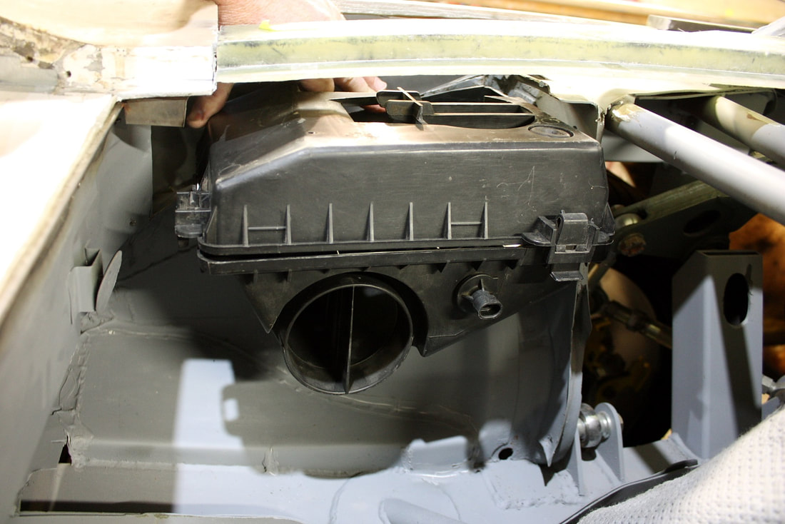
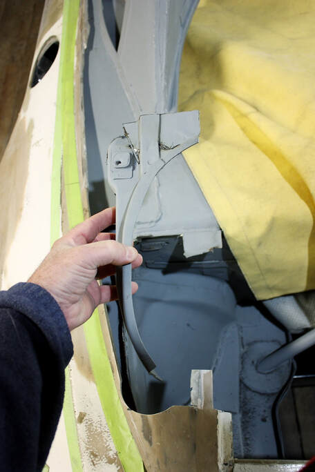
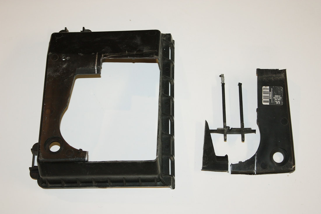
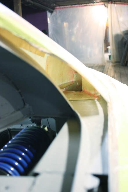
Even though it would be mounted upside-down, the air flow would still be in the originally designed direction with air flowing into the original bottom (now the top), and coming out the side port. One minor problem was that the inlet port fell directly under my new decklid surround. To open up the air path, I trimmed the area of the surround that would be hidden under the sail panel:
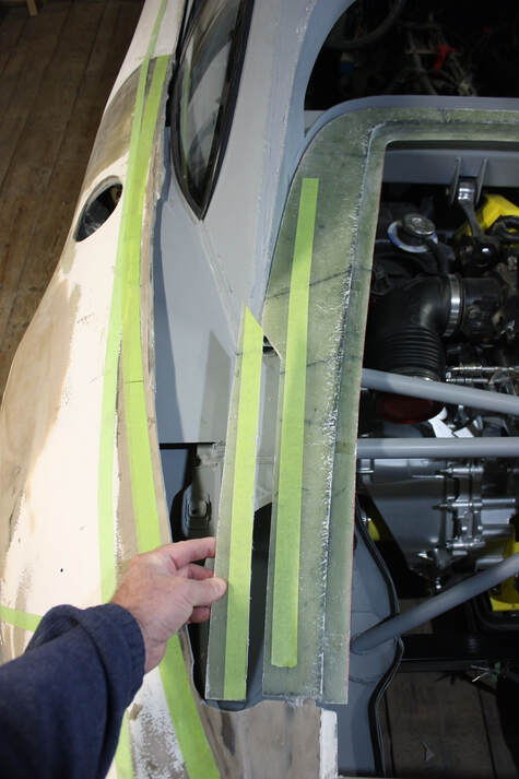
I was getting somewhere with this, but the next obstacle to a clear pathway into the trunk was the old Fiero trunk side wall. The curved wall also prevented me from tucking the square housing as far over as it could potentially go:
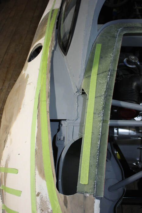
The trunk wall isn’t a structural piece, so I trimmed the offending piece off down to the level of the upper frame rail:
That really opened up the air path to the area where I wanted to install the air filter.
Even though the trunk wall isn’t structural, it still separates the hot air from the radiators that will flow over top of the rear wheels, from the cool air I want around the filter. So rather than simply leave the area open, I made a cardboard template to relocate a new metal wall further outboard and out of my way:
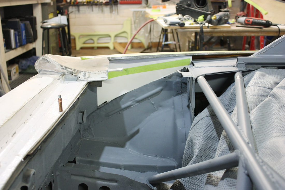
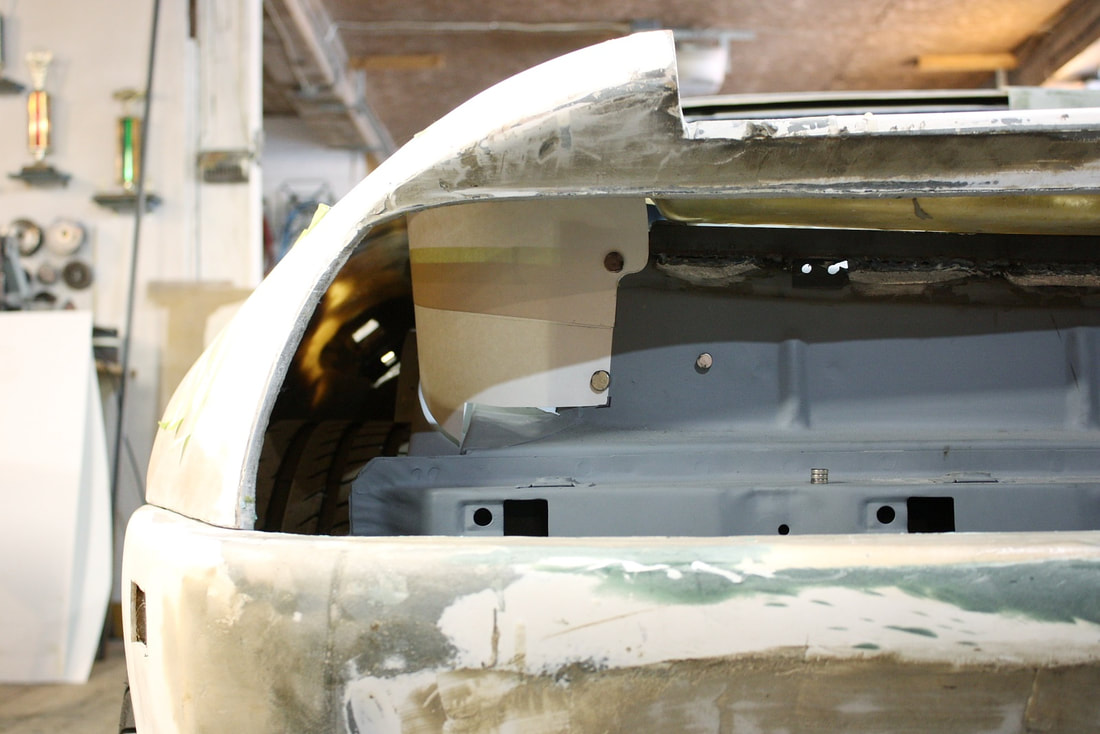
Looking through the tail light panel, here’s how the new trunk wall fits. Rather than being attached to the inboard side of the upper frame rail, it will be attached to the outboard side. (Notice the rest of the tunnel up over the wheel well remains unobstructed for the hot air passing through the radiators and out the tail light panel):
The next step to getting unrestricted air into the filter was to realign the inlet on the filter housing. This next photo shows the stock inlet to the Caddy housing with a silver line showing the cut I needed to make:
I quickly realized I could make the inlet even larger and then used a zippy tool to cut the plastic housing.
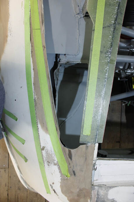
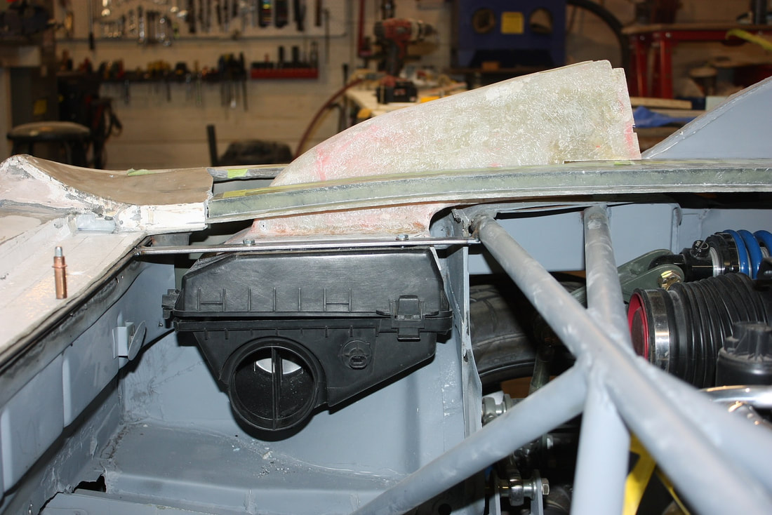
With the mods to the sheet metal trunk, the fibreglass surround, and the filter housing done, I welded a mounting bar between the strut brace and the rear trunk wall and suspended the housing to fix its position:
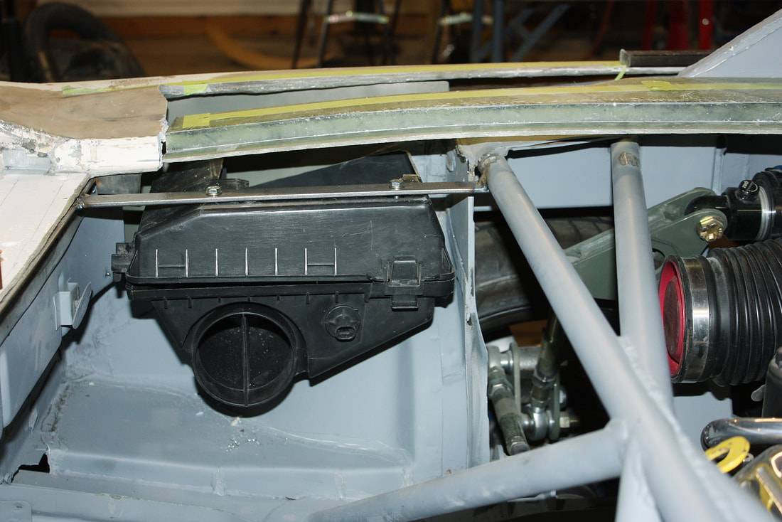
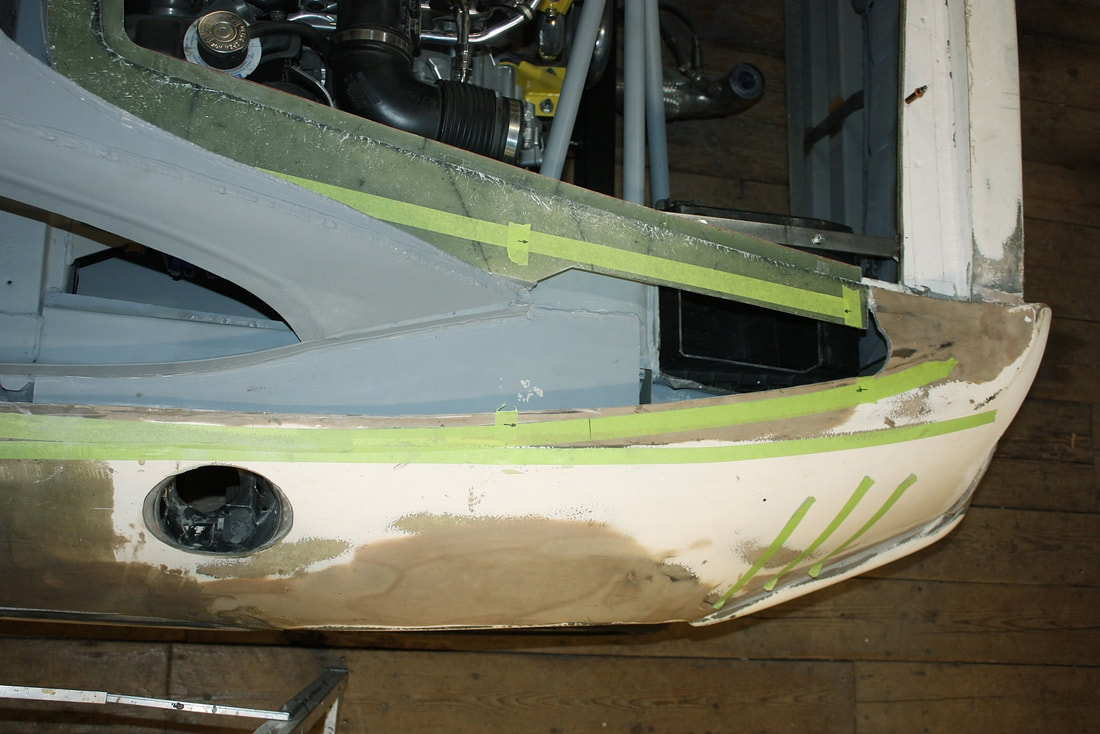
Here’s the top view of the housing inlet through the quarter panel:
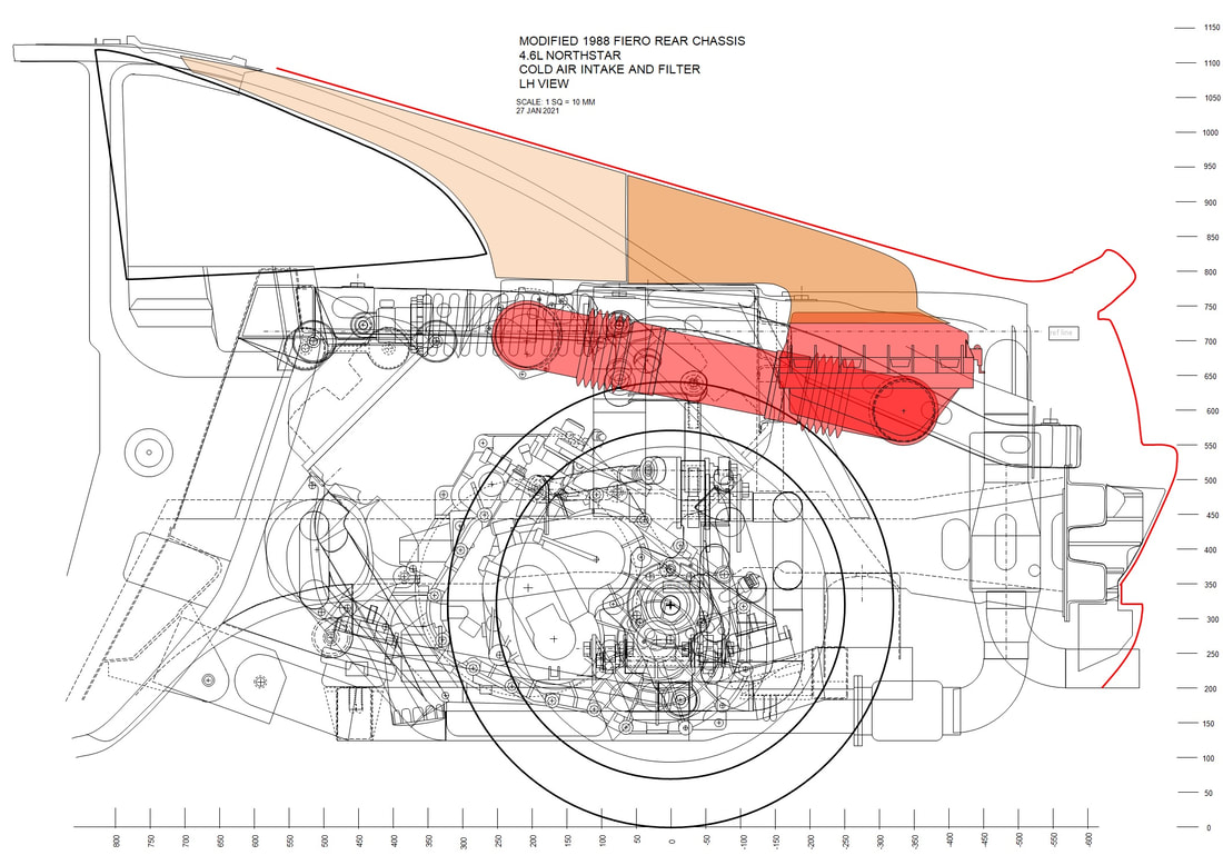
The next step was to come up with a plan to connect the air filter housing to the rear quarter window scoop and to the engine. The drawing below shows how I anticipated doing this. The tan coloured portion is the natural air duct formed by the inside of the C-pillar, and the brown portion is a custom duct shaped to mate with the inside profile of the C-pillar, turn the airflow 90 degrees downward, and seal against the top of the filter housing. The red parts are the filter housing and tubing to the engine inlet:
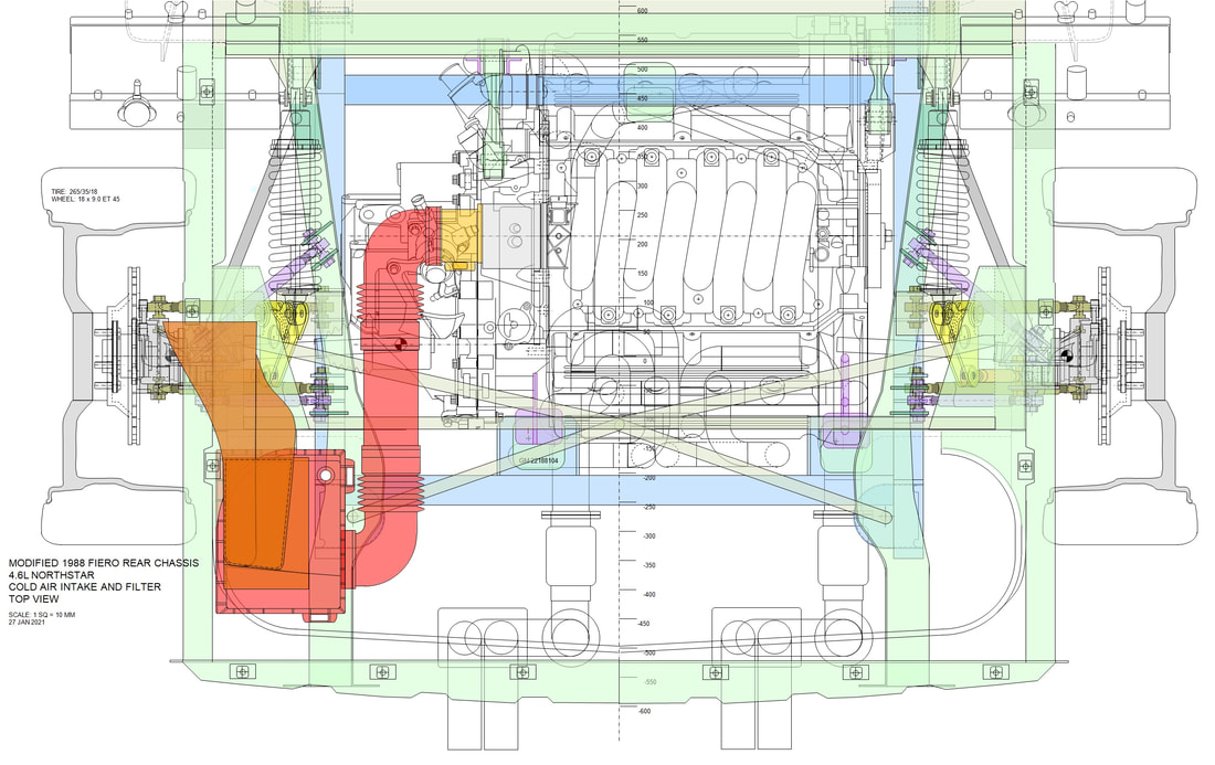
Here’s the top view of the same thing (less the body work) showing how the custom duct had to be offset to funnel the airflow into the filter. I tried to keep the cross sectional area of the duct to a minimum of 67 cm2 at any given point, which matches the area of the engine inlet and will keep the duct from becoming a choke point. The drawing also shows how very conveniently two stock CAI tubes from a Cadillac DeVille will align and mate the air filter to the engine, with only a short section of straight pipe between them:
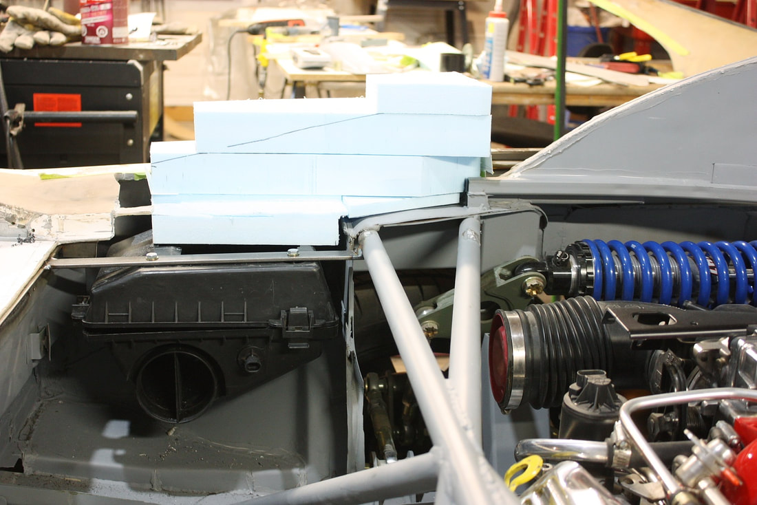
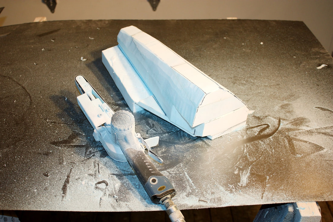
I began building the custom duct next by carving it out of high density Styrofoam in much the same way I made the radiator ducts a while back. I made a base plate from 2” thick foam and worked my way upwards from there:
I stacked three narrower layers of 2” foam on top of the base to get the height I needed to seal against the inside of the C-pillar:
I’ve experimented with several types of glue for the foam but found 3M Super 77 to be super quick, very strong, and best of all it doesn’t dissolve the foam!
I used a band saw to make quick work of the rough cuts, followed by a 1” air-powered belt sander to shape the foam buck to the final dimensions:
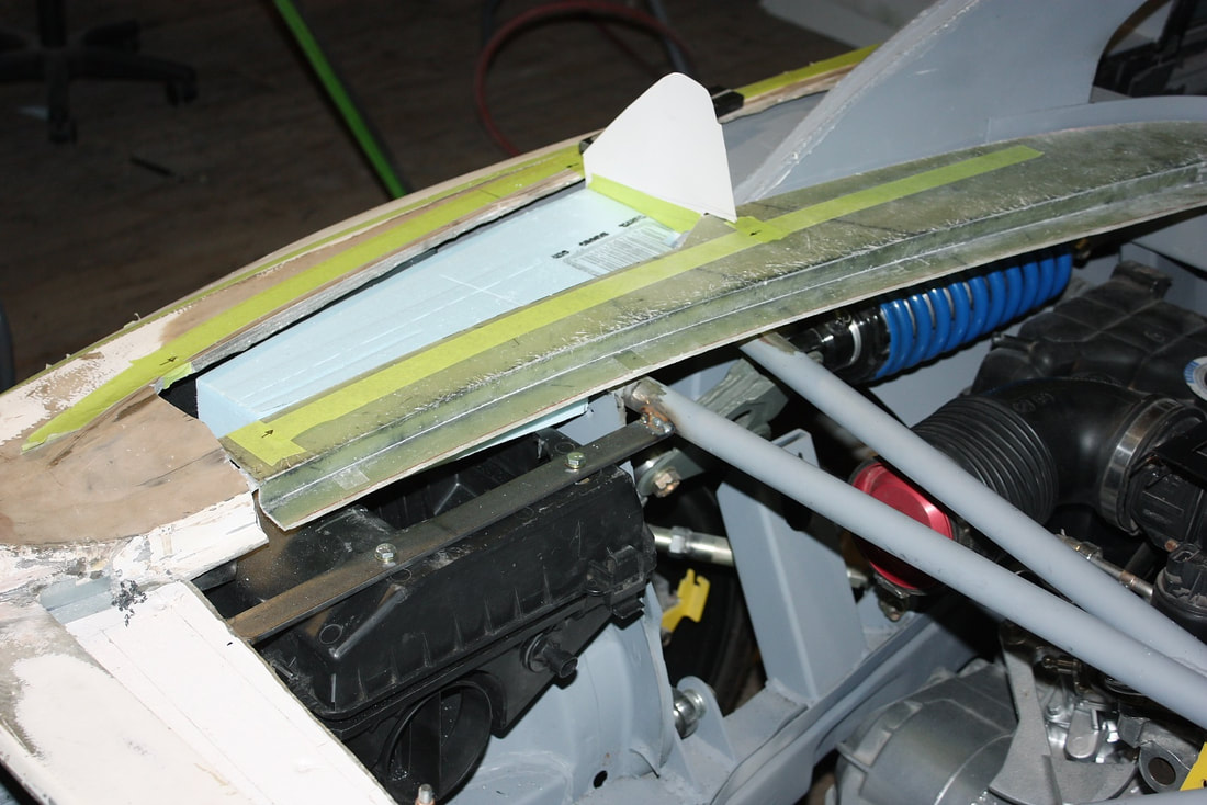
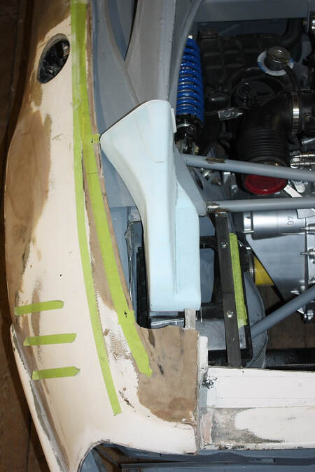
With a few tweaks it fit just right after accounting for the 3/16” layer of fibreglass that would soon cover it. Here’s the top view:
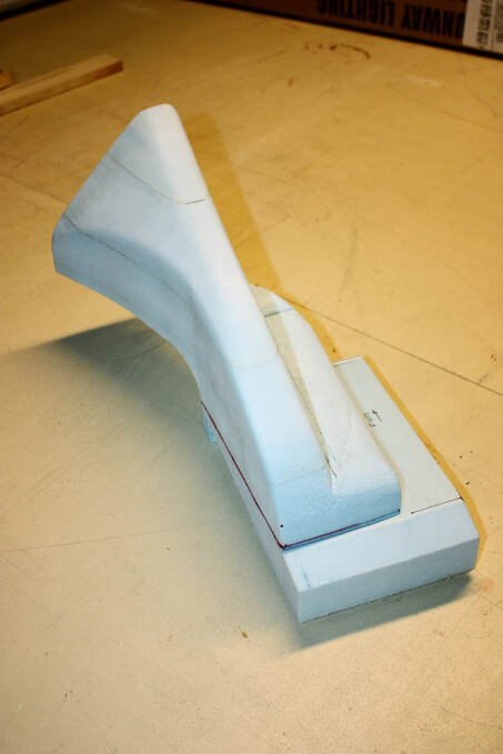
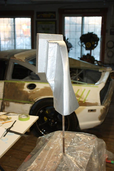
The last step was to add a final foam block to the base to form the mounting flange. Once this last foam piece was glued in place, I couldn’t mock it up anymore because the flange buck was much thicker than the actual flange would be:
Because Styrofoam is made with styrene, and polyester resin has styrene in it, the resin will dissolve the foam unless it’s protected with a barrier of some sort. In the past I’ve used packing tape, but this time I tried aluminium foil duct tape. I covered every square millimeter of the foam, then waxed it thoroughly with a mold release wax:
Then I got busy and laid up the first two layers of fibreglass. Because of the many tight corners and curves on the buck, I started with two layers of light weight woven cloth, which is much easier to work with than mat:
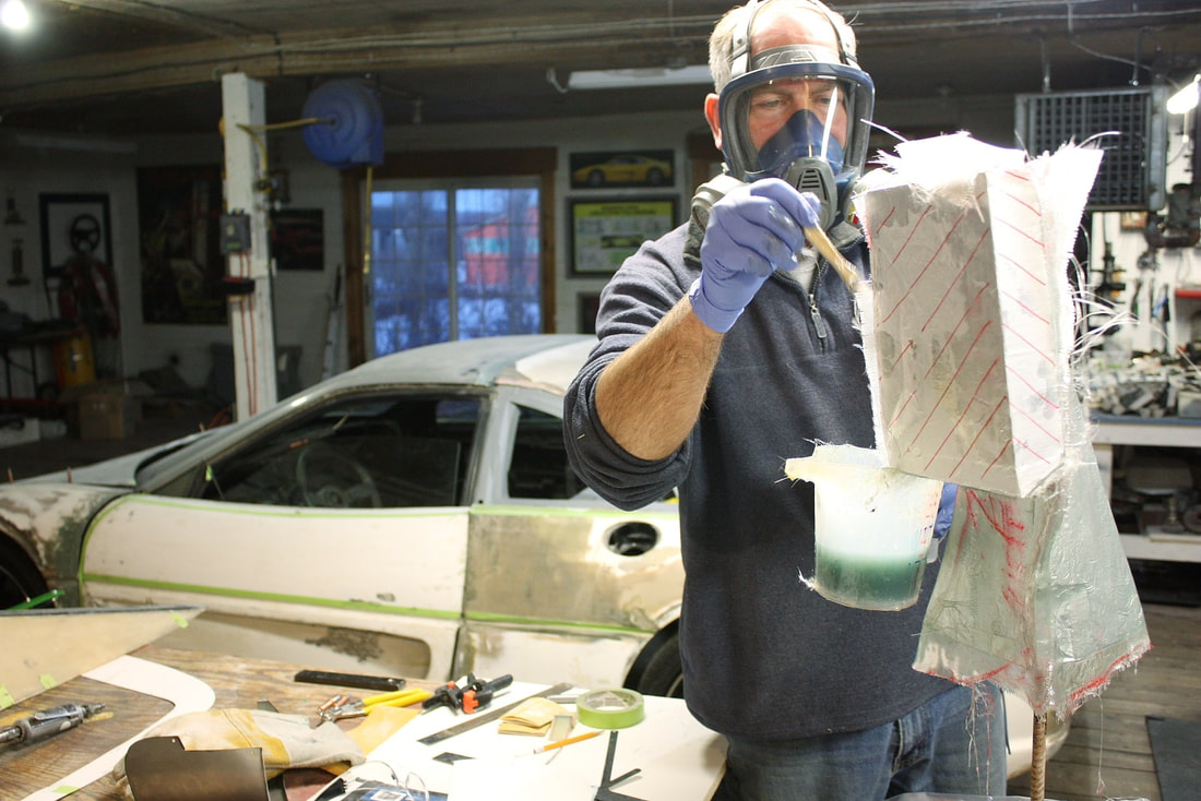
I finished up with an additional two layers of 1.5 oz mat once the cloth layers had set. I could lay the entire duct up with a single piece of cloth, but I had to make four separate pieces for each mat layer to get it to conform to the tight contours:
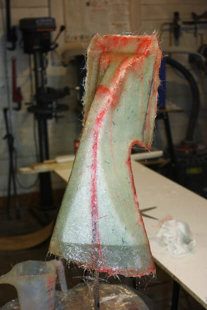
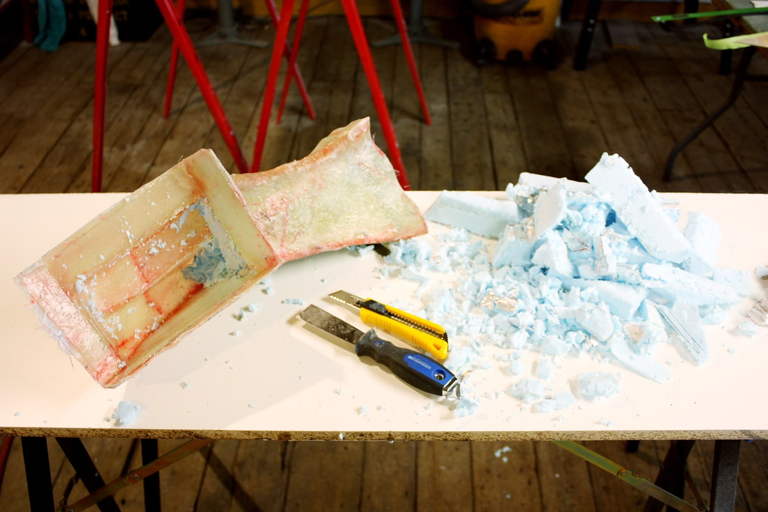
Once the resin had cured, I carved out the foam buck and was left with the one-of-a-kind duct. I found that a flat spade bit in a handheld drill made getting the foam out of the deeper portions of the duct easy, otherwise it was done with a box cutter and a putty knife:
After a little trimming and some fine tuning, the duct fit perfectly:
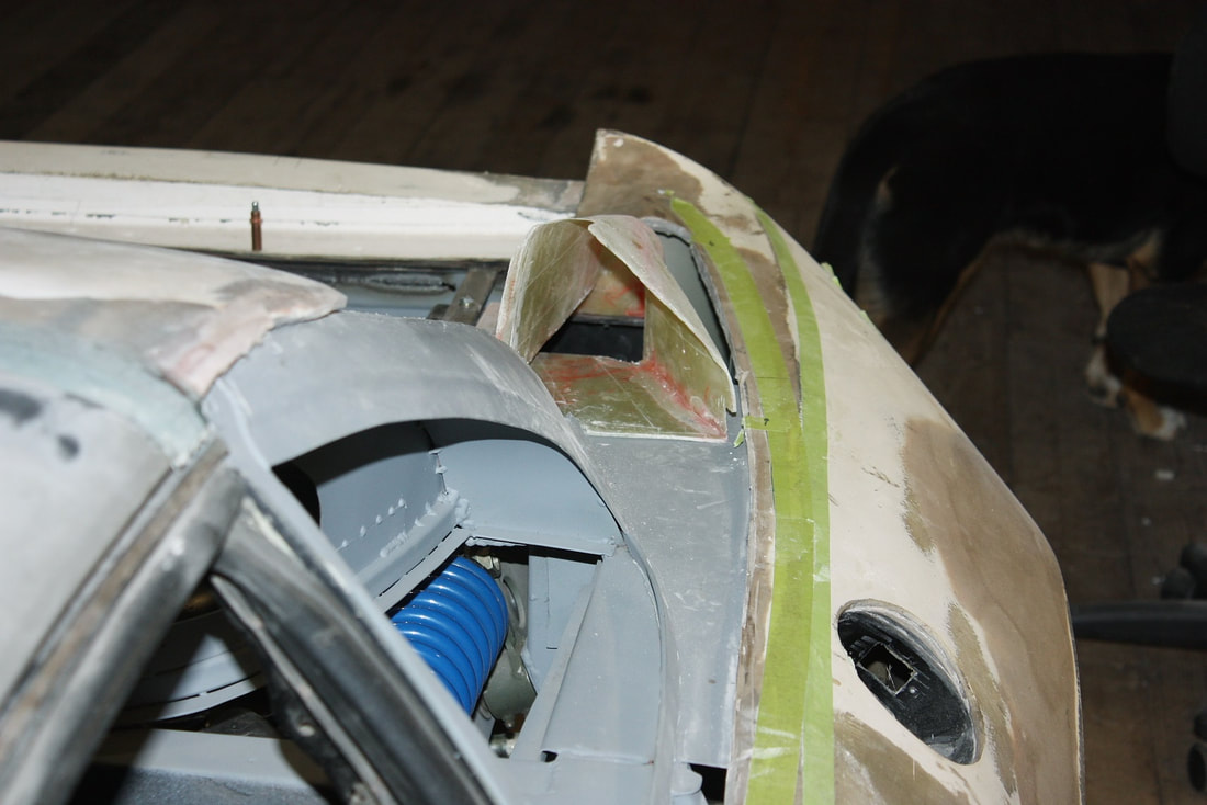
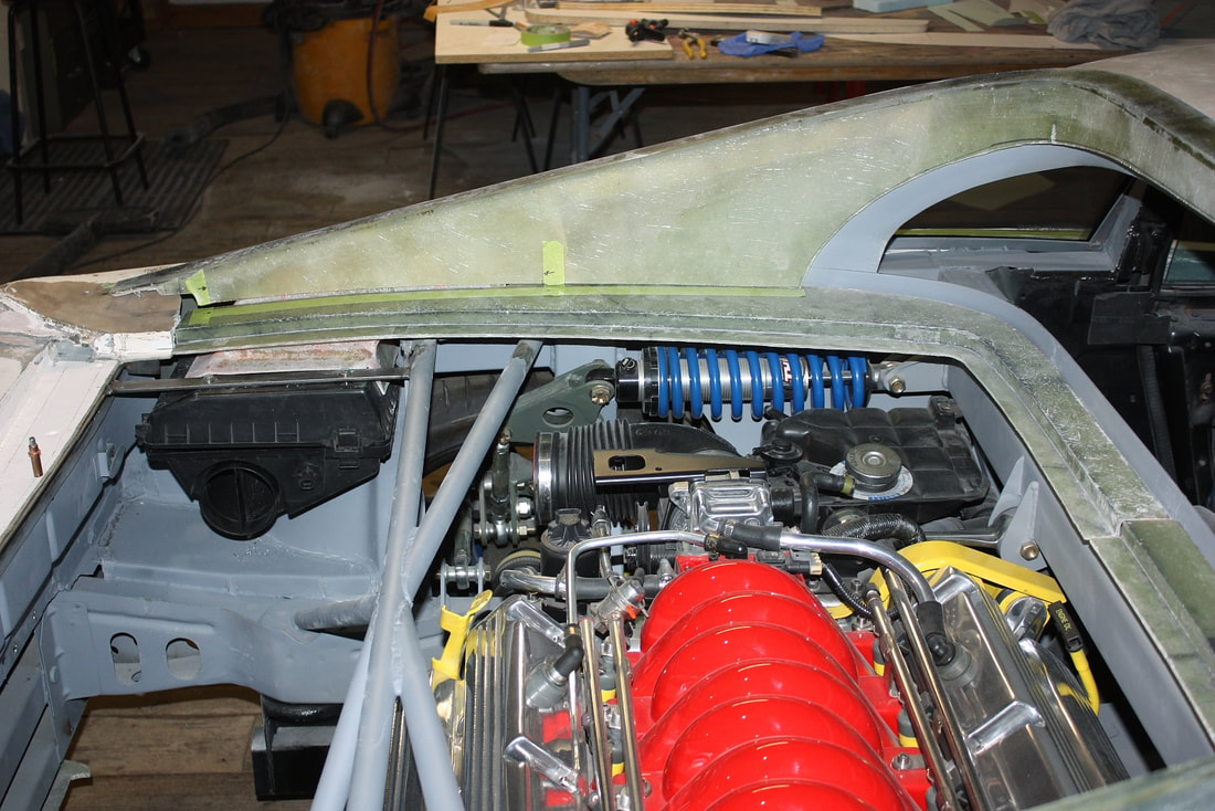
Then I mocked up the sail panel to get some photos of the complete inlet duct including the inside of the C-pillar:
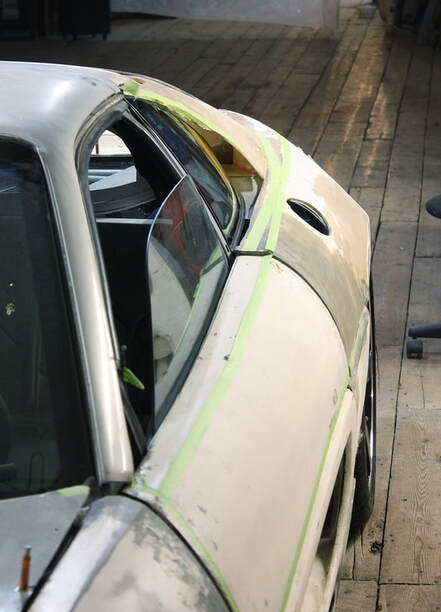
And a shot showing how it all neatly fit under the sail panel:
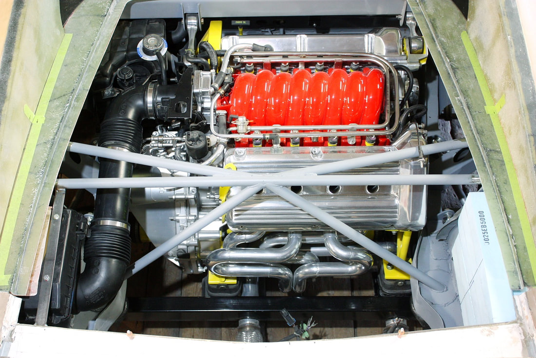
Finally, this photo shows how neatly two Caddy Deville intake tubes line up perfectly with each other between the filter housing and the engine inlet. I just needed a section of straight tube to connect the two:

 RSS Feed
