WHOA! A 150 posts already! It surely must be some kind of record for a build-blog like this. It is starting to get lonely out here in COVID-isolation-land though, so if you're a regular reader of my blog, don't be afraid to post a comment or a question every now and then. Frankly I could use the encouragement.
Anyway, as almost anyone reading this far into my blog will know, the PCM is the computer that runs the engine. In this first photo, the stock 1997 Cadillac PCM is at the top left, and a 2002 fifth generation Corvette PCM is at the bottom right:
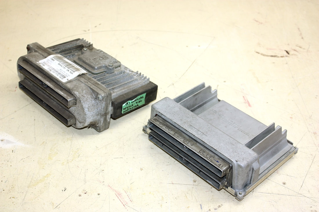
I’ll be using the Corvette computer to run my Northstar (more on that later) but both PCM’s are 2nd generation engine controllers otherwise known as On-Board Diagnostic II (or OBD2). They are significantly more powerful than the OBD1 controllers before them, so much so that many OBD2 controllers are equipped with cooling fins and are located in an area with lots of airflow to keep the electronics happy, as these two are. For example, the stock Northstar controller is mounted in a plastic box directly in the ductwork of the engine intake, and the Corvette’s PCM sits in the cold area behind the passenger side front wheel well where it’s protected from the heat of the engine bay.
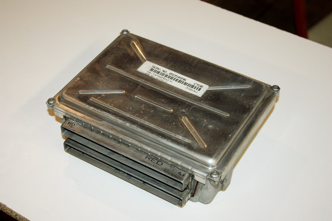
Here’s the flip-side of the Corvette PCM:
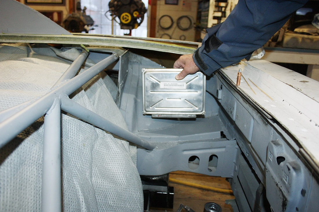
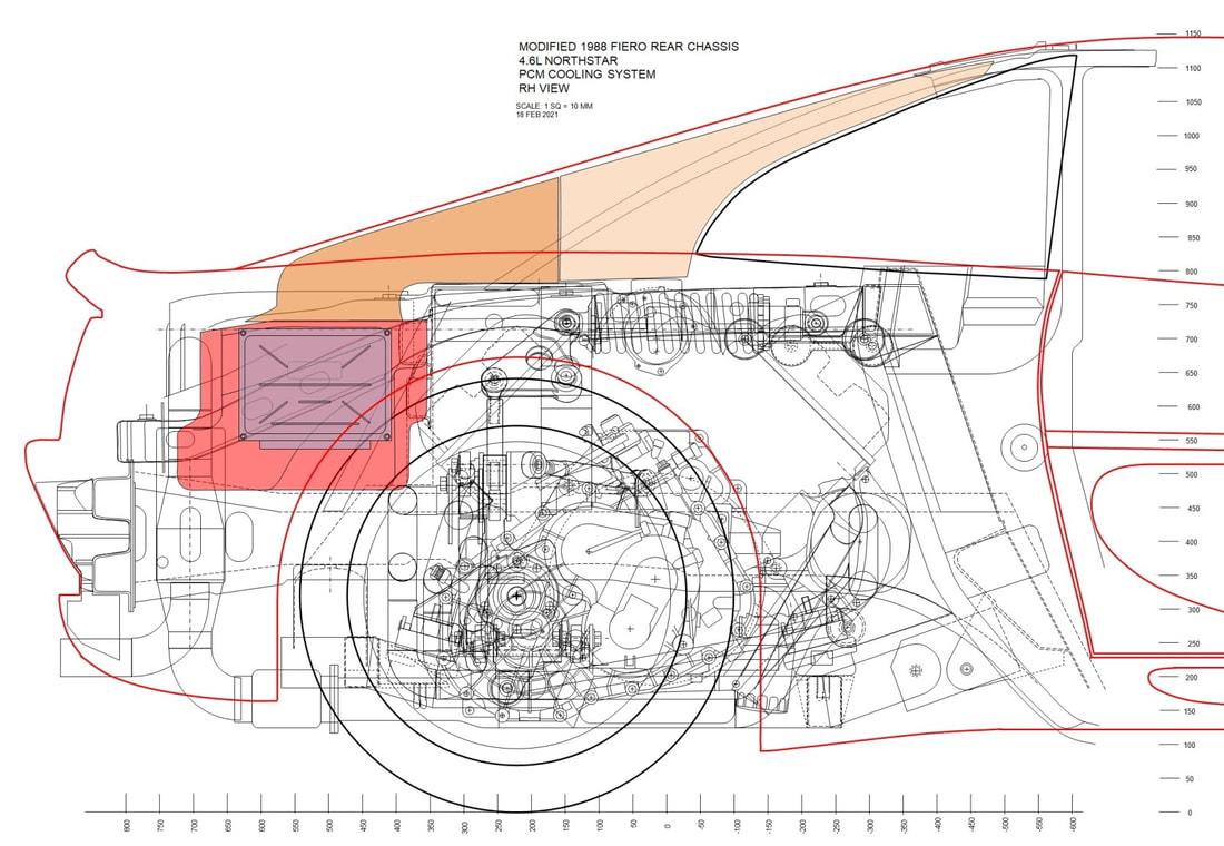
While many people mount later model PCM’s in the stock Fiero location inside a small compartment between the seats in the passenger cabin, I decided the Corvette PCM wouldn’t be happy there. I decided to mount the new controller where there would be lots of cooling airflow. As mentioned in an earlier post I planned to install it opposite the engine air filter housing in the airstream entering the engine bay from the C-pillar scoop on the passenger side:
To some, this might seem like overkill, but if I can keep this extremely important piece of already-obsolete electronic equipment from experiencing a premature death, then it will be well worth the extra effort now. Besides, mounting it out back will free up space in the cabin, and if designed right, will make accessing the PCM easier too.
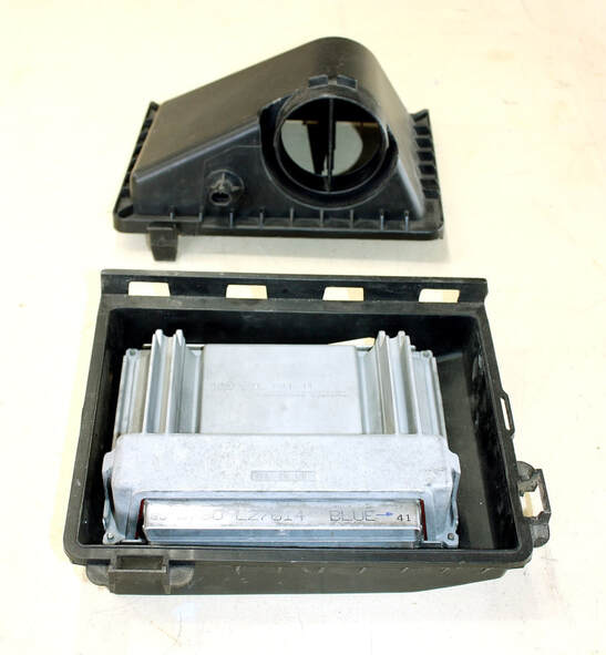
The next step was to find a suitable box to install the PCM inside to funnel the airflow over the fins. At first I’d hoped to install the Corvette controller inside the stock Caddy PCM box, but it didn’t’ fit well, and the box really wasn’t aesthetically appealing. Next, I considered buying a second Caddy air filter housing to install it in, keeping both sides of the engine bay symmetrical:
The PCM miraculously fit inside, but in only one orientation, which left no room for the large electrical connectors, and a poorly located exhaust port. After brainstorming several other ideas, I realized I’d have to design a custom PCM housing, so I drafted some drawings of what I thought would be the ideal PCM box with provisions for intake air, exhaust air, an access panel, and room for an electrical harness long enough to pull the PCM out of the box to make connections easier:
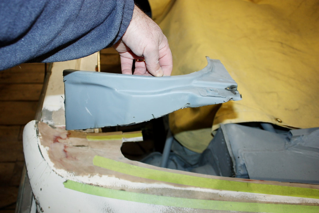
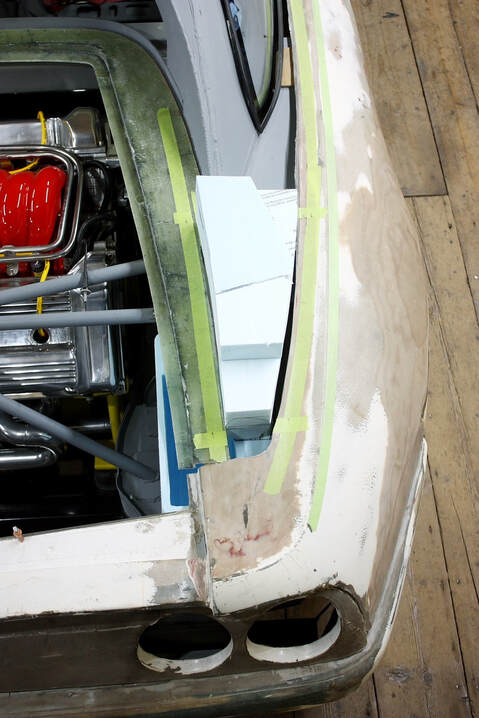
Many of the same processes that were required for the engine intake were also required for the PCM housing, such as cutting out the Fiero trunk wall and moving it further outboard:
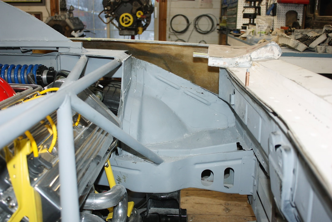
This next photo shows the trunk sidewall has been removed, but also shows the complex shape of the area for the new housing. There’s a bulge for the wheel arch that intrudes into the space, as well as a vertical “rib” just in front of the bulge. I’d have to get creative to build a box to fit those contours:
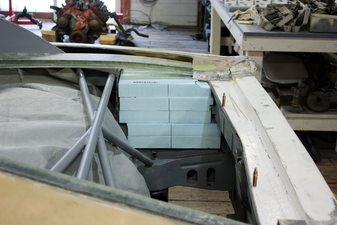
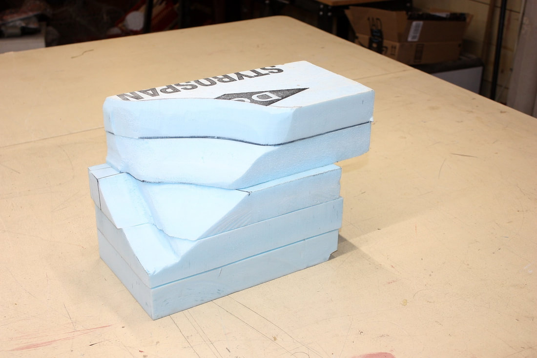
I started by measuring the area, then cutting and stacking a bunch of Styrofoam blocks on my work bench, and gradually carved out the relief for the wheel arch and vertical rib:
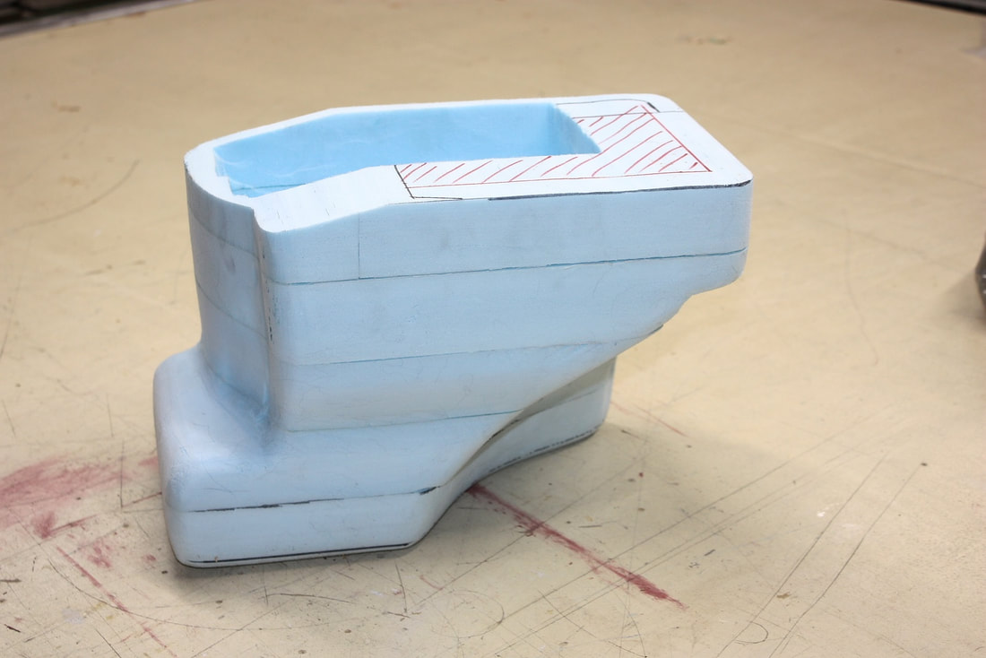
Here’s what the rough foam buck looked like from the underside:
Once the rough shape was eked out, I smoothed it over to give it less of a cave-man crudeness look:
With the cooling box buck mostly finished, I focused on stacking foam to build the buck for the air scoop connecting the box to the quarter window opening:
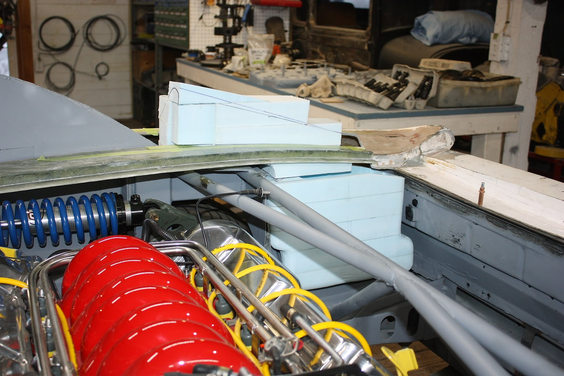
Even if I’d been able to save the foam buck from having made the air filter scoop, it would’ve been useless since I needed its mirror image for the PCM scoop. Here’s the strategically piled foam starting to take shape:
Once the scoop was carved and smoothed over, I prepped both pieces with tape to protect against melting from the polyester resin. I covered the scoop with aluminium foil tape to see if it would be any easier to form around compound curves, but the jury is undecided:
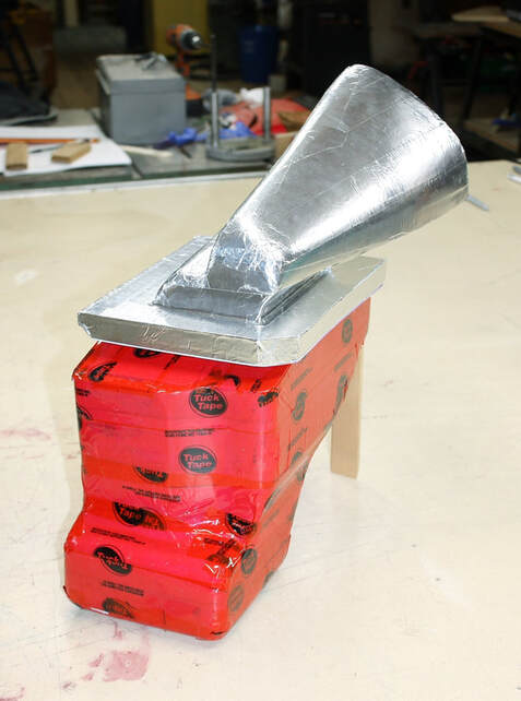
I greased up both pieces with a generous amount of mold release wax to seal off any small pinholes and tape joints as well as to help pull the foam out of the fibreglass later on:
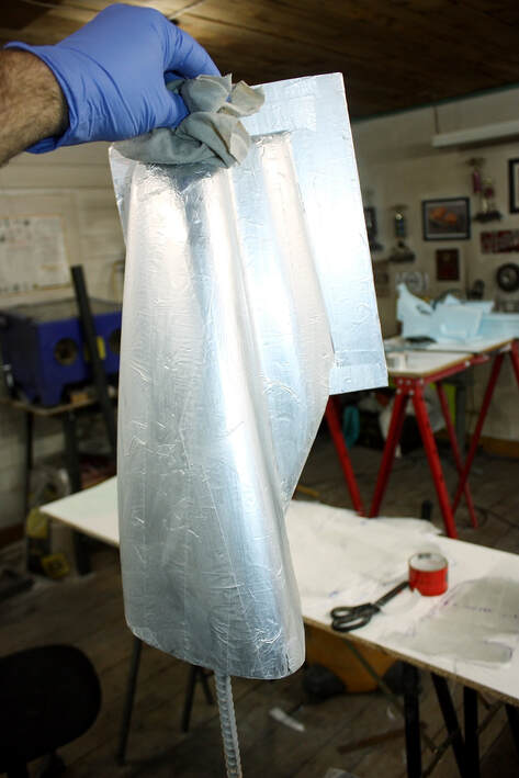
I laid up the scoop and box with two layers of lightweight fibreglass cloth followed by another two of 1.5 oz mat since the cloth conforms to the complex curves much better than mat. I also learned that laying up a six-sided cube isn’t possible in one fell swoop: five sides can be done but if turned to lay up the sixth side, the cloth sags and falls off the side facing down:
Here’s the housing ready to ‘glass up the sixth side… in this case, the top:
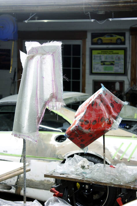
As with the driver’s side scoop, the only way to remove the foam from the PCM scoop was to dig it out. Again, I found that a 1” spade bit in my handheld drill worked well to chip out the foam quickly without hurting the fibreglass:
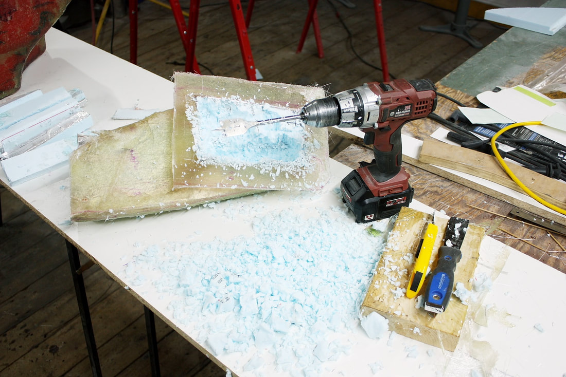
If repetition makes one an expert at something, I was well on my way to becoming a guru at molding compound shapes, though it still takes far more time than planned.
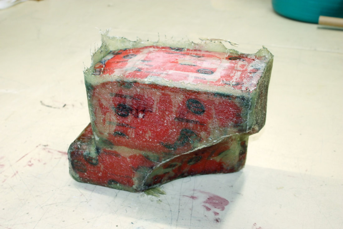
With the excess flashing trimmed off and cleaned up, I mocked up the PCM cooling box and air scoop into place and checked clearances and fitment. Both needed some tweaking to sit properly. Multiple layers of fibreglass on a male buck always tend to make things larger than expected, and rounded corners always bulge out more than they should:
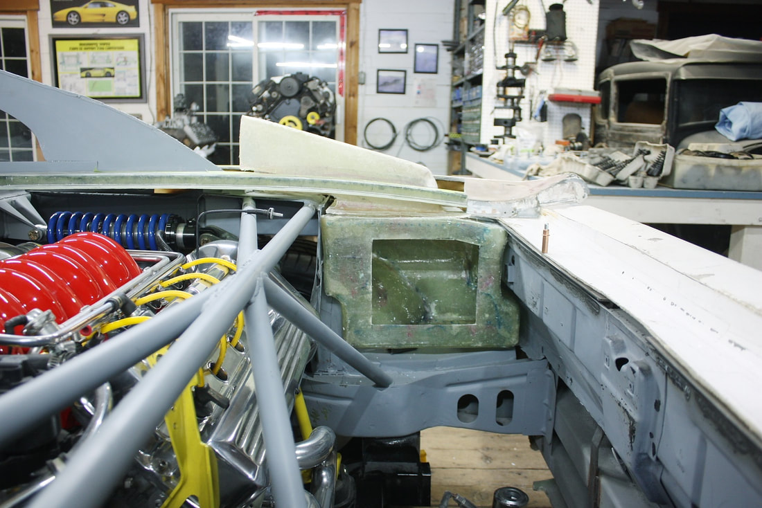
Next up, I needed to mount the PCM, direct the airflow through the box, and protect it all from the heat of the nearby exhaust system.

 RSS Feed
