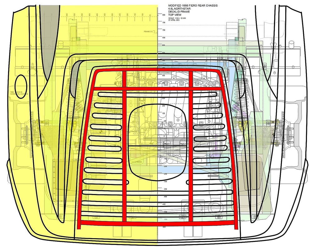
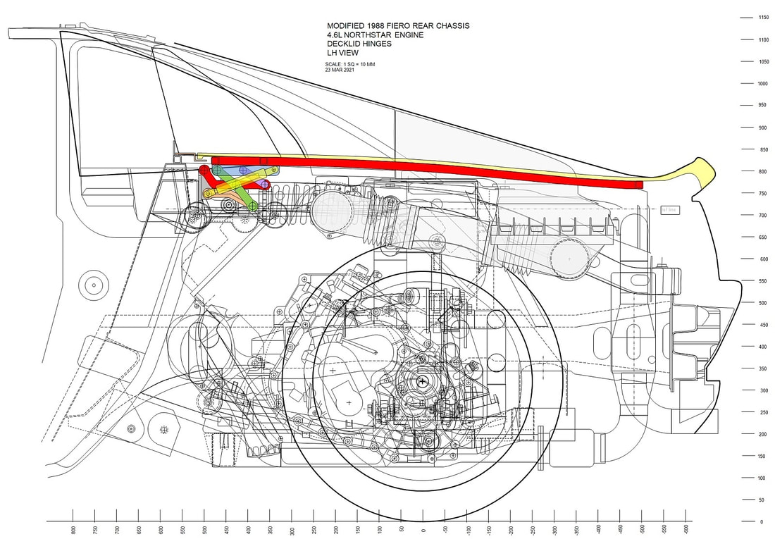
I laid out a plan in my last post to build a perimeter frame for the deck lid similar to the authentic Ferrari. It was designed to provide mounting points for the hinges and the latch, to provide structural rigidity to the single layer outer skin, and in my case, to counteract a warp in the skin panel. I’ve already shown this drawing but here is a refresher of the plan:
I laid out a plan in my last post to build a perimeter frame for the deck lid similar to the authentic Ferrari. It was designed to provide mounting points for the hinges and the latch, to provide structural rigidity to the single layer outer skin, and in my case, to counteract a warp in the skin panel. I’ve already shown this drawing but here is a refresher of the plan:
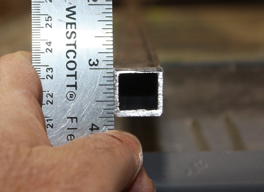
The clearance between the top of my new hinges and the bottom of the deck lid automatically limited the maximum size square tubing that I could use for the perimeter frame to ¾”. I chose 14 gauge (0.083”) wall thickness to keep things light, and to make it easier to bend to shape:
The clearance between the top of my new hinges and the bottom of the deck lid automatically limited the maximum size square tubing that I could use for the perimeter frame to ¾”. I chose 14 gauge (0.083”) wall thickness to keep things light, and to make it easier to bend to shape:
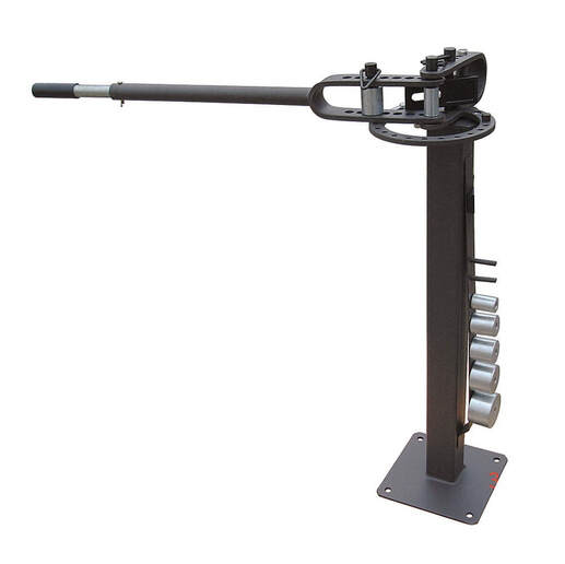
The tight 3.5” radius at the front corners of the frame required the leverage of a floor mounted tubing bender, much like this one:
The tight 3.5” radius at the front corners of the frame required the leverage of a floor mounted tubing bender, much like this one:
But a machine like the one above can’t properly bend square tubing without specific dies. When square tubing is bent, the outside wall has to stretch significantly while the inside wall must be shrunk. But shrinking the metal as much as it would need to be isn’t possible, so the extra metal must be displaced toward the inside of the tube, reducing its cross section. Dies like the ones below were used to make the tight bends at the front corners of my frame:
But a machine like the one above can’t properly bend square tubing without specific dies. When square tubing is bent, the outside wall has to stretch significantly while the inside wall must be shrunk. But shrinking the metal as much as it would need to be isn’t possible, so the extra metal must be displaced toward the inside of the tube, reducing its cross section. Dies like the ones below were used to make the tight bends at the front corners of my frame:
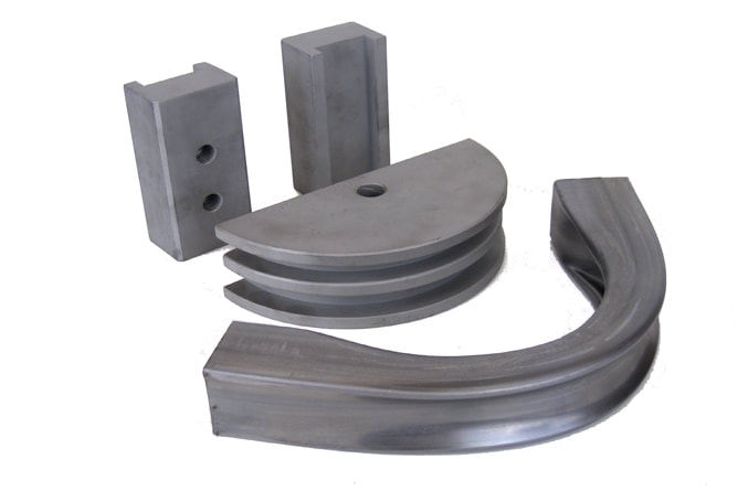
The center rib in the circular die pushes the inner wall toward the center of the tube giving the characteristic dented inner wall, while the outer two ribs of the die prevent the upper and lower walls from bulging outward while this is happening:
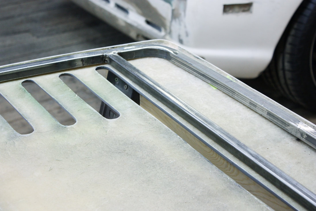
Here’s a close up of the first bend in the perimeter frame:
The center rib in the circular die pushes the inner wall toward the center of the tube giving the characteristic dented inner wall, while the outer two ribs of the die prevent the upper and lower walls from bulging outward while this is happening:
Here’s a close up of the first bend in the perimeter frame:
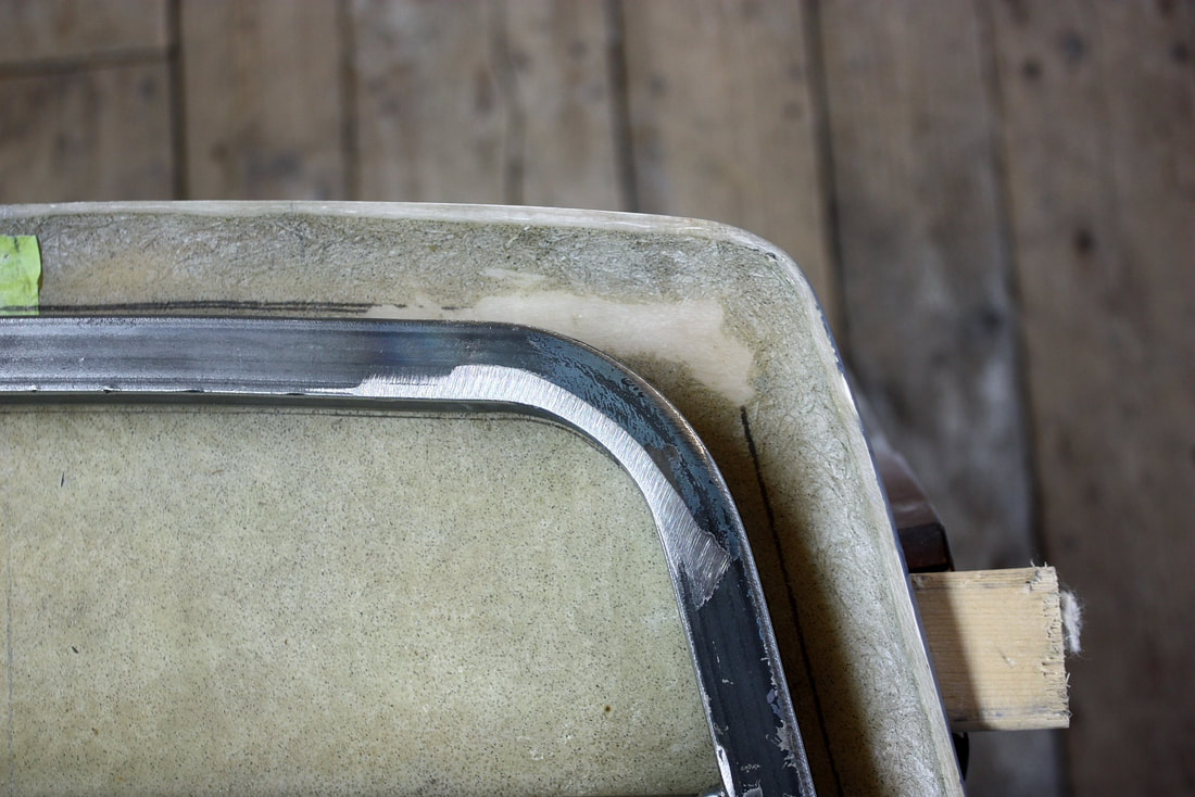
I bent the two front radii on separate pieces of tubing that were to be welded together, since it would have been nearly impossible to get the exact distance required between the two bends on a single piece. At least not without a CNC bender.
Once the two front bends were completed I moved on to making the compound curves in the tubing required to follow the arch of the deck lid skin. The perimeter frame is gently curved as viewed from the top as well as from this side view:
Making gentle curves were a lot more easily said than done. Even with the thin wall tubing I was using, it took a 48” lever arm welded to an old pipe bending die and all my strength to bend the tubing a tiny bit each time:
Making gentle curves were a lot more easily said than done. Even with the thin wall tubing I was using, it took a 48” lever arm welded to an old pipe bending die and all my strength to bend the tubing a tiny bit each time:
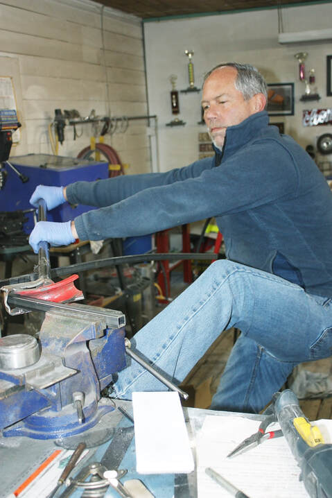
I used a series of little “pulls” every couple inches along the length of both legs, in both axes, to duplicate the curvature of the deck lid:
I used a series of little “pulls” every couple inches along the length of both legs, in both axes, to duplicate the curvature of the deck lid:
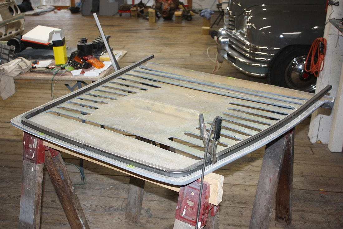
Shaping the frame to the underside of the deck lid worked as a “first-stage”, but the deck lid itself was warped, and quite flimsy so it was easily distorted just by having it upside down on a couple saw horses. In this next photo, I had clamped some steel bars to the lid in an attempt to prevent the panel from sagging too much due to its own weight. I was working on the second cross member near the front edge of the lid:
Shaping the frame to the underside of the deck lid worked as a “first-stage”, but the deck lid itself was warped, and quite flimsy so it was easily distorted just by having it upside down on a couple saw horses. In this next photo, I had clamped some steel bars to the lid in an attempt to prevent the panel from sagging too much due to its own weight. I was working on the second cross member near the front edge of the lid:
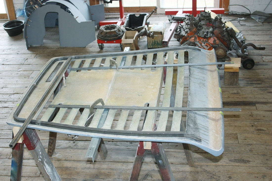
Once the rough shape of the perimeter frame was established, I welded the two halves of the frame together along with the front cross brace:
Once the rough shape of the perimeter frame was established, I welded the two halves of the frame together along with the front cross brace:
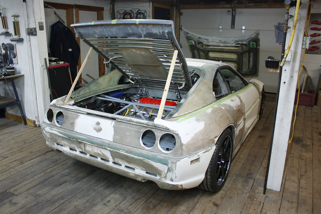
The next step required me to mock up the perimeter frame onto the chassis, clamp the deck lid skin to it, and check how well the lid followed the curvature of the surround. That would give me an idea how much more tweaking the perimeter frame would need.
So, I needed a means to support the frame on the chassis in the same position after each of the dozens of times I would remove it to adjust the curvature. At the front end I built a pair of mini fixed platforms attached to the hinge mounts:
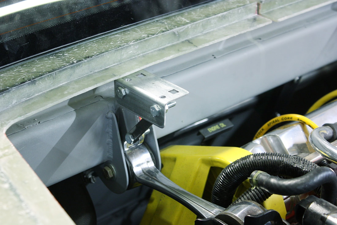
I could then rest the front of the frame on the supports without having to play around with my cool, but moveable hinges:
I could then rest the front of the frame on the supports without having to play around with my cool, but moveable hinges:
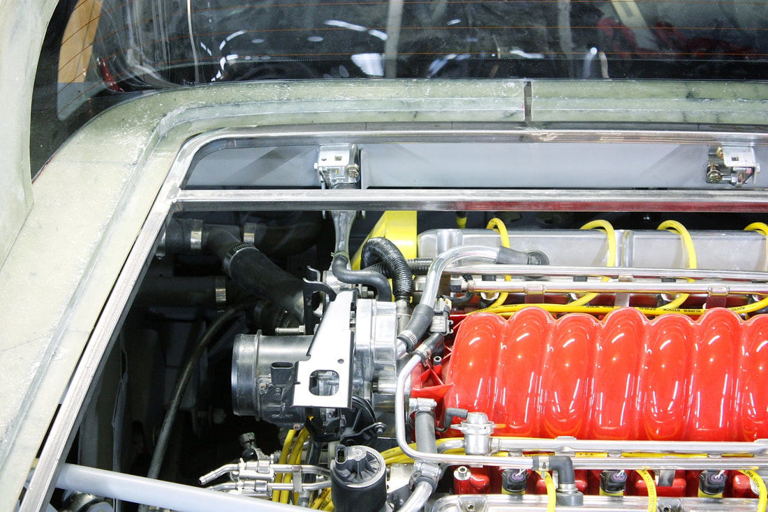
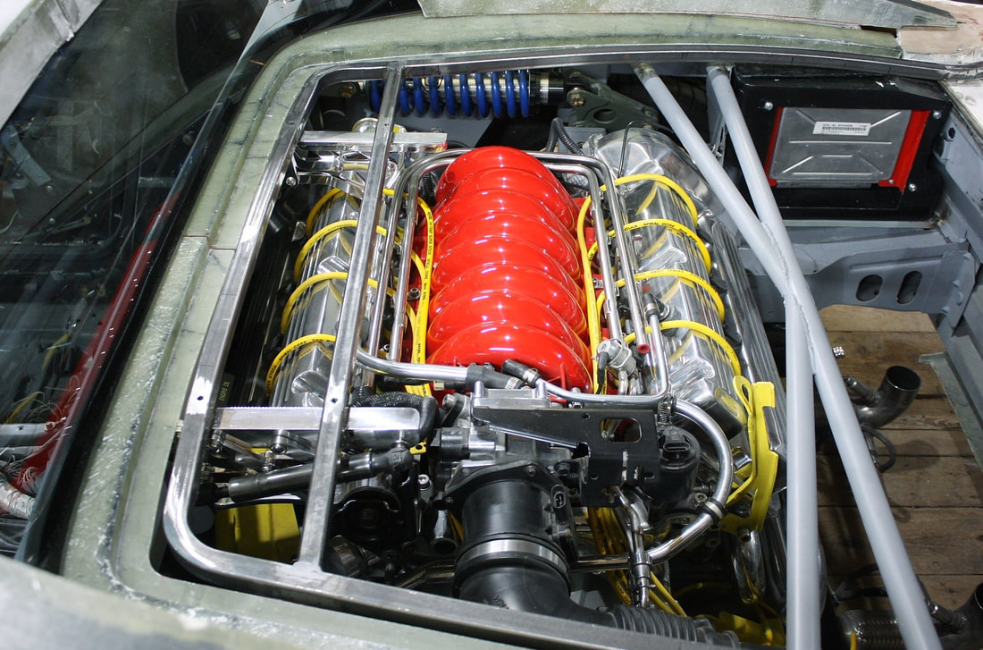
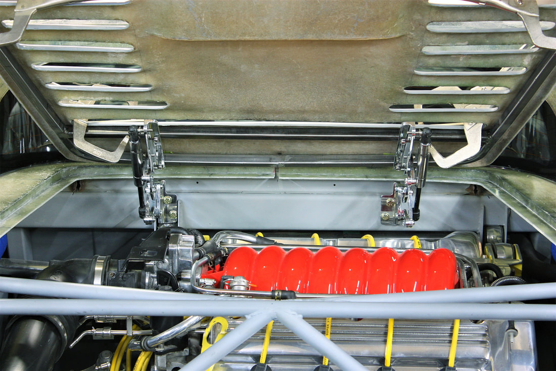
I supported the back edge of the framework at the right height by using stacks of magnets as support legs. If you squint, you can see the magnets between the frame and the ECM cooling box:
I supported the back edge of the framework at the right height by using stacks of magnets as support legs. If you squint, you can see the magnets between the frame and the ECM cooling box:
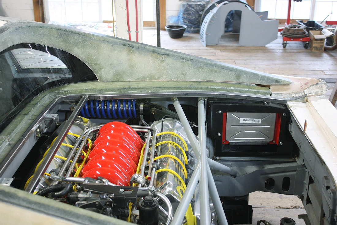
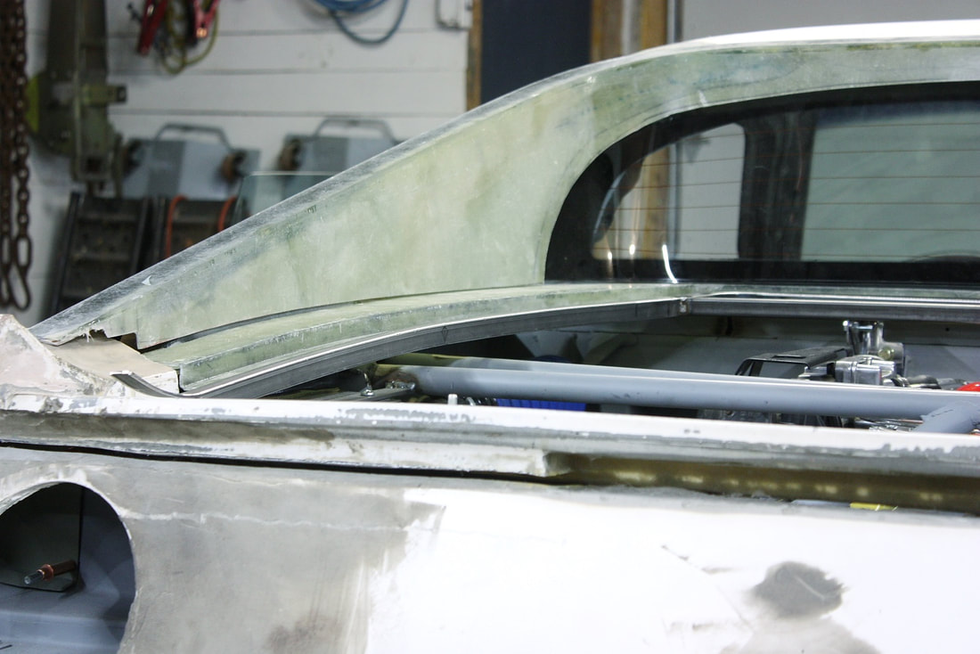
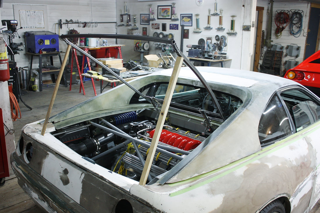
After the extremely tedious process of what amounted to bending a four legged, curved table to level it on an uneven floor, I finally found the sweet spot some 6 hours into it. This next photo shows the gentle curvature in the vertical axis that the side rails of the frame needed to follow:
After the extremely tedious process of what amounted to bending a four legged, curved table to level it on an uneven floor, I finally found the sweet spot some 6 hours into it. This next photo shows the gentle curvature in the vertical axis that the side rails of the frame needed to follow:
At this point I only had three sides of the frame made, with the rear-most cross member not yet done. This last leg would provide the mounting surface of the deck lid striker, and as such needed to be accurately curved to the deck lid and centered above the chassis where the latch would be installed.
That meant I needed to mock up the actual hinges, frame, and deck lid in their final positions to get the proper measurements. The first step was to accurately align the hinges on the chassis and to each other so that they wouldn’t fight each other when opened together via the frame:
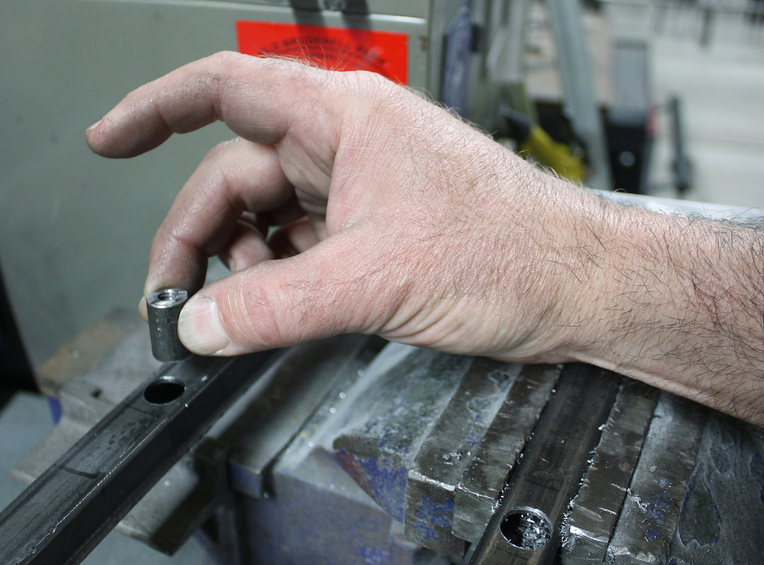
Next up was measuring the precise location of the four hinge mounting holes and transferring them to the perimeter frame. Then, I needed to figure out a way to solidly attach the perimeter frame to the hinges. The challenge was that by having chosen thin wall tubing, there wasn’t enough material to drill and tap the tube itself for fasteners. So I cut, drilled, and tapped some ½” diameter steel rod to make solid inserts like so:
Next up was measuring the precise location of the four hinge mounting holes and transferring them to the perimeter frame. Then, I needed to figure out a way to solidly attach the perimeter frame to the hinges. The challenge was that by having chosen thin wall tubing, there wasn’t enough material to drill and tap the tube itself for fasteners. So I cut, drilled, and tapped some ½” diameter steel rod to make solid inserts like so:
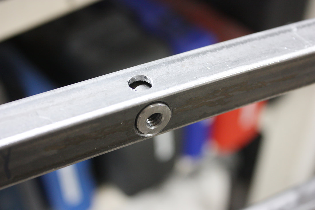
I chamfered the inserts and cross-drilled a hole through the tube in the opposite axis like this…:
I chamfered the inserts and cross-drilled a hole through the tube in the opposite axis like this…:
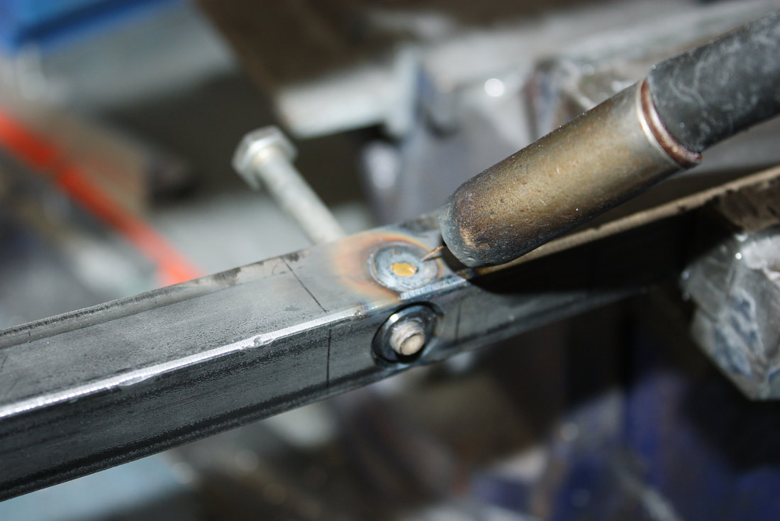
… and rosette welded the inserts from both the sides, and flush-welded the ends of the inserts to the top and bottom. I used a sacrificial bolt in the insert to keep slag from ruining the threads:
… and rosette welded the inserts from both the sides, and flush-welded the ends of the inserts to the top and bottom. I used a sacrificial bolt in the insert to keep slag from ruining the threads:
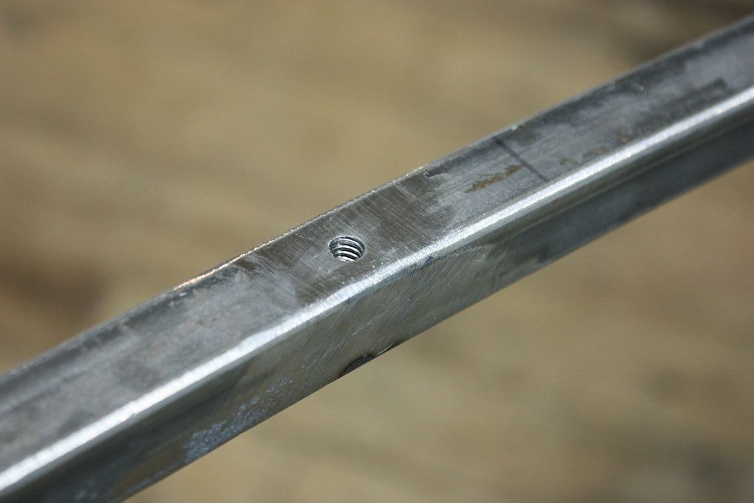
The final touch was grinding the welds even with the tube since these will be visible when the deck lid is open:
The final touch was grinding the welds even with the tube since these will be visible when the deck lid is open:
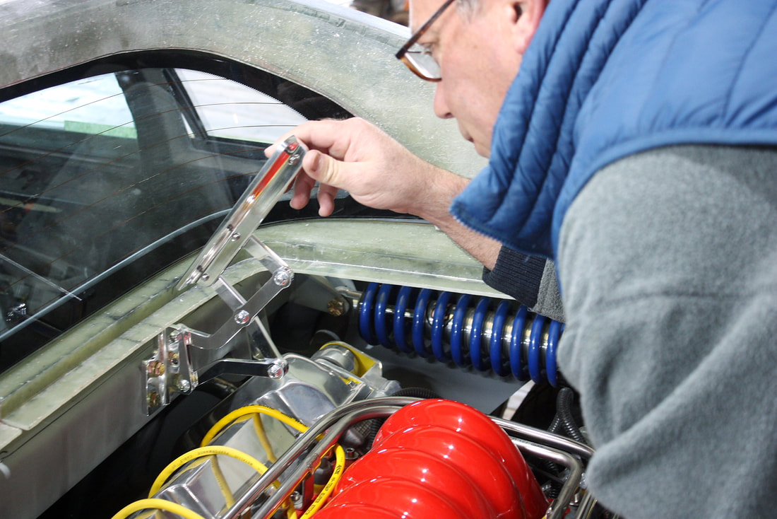
With that detail done, I bolted the perimeter frame to the hinges, and cycled the hinges through their range of motion to be certain they were well aligned and not binding:
With that detail done, I bolted the perimeter frame to the hinges, and cycled the hinges through their range of motion to be certain they were well aligned and not binding:
Then I clamped the deck lid skin to the frame, and cycled the lid several times to be certain it cleared the body work properly:
Then I clamped the deck lid skin to the frame, and cycled the lid several times to be certain it cleared the body work properly:
With everything working properly and aligned, I measured the location needed for the rear leg of the perimeter frame so it would line up with where I intended to mount the latch. That then allowed me to remove the deck lid once more, and form the rear cross member:
With everything working properly and aligned, I measured the location needed for the rear leg of the perimeter frame so it would line up with where I intended to mount the latch. That then allowed me to remove the deck lid once more, and form the rear cross member:
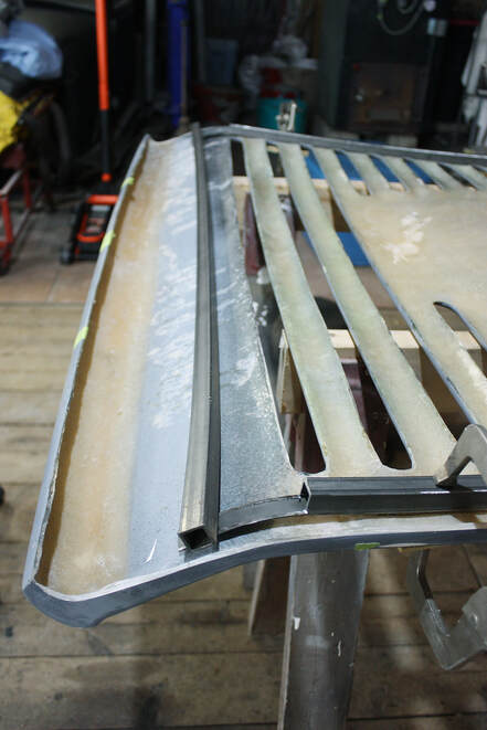
Once formed, I welded it to the perimeter frame and reinstalled it on the chassis to check for warpage from the welding heat:
Once formed, I welded it to the perimeter frame and reinstalled it on the chassis to check for warpage from the welding heat:
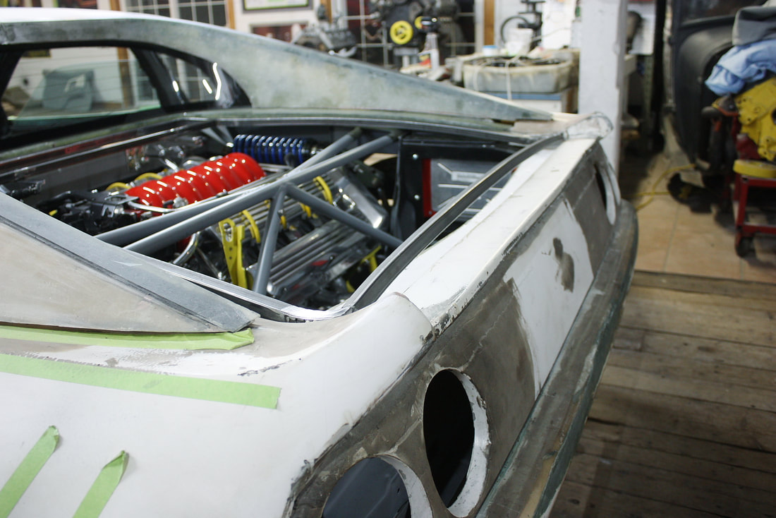
The last thing I concentrated on was the latch. On the Fiero, the striker is mounted to the chassis and the latch mechanism is bolted to the lid. This is opposite to the way the authentic Ferrari is set up, so I needed to make a few changes. The first was to remove the striker mounting pad from the inside of the trunk area:
The last thing I concentrated on was the latch. On the Fiero, the striker is mounted to the chassis and the latch mechanism is bolted to the lid. This is opposite to the way the authentic Ferrari is set up, so I needed to make a few changes. The first was to remove the striker mounting pad from the inside of the trunk area:
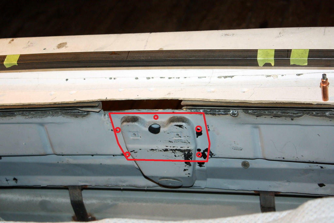
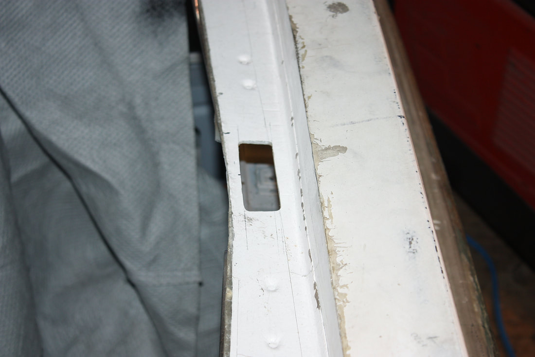
It’s a stamped steel boss, spot-welded to the rear trunk wall, forming a reinforced doubler. I simply drilled out the accessible spot welds and cut along the lower line to remove as much of it as possible.
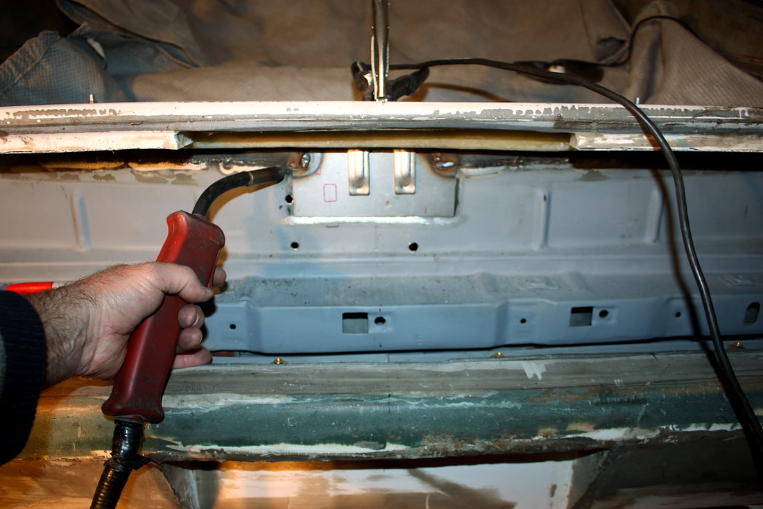
Next, I welded my own doubler to the outside trunk wall, tying it into the steel angles I had welded to the top of the trunk wall back in post #120:
It’s a stamped steel boss, spot-welded to the rear trunk wall, forming a reinforced doubler. I simply drilled out the accessible spot welds and cut along the lower line to remove as much of it as possible.
Next, I welded my own doubler to the outside trunk wall, tying it into the steel angles I had welded to the top of the trunk wall back in post #120:
The latch I used is instantly recognizable to anyone who’s ever fiddled with any GM car from the ‘70’s to the 90’s. It’s also the stock latch on the Fiero:
The latch I used is instantly recognizable to anyone who’s ever fiddled with any GM car from the ‘70’s to the 90’s. It’s also the stock latch on the Fiero:
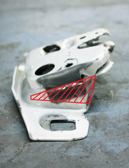
They’re simple, modular, and come ready to convert from direct manual release to remote manual release, to power release, to automatic pull down configurations. The only problem with them is I needed to get rid of the angle in the base plate:
They’re simple, modular, and come ready to convert from direct manual release to remote manual release, to power release, to automatic pull down configurations. The only problem with them is I needed to get rid of the angle in the base plate:
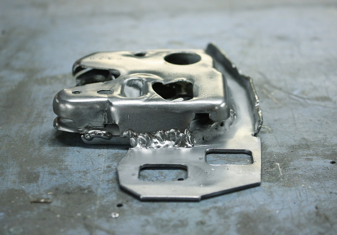
I took the latch apart, cut the base plate accordingly, then re-welded the assembly back together flat, like so:
I took the latch apart, cut the base plate accordingly, then re-welded the assembly back together flat, like so:
At that point I was ready to mock it up on my newly installed reinforcement plate so I could measure the cut-out needed in the fibreglass:
At that point I was ready to mock it up on my newly installed reinforcement plate so I could measure the cut-out needed in the fibreglass:
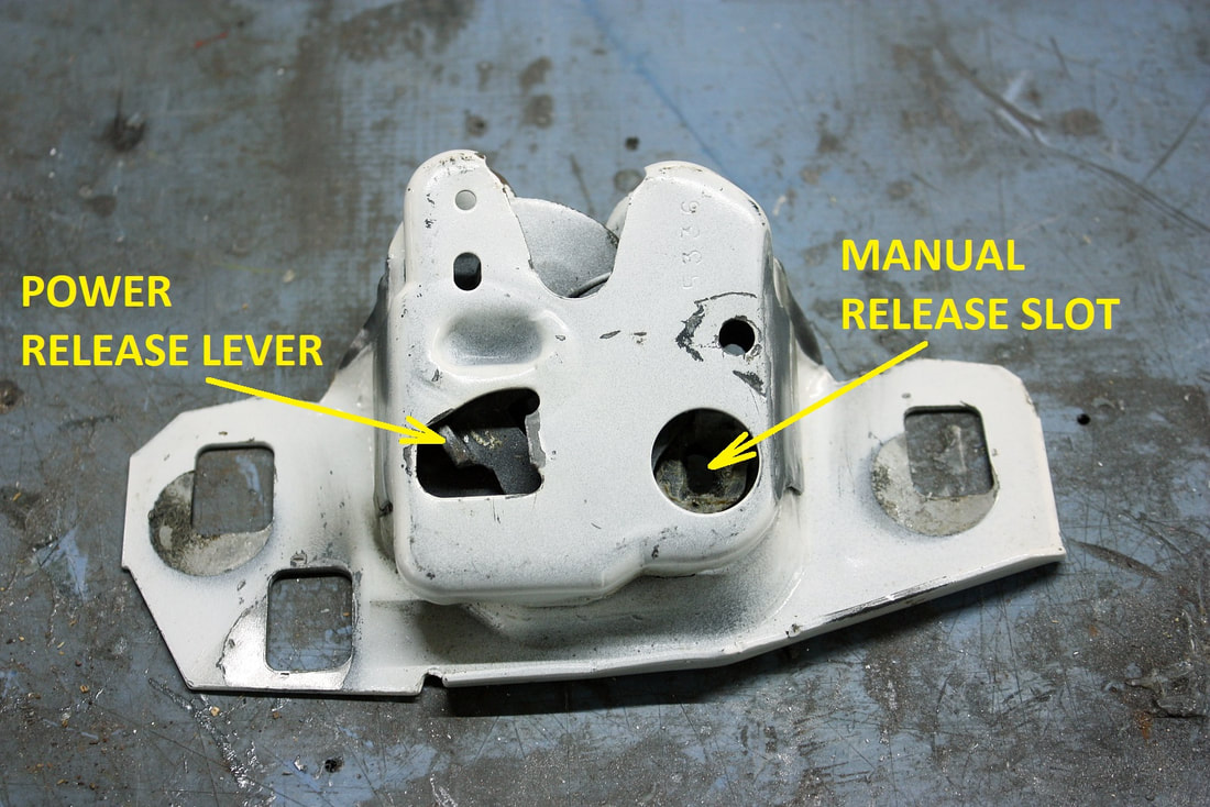
GM designed the latch with an integral manual key release slot accessible from either side of the assembly, maximizing the ability to mount the latch in any orientation, unless a power release solenoid was installed. In that case, the solenoid hid the manual release slot on that side. So to retain the ability to open the trunk manually with a key, the power solenoid had to be mounted on the inside of the trunk.
That initially presented a problem for me because I didn’t have room for the solenoid inside the engine bay due to the proximity of the exhaust system. But by mounting the latch with the solenoid outboard, I would have had no manual back up method to open the lid in case of a solenoid failure. My problem was solved when I discovered that GM also designed a power release solenoid with a remote, cable actuated manual release:
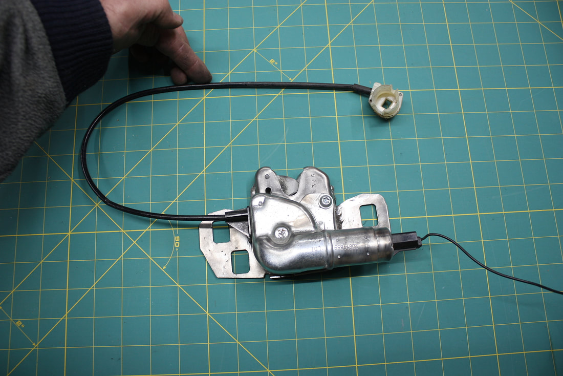
With this configuration, I could install the latch with the solenoid outside the engine bay, and still retain a manual release. I’ll most likely install the cable release behind the license plate, with a keyed cylinder:
With this configuration, I could install the latch with the solenoid outside the engine bay, and still retain a manual release. I’ll most likely install the cable release behind the license plate, with a keyed cylinder:
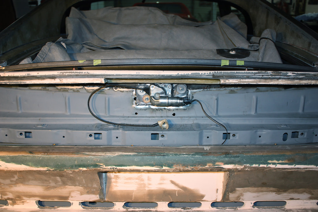
Here’s the only part that will be visible when the back end is complete:
Here’s the only part that will be visible when the back end is complete:
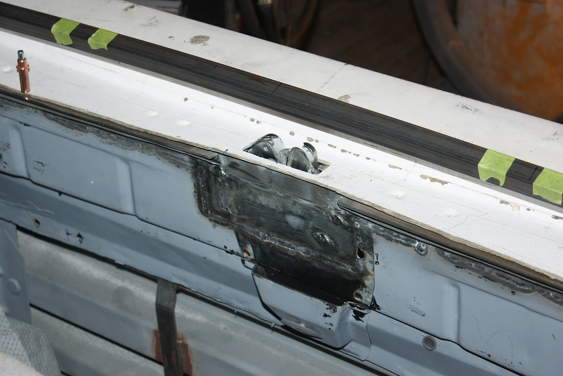
The last step was to fabricate a striker. Here, I simply bent some 8mm steel rod into a U shape that dropped down from the rear cross member of the deck lid frame. If it wasn’t clear why I needed to precisely locate the rear cross member of the deck lid frame earlier, it should make sense now:
The last step was to fabricate a striker. Here, I simply bent some 8mm steel rod into a U shape that dropped down from the rear cross member of the deck lid frame. If it wasn’t clear why I needed to precisely locate the rear cross member of the deck lid frame earlier, it should make sense now:
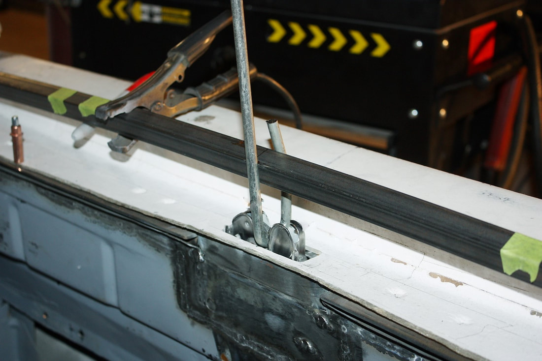
Once I was happy with the alignment of the striker, I tack welded it to the steel tube and trimmed off the excess:
Once I was happy with the alignment of the striker, I tack welded it to the steel tube and trimmed off the excess:
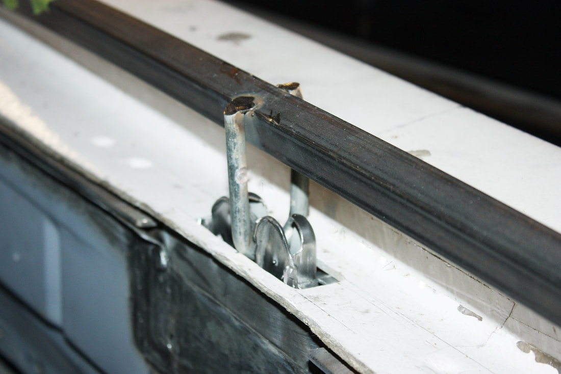
I’ll need a small gusset on the striker on the inboard side to close the gap, but otherwise I was ready to work on mounting the deck lid skin to the frame.
I’ll need a small gusset on the striker on the inboard side to close the gap, but otherwise I was ready to work on mounting the deck lid skin to the frame.

 RSS Feed
