In my last entry, I spaced the door hinges away from the door frames by 1 inch to move the pivot point further outboard. The door itself, nevertheless, had to remain in the stock location otherwise there would’ve been a 1 inch gap between the door and the chassis. This post is about the changes needed to the metal door structures to accommodate the relocated hinges.
This next pair of diagrams summarizes what I needed to do:
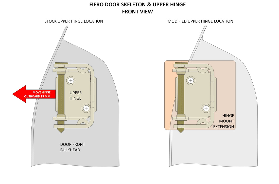
The drawings above are of metal door’s front bulkhead, looking aft. The left hand diagram shows where the hinge mounts to the door in the stock location, and the right hand image shows where the hinge needed to mount following the hinge’s relocation on the chassis. The peach-coloured square is a steel plate I planned to weld to the front bulkhead to stiffen the bulkhead and to give me more options should the hinge need to be moved even further outboard.
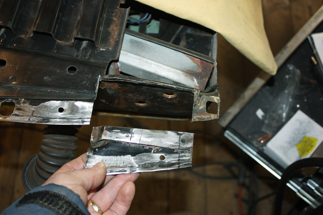
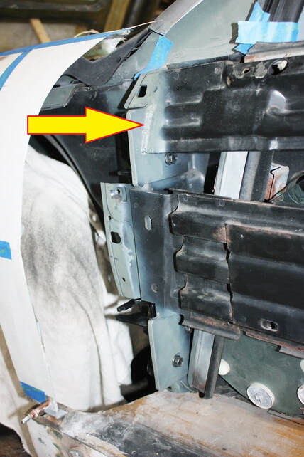
The hiccup with this plan is that the upper and lower hinges needed to protrude further outboard than the metal door skin allowed. To remedy this problem, the metal flange along the front edge of the door would have to be notched, like so:
The drawings above are of metal door’s front bulkhead, looking aft. The left hand diagram shows where the hinge mounts to the door in the stock location, and the right hand image shows where the hinge needed to mount following the hinge’s relocation on the chassis. The peach-coloured square is a steel plate I planned to weld to the front bulkhead to stiffen the bulkhead and to give me more options should the hinge need to be moved even further outboard.
The hiccup with this plan is that the upper and lower hinges needed to protrude further outboard than the metal door skin allowed. To remedy this problem, the metal flange along the front edge of the door would have to be notched, like so:
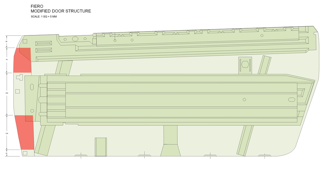
The cut-out in the lower hinge area isn’t structural… the sheet metal there simply provides a means to attach the Fiero plastic door skin. It’s a different story for the metal in the upper hinge area since the upper side impact beam attaches to it, but I found a work-around solution which I’ll cover later.
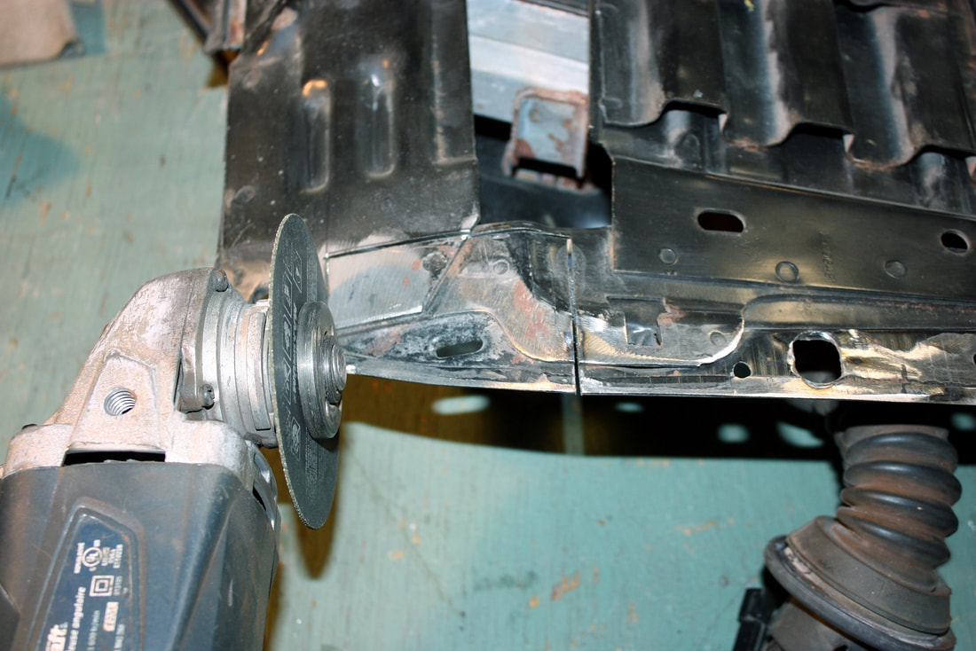
First, I lopped off the offending steel at the top of the door:
The cut-out in the lower hinge area isn’t structural… the sheet metal there simply provides a means to attach the Fiero plastic door skin. It’s a different story for the metal in the upper hinge area since the upper side impact beam attaches to it, but I found a work-around solution which I’ll cover later.
First, I lopped off the offending steel at the top of the door:
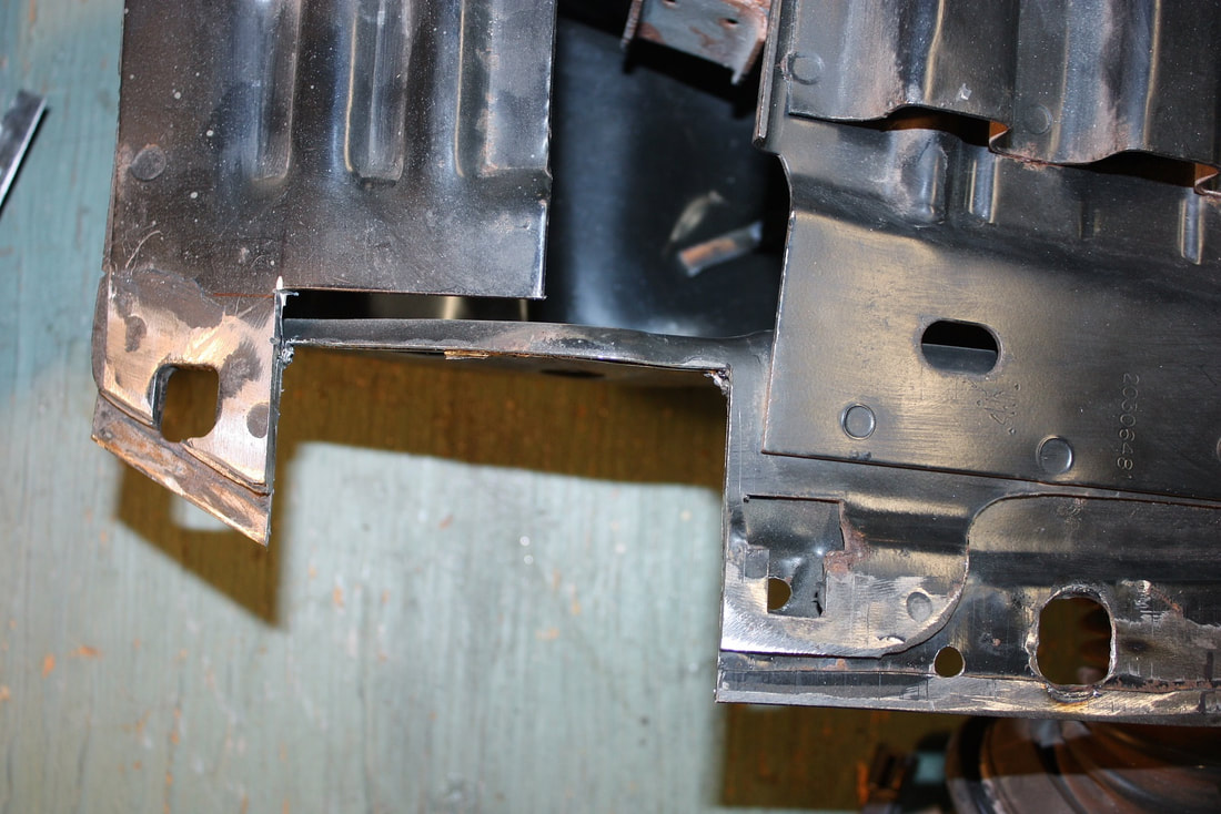
Then I test-fitted the upper hinge to make sure it would clear:
Then I test-fitted the upper hinge to make sure it would clear:
Then I did the same for the lower hinge:
Then I did the same for the lower hinge:
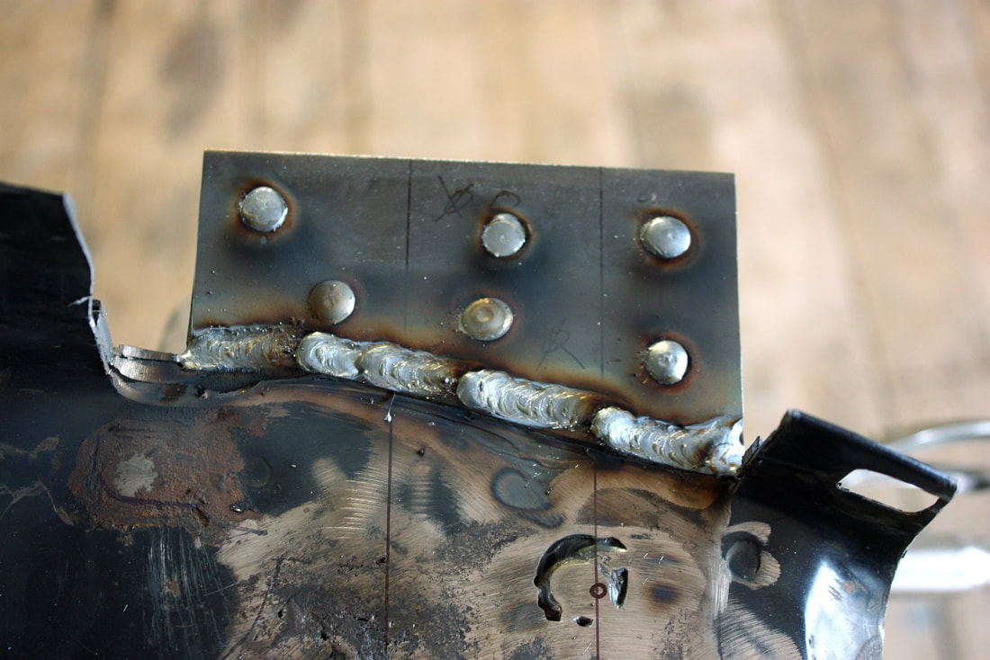
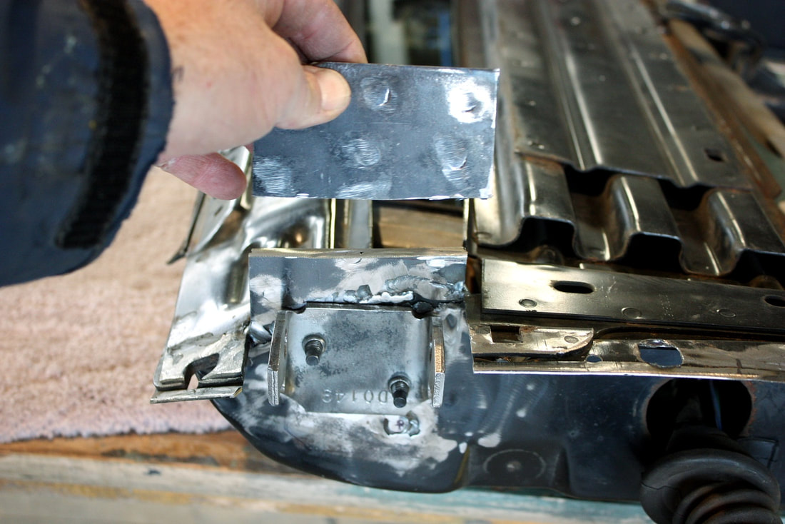
Next up was to measure, fabricate, and weld some 1/8” thick backing plates to the inside of the front bulkhead:
Next up was to measure, fabricate, and weld some 1/8” thick backing plates to the inside of the front bulkhead:
Then, to bring the backing plates level with the front of the bulkhead, I made and welded two shims bringing the total thickness of the new hinge mounting flange to a little over ¼” thick:
Then, to bring the backing plates level with the front of the bulkhead, I made and welded two shims bringing the total thickness of the new hinge mounting flange to a little over ¼” thick:
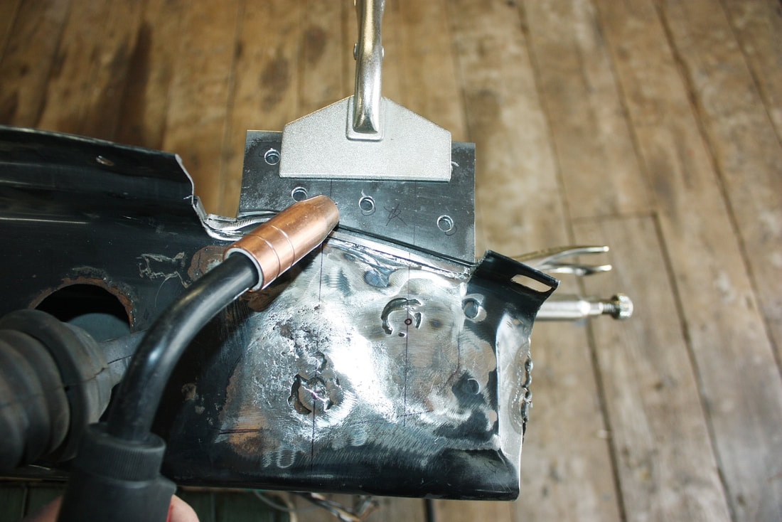
After the welds cooled, I ground them flush with the front face of the bulkhead giving a nice flat, sturdy mounting surface for the hinges.
The next step was to refit the door back into the chassis, using the masking tape I had placed earlier to make sure it was aligned the same as before I took it off the hinges:
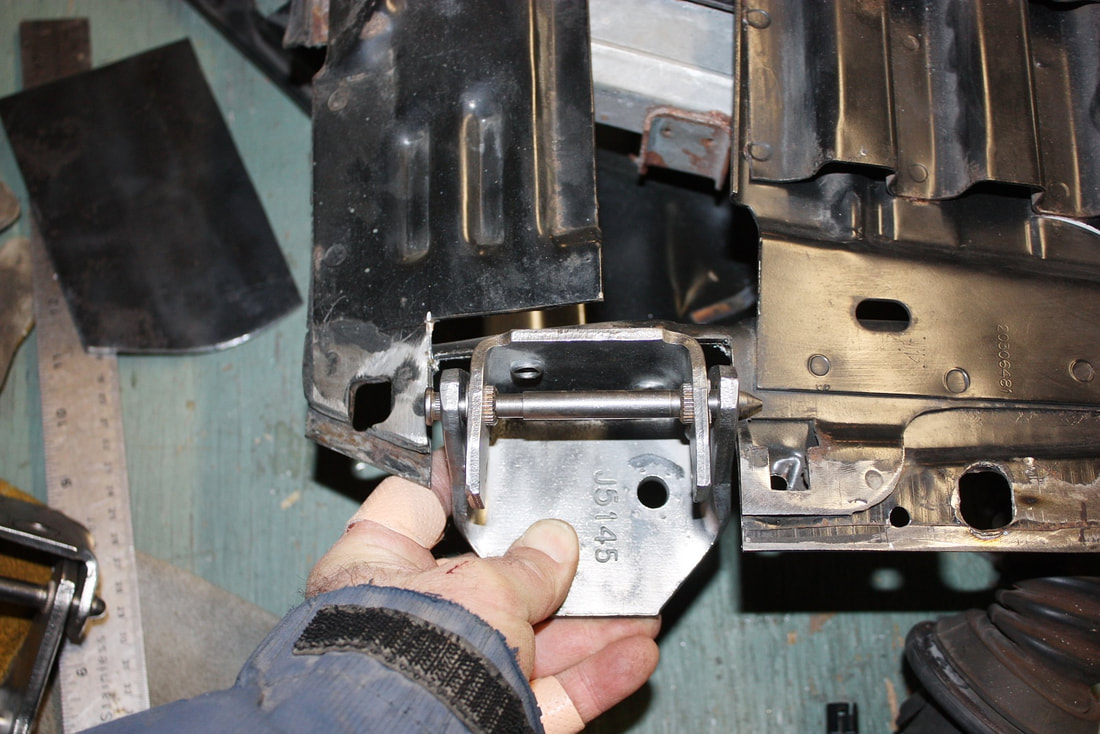
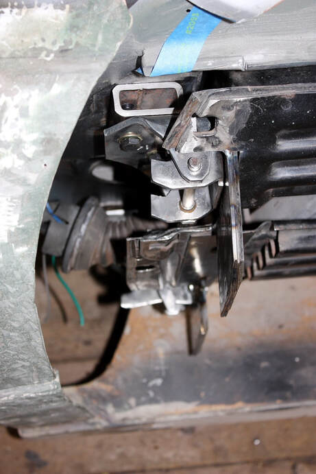
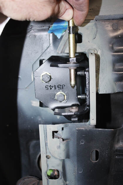
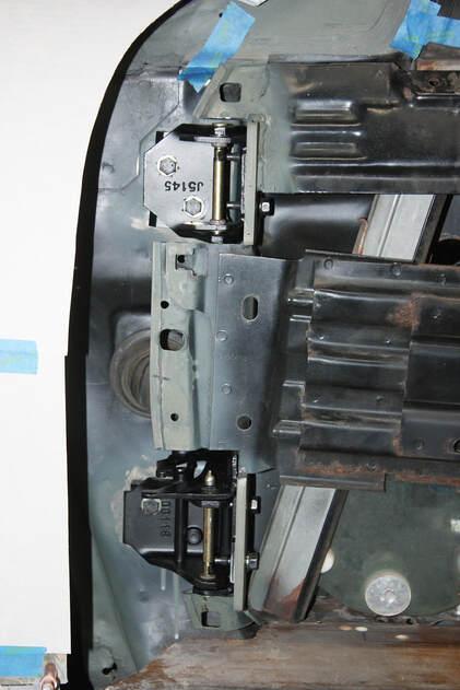
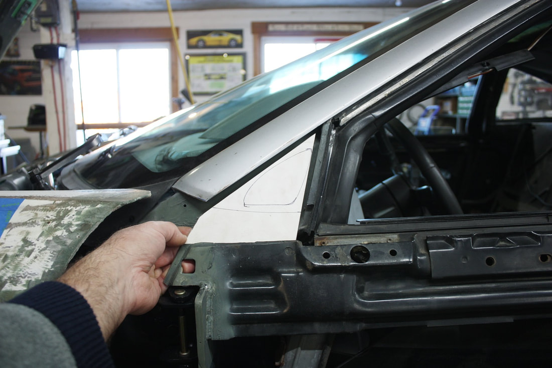
Once it was aligned and shimmed in place, I marked the location of the hinge mounting holes onto the new mounting flanges. This next photo shows everything in one shot… the top view of the chassis spacers, the relocated hinges, the extended hinge mounting flanges, and the cut-outs in the front skin-mounting flange:
Once it was aligned and shimmed in place, I marked the location of the hinge mounting holes onto the new mounting flanges. This next photo shows everything in one shot… the top view of the chassis spacers, the relocated hinges, the extended hinge mounting flanges, and the cut-outs in the front skin-mounting flange:
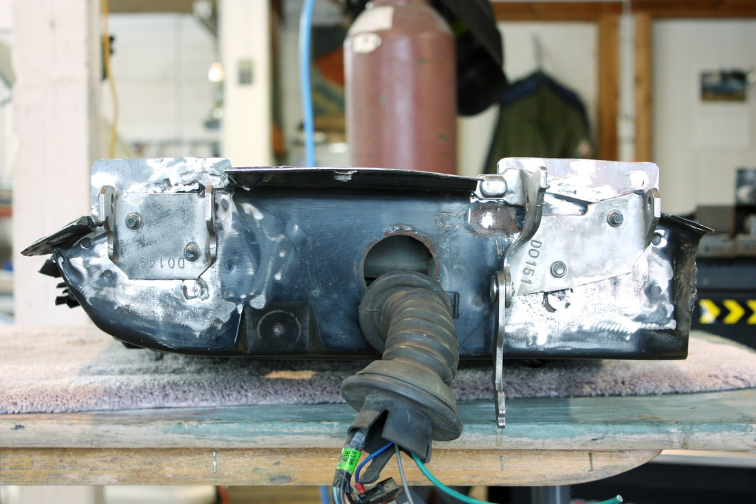
Here’s the rear view of the extended hinge mounting flanges before they were trimmed down to a reasonable length:
Here’s the rear view of the extended hinge mounting flanges before they were trimmed down to a reasonable length:
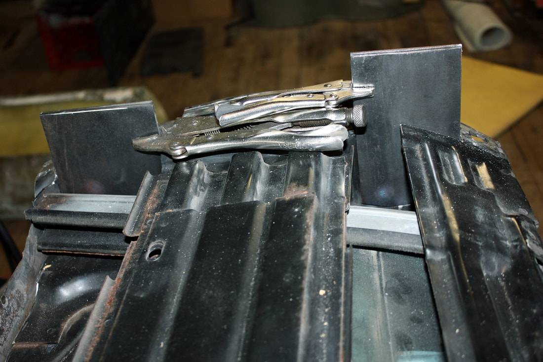
To drill the holes in the new hinge mounting flanges, I pulled the doors once again, drilled them, aligned the door-half of the hinges to each other with my long alignment pin, bolted the hinges on, and cut down the hinge mounting flanges. I purposely left enough room to be able to move the hinges a further inch outboard if required:
To drill the holes in the new hinge mounting flanges, I pulled the doors once again, drilled them, aligned the door-half of the hinges to each other with my long alignment pin, bolted the hinges on, and cut down the hinge mounting flanges. I purposely left enough room to be able to move the hinges a further inch outboard if required:
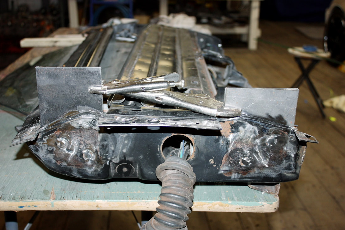
The doors were then reinstalled one last time using the new self-locking hinge pins rather than the single long rod I’d used for alignment purposes until this point:
The doors were then reinstalled one last time using the new self-locking hinge pins rather than the single long rod I’d used for alignment purposes until this point:
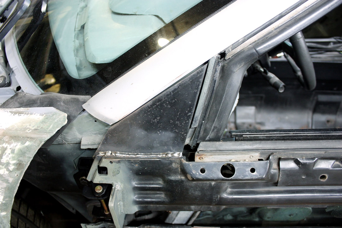
Earlier I mentioned I had a plan for re-securing the upper intrusion beam to the front bulkhead where I had notched it. That can be seen in this next photo where the beam has been re-welded to the upper hinge mounting plate, which itself is solidly welded to the front bulkhead as before:
Earlier I mentioned I had a plan for re-securing the upper intrusion beam to the front bulkhead where I had notched it. That can be seen in this next photo where the beam has been re-welded to the upper hinge mounting plate, which itself is solidly welded to the front bulkhead as before:
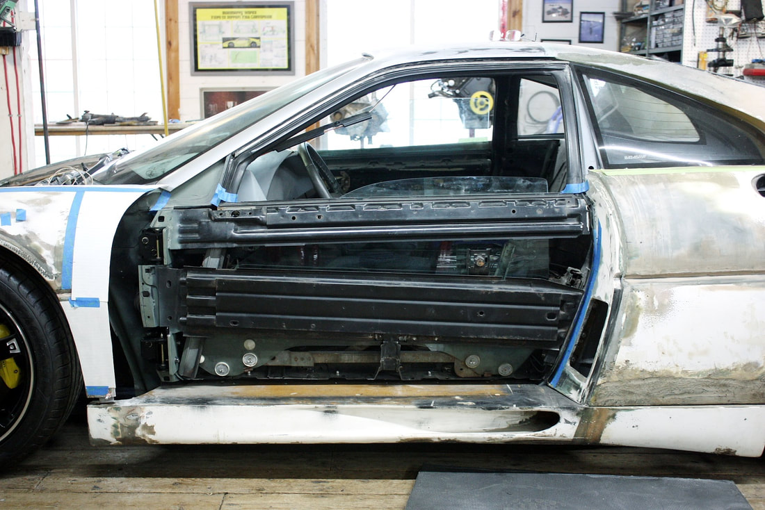
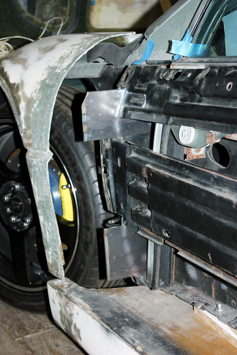
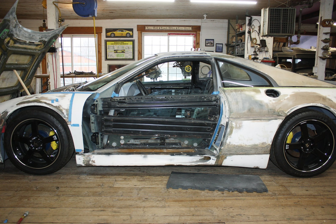
Stepping back a bit, here’s an overall view of the driver’s door reinstalled with the completed hinge mods:
Stepping back a bit, here’s an overall view of the driver’s door reinstalled with the completed hinge mods:
At this point I decided to take advantage of the fact the fibreglass skins weren’t yet reinstalled to make another important change to the steel structure: installing new mirror mounts. The Fiero mirrors are installed on mounts that are integral to the steel door structure, but they’re not in the right place for the F355:
At this point I decided to take advantage of the fact the fibreglass skins weren’t yet reinstalled to make another important change to the steel structure: installing new mirror mounts. The Fiero mirrors are installed on mounts that are integral to the steel door structure, but they’re not in the right place for the F355:
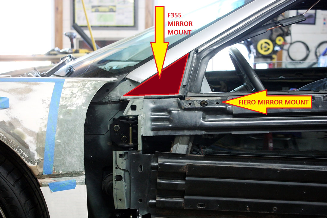
The F355’s mirrors are installed in the corner at the bottom of the A-pillar but they are attached to the door:
The F355’s mirrors are installed in the corner at the bottom of the A-pillar but they are attached to the door:

At last a simple modification! I made a cardboard template of the triangular area:
At last a simple modification! I made a cardboard template of the triangular area:
Then I cut and welded a 1/8” thick piece of sheet steel to the top of the metal door structure:
Then I cut and welded a 1/8” thick piece of sheet steel to the top of the metal door structure:
Once the welds cooled, I reinstalled the outer door skin:
Once the welds cooled, I reinstalled the outer door skin:

Next,, I mocked up the mirrors to make sure there was enough of the mount showing above the door skin to mount them:
Next,, I mocked up the mirrors to make sure there was enough of the mount showing above the door skin to mount them:
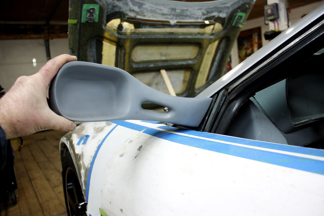
I won’t be installing the mirrors until after they’ve been modified to fold.
Finally, the proof of the pudding for the relocated hinges came when I checked to make sure the alignment hadn't changed:
I won’t be installing the mirrors until after they’ve been modified to fold.
Finally, the proof of the pudding for the relocated hinges came when I checked to make sure the alignment hadn't changed:
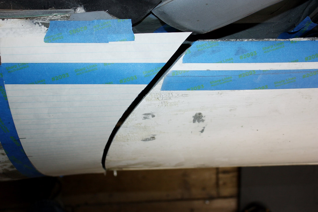
And second, that the action gave the desired result. When I opened the door, the flat surface along the top of the door skin neatly pulled away from the chassis rather trying to crash into its mating surface on top of the fender. Mission accomplished!:
And second, that the action gave the desired result. When I opened the door, the flat surface along the top of the door skin neatly pulled away from the chassis rather trying to crash into its mating surface on top of the fender. Mission accomplished!:
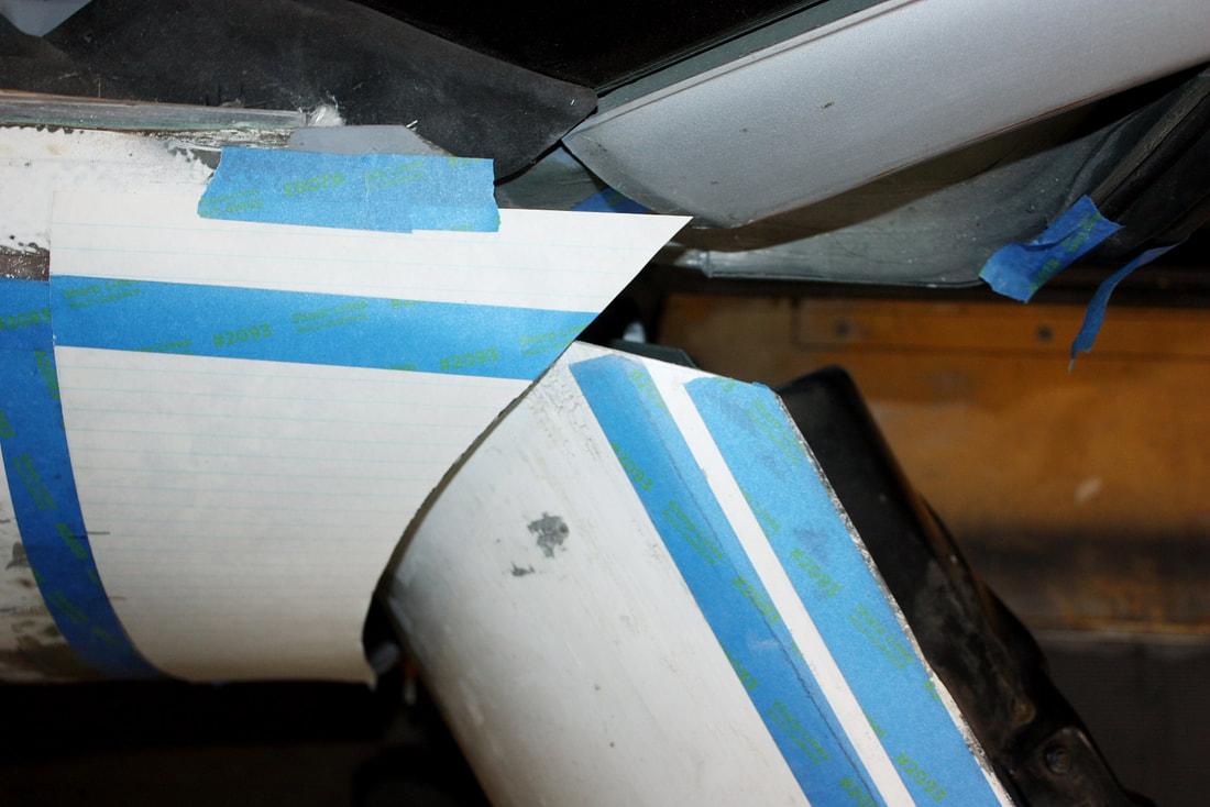
The location at which the door skin does tuck under the fender appears to be very close to rubbing the underside of the fender skin, but the paper template doesn’t follow the exact line it should because of the compound curves in that area. If I can’t prevent the door from interfering with the fender with one inch spacers under the hinges, I’ll just increase them to two inches.
The location at which the door skin does tuck under the fender appears to be very close to rubbing the underside of the fender skin, but the paper template doesn’t follow the exact line it should because of the compound curves in that area. If I can’t prevent the door from interfering with the fender with one inch spacers under the hinges, I’ll just increase them to two inches.

 RSS Feed
