Reshaping the rockers was next since, like the doors, the rockers are central to the alignment of the remaining panels. Working from the center of the car toward both ends minimizes the accumulation of misalignment errors.
The IFG rockers, having been originally integral with the door bottoms, were formed by cutting them off the doors, lower front fenders, and rear quarter bottoms, then rejoining the three pieces into a single piece between the wheel housings (Post #118). The previous owner intended to use these cobbled up rockers to make a set of molds and cast entirely new rockers from them. As such, a door sill was fabricated out of Medium Density Fiberboard (MDF) and bonded to the tops of the new rockers. He didn't complete the process before giving up on the project, so I inherited the bucks for the molds:
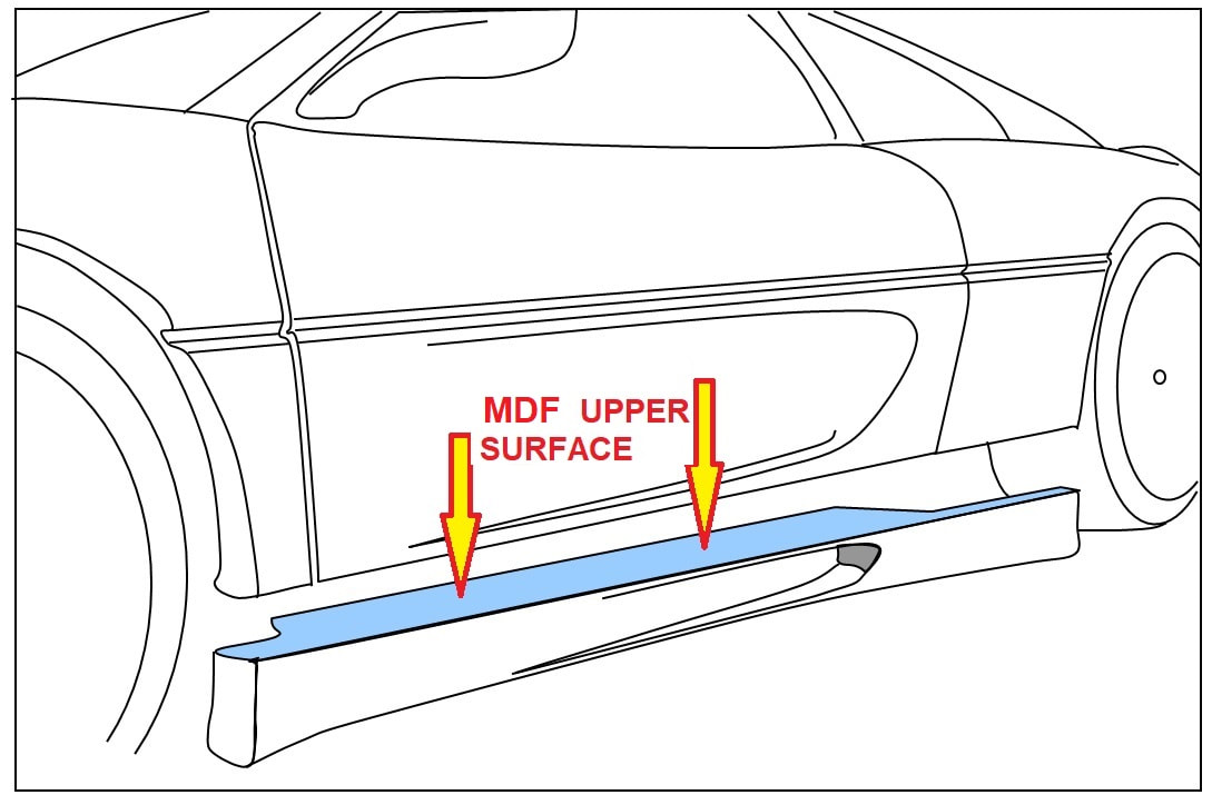
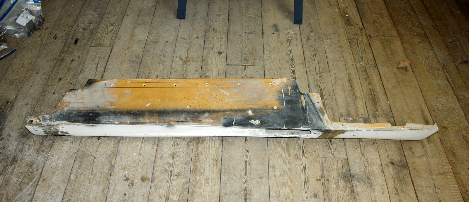
The MDF was fibreglassed in place from inside the rockers and left bare on the visible side. Here, the yellowish-brown is the natural colour, with black overspray from who-knows-what:
The MDF was fibreglassed in place from inside the rockers and left bare on the visible side. Here, the yellowish-brown is the natural colour, with black overspray from who-knows-what:
I decided to take a different tack. I believed the rockers could be restored with less work than creating new ones... but the MDF would have to be replaced.
The MDF door sills weren’t the only problems with the rockers. After measuring their lengths, the passenger rocker turned out to be 20mm longer than the driver’s side! That doesn’t sound like much, but rockers help define where the fender arches are located, so it would be quite noticeable if one wheel arch was nearly an inch off-centered from the wheel.
But how to decide whether the passenger rocker was too long or the driver’s too short? It wasn’t as easy as I thought it would be.
At first, I measured the distance from the center of the rear wheels to the rear edge of each rocker and found they were the same. So that narrowed the problem down to the front end of the rockers. To my surprise, the front end of the rockers were also the same distance from the center of the front wheels! How could that be?! Where did the extra 20mm disappear to?
Then I measured the wheelbase of the car on both sides and found the first problem:
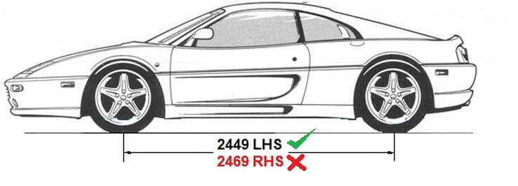
The wheelbase on the passenger side was 20mm longer than the driver’s side! All kinds of nightmare scenarios raced through my mind: could I have made that big of a mistake welding the suspension mounts? After a few moments of disbelief it dawned on me that I had never set the correct caster on the front suspension, and that caster affects the wheelbase. But could there really be that much adjustability?
To get a feel for just what sort of effect that caster could have on wheelbase, I dredged up and modified some of my front suspension drawings and came up with this:
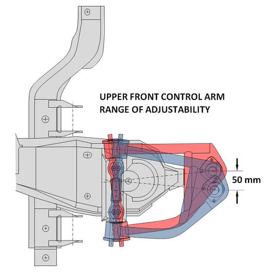
The red A-arm shows the position of least caster and longest wheelbase, while the blue arm is in the position of greatest caster and shortest wheelbase. These conditions are achievable by pivoting the upper A-arm cross shaft in the slotted mounting holes to opposite extremes resulting a whopping 50mm difference in wheelbase. This is a bit wider range than a stock Fiero due to my control arms being longer, acting as longer levers.
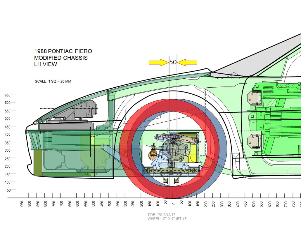
For another perspective, I drew the two extreme wheel positions to scale on my side view drawing of the chassis. It becomes really clear why it’s important to have an alignment done before reshaping the body of a car that is as badly made as this IFG kit. If, for example, I hadn’t checked the wheelbase, I could’ve easily attributed the misalignment of the passenger side wheel in the wheelhouse to the poorly made fenders. I could have then easily reshaped the entire fender to center the wheel properly in the fender arch, only to find after an alignment that the wheel was no longer centered. By as much as 2”!! That would’ve been an expensive lesson.
The red A-arm shows the position of least caster and longest wheelbase, while the blue arm is in the position of greatest caster and shortest wheelbase. These conditions are achievable by pivoting the upper A-arm cross shaft in the slotted mounting holes to opposite extremes resulting a whopping 50mm difference in wheelbase. This is a bit wider range than a stock Fiero due to my control arms being longer, acting as longer levers.
For another perspective, I drew the two extreme wheel positions to scale on my side view drawing of the chassis. It becomes really clear why it’s important to have an alignment done before reshaping the body of a car that is as badly made as this IFG kit. If, for example, I hadn’t checked the wheelbase, I could’ve easily attributed the misalignment of the passenger side wheel in the wheelhouse to the poorly made fenders. I could have then easily reshaped the entire fender to center the wheel properly in the fender arch, only to find after an alignment that the wheel was no longer centered. By as much as 2”!! That would’ve been an expensive lesson.
Correcting the problem seemed obvious enough: loosen the bolts on the upper A-arm cross shaft and push the wheel backwards until the correct wheelbase was achieved, and call it a day. Except it wasn’t that simple. Moving the cross shaft on the mounting bolts affects both caster and camber at the same time as shown in this excerpt from the ’88 service manual on page 3A-3:
Correcting the problem seemed obvious enough: loosen the bolts on the upper A-arm cross shaft and push the wheel backwards until the correct wheelbase was achieved, and call it a day. Except it wasn’t that simple. Moving the cross shaft on the mounting bolts affects both caster and camber at the same time as shown in this excerpt from the ’88 service manual on page 3A-3:
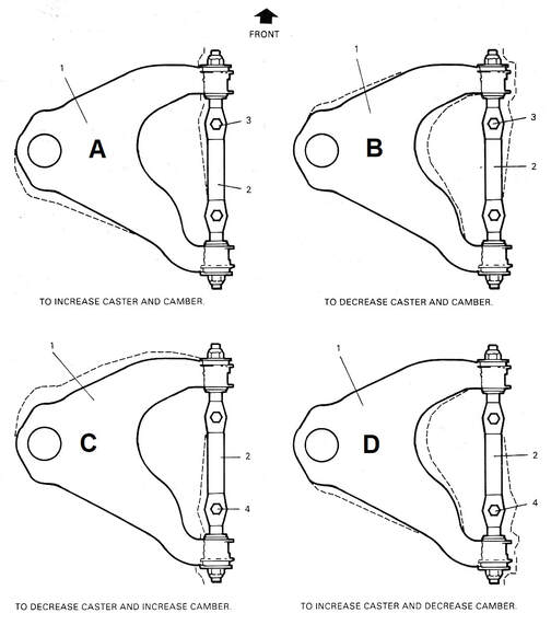
In the end, I loosened both cross shaft bolts and pulled outward on the leading edge of the A-arm (like figure A above) until the correct wheelbase was attained. This led to excessive camber, so my next step was to pull outward equally on both the leading and trailing arms to bring camber back into specs (not shown). This can’t be done easily with weight on wheels, so I jacked the front of the car up to make the adjustments a little at a time, then lowered it, jounced it, and re-measured, and repeated several times.
Finally with the wheelbase properly set at 2449 mm on both sides, I measured the distance between the centers of the front wheels to the leading edges of the two rocker panels mocked up on the car. The passenger side rocker was clearly too long. It didn’t take long to find out why:
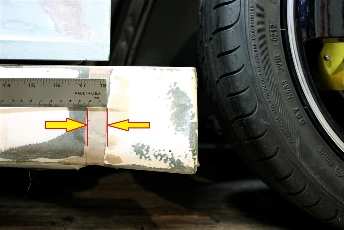
I found the extra 20 mm in the splice where the lower front fender portion of the rocker had been grafted to the door portion of the rocker. This was what I needed to know to make them the same.
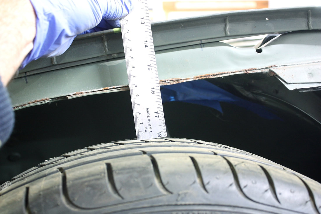
With that sorted out, I took the extra time to make sure the ground clearance was dialed in equally at all four corners by fine tuning the length of the adjustable coilovers. I also double checked to make sure I had equal and sufficient tire clearance to the underside of the upper frame rail. This extra step would assure that the wheels would have an even fender gap all the way around the openings:
I found the extra 20 mm in the splice where the lower front fender portion of the rocker had been grafted to the door portion of the rocker. This was what I needed to know to make them the same.
With that sorted out, I took the extra time to make sure the ground clearance was dialed in equally at all four corners by fine tuning the length of the adjustable coilovers. I also double checked to make sure I had equal and sufficient tire clearance to the underside of the upper frame rail. This extra step would assure that the wheels would have an even fender gap all the way around the openings:
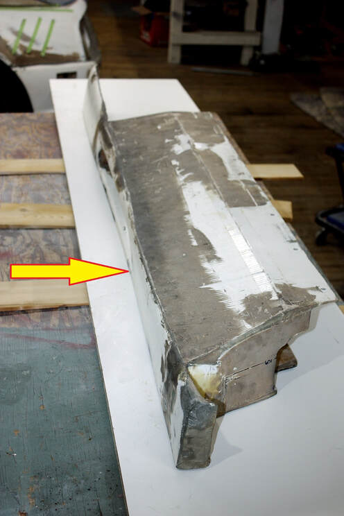
Next I started documenting the rest of the modifications I’d have to make to the rockers to straighten them. In the photo below it’s quite obvious how the rocker followed the coke-bottle shape of the original doors: bowing about a ½” inward, mid-length:
Next I started documenting the rest of the modifications I’d have to make to the rockers to straighten them. In the photo below it’s quite obvious how the rocker followed the coke-bottle shape of the original doors: bowing about a ½” inward, mid-length:
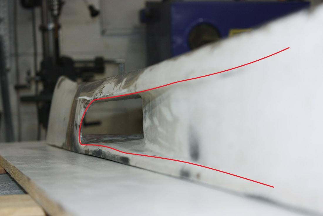
Also from the above photo it’s clear the small rocker scoop is terribly misshaped. There were bows and wows and dips in the “floor” and “ceiling” along the entire length of the scoops, and the mouth of the scoop didn’t come close to matching the lines of the larger door scoop above it.
Here’s another view of the bowing coke-bottle shape, with the rocker upside down on a piece of melamine particle board:
And here’s a close-up view of the crazy lumps and bumps in the ramps leading up to the scoop mouth on the driver’s side rocker (both were about the same condition):
And here’s a close-up view of the crazy lumps and bumps in the ramps leading up to the scoop mouth on the driver’s side rocker (both were about the same condition):
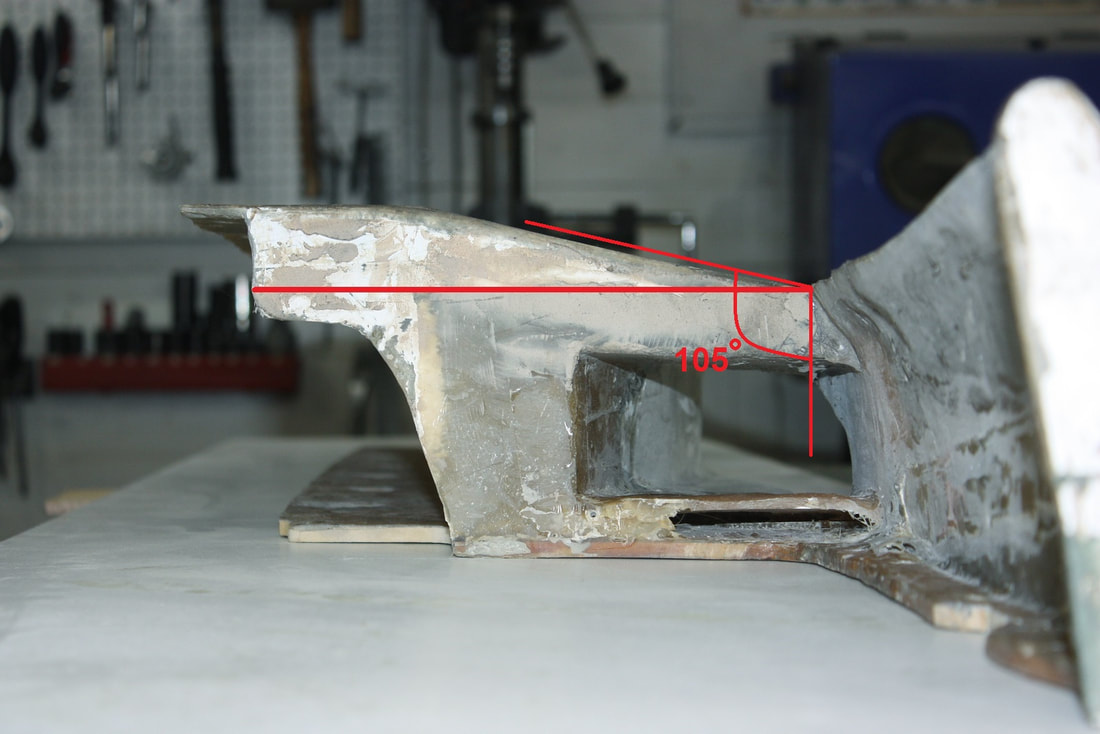
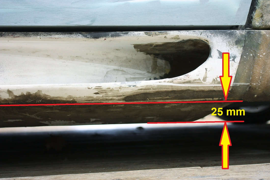
As I looked more closely at the rockers, I realized that they were the lowest hanging portion of the entire chassis, which unnecessarily reduced my ground clearance. The previous owner had modified them to account for the extra thickness of frame stiffening channels welded to the frame after he chopped the top of his car. So the rockers, rather than turning 90 degrees inboard along the bottom edge, sloped gently downward at about 105 degrees first, before levelling off horizontal to the ground. Here’s the end view of a rocker (that’s upside down) demonstrating the point:
As I looked more closely at the rockers, I realized that they were the lowest hanging portion of the entire chassis, which unnecessarily reduced my ground clearance. The previous owner had modified them to account for the extra thickness of frame stiffening channels welded to the frame after he chopped the top of his car. So the rockers, rather than turning 90 degrees inboard along the bottom edge, sloped gently downward at about 105 degrees first, before levelling off horizontal to the ground. Here’s the end view of a rocker (that’s upside down) demonstrating the point:
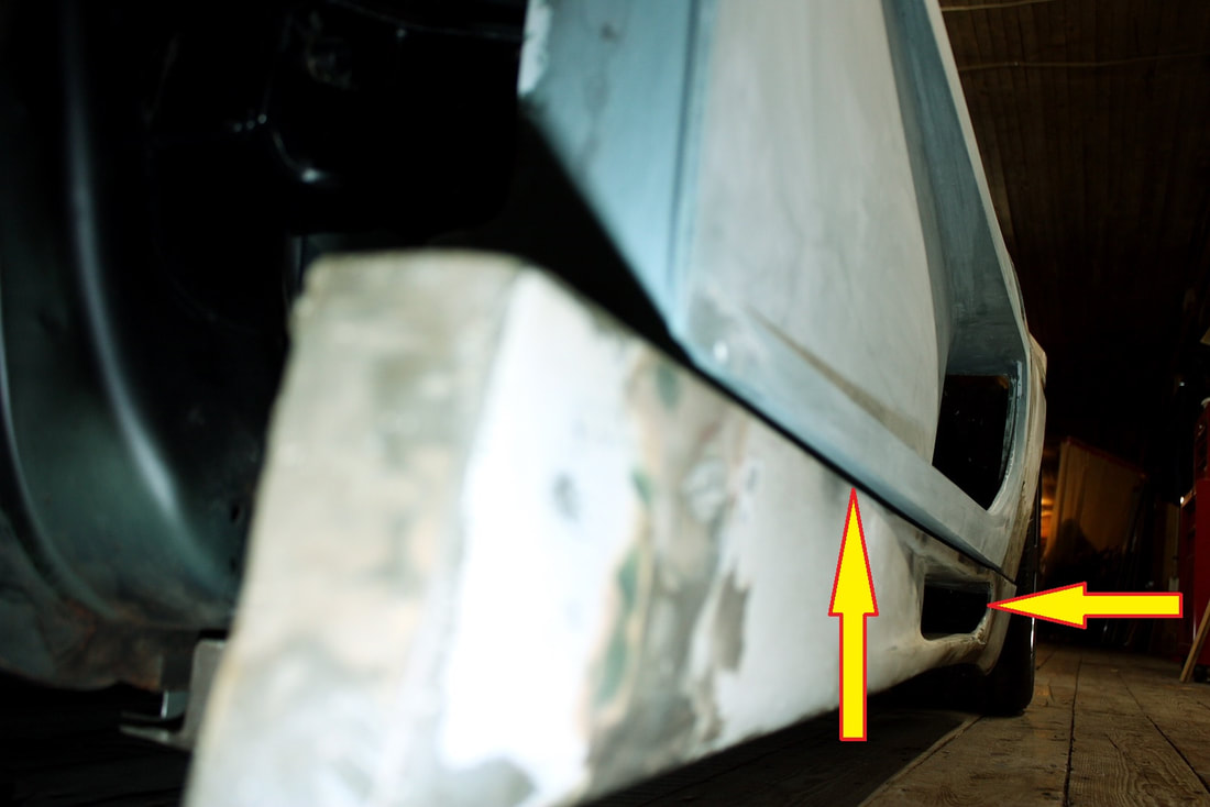
When installed on the car, that extra down-slope resulted in a decrease in ground clearance by 25 mm:
When installed on the car, that extra down-slope resulted in a decrease in ground clearance by 25 mm:
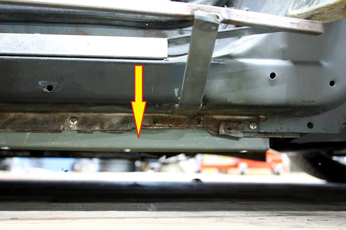
In fact, during the “mounting phase” of the body panels, I somewhat mindlessly fabbed up an extension to the stock weld flange along the bottom of the metal rockers to accommodate the low hanging fibreglass panel, shown here:
In fact, during the “mounting phase” of the body panels, I somewhat mindlessly fabbed up an extension to the stock weld flange along the bottom of the metal rockers to accommodate the low hanging fibreglass panel, shown here:
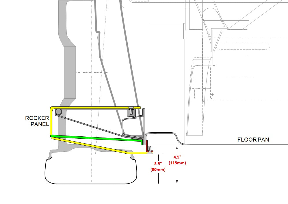
My car is a hard top though, so it's structurally rigid without the added stiffening channels that these rockers were made to conceal. Given all the other modifications needed to the rockers, I decided it would be worth straightening their bottoms, like the green line in the drawing below, and removing the flange extensions I had created (red bracket):
My car is a hard top though, so it's structurally rigid without the added stiffening channels that these rockers were made to conceal. Given all the other modifications needed to the rockers, I decided it would be worth straightening their bottoms, like the green line in the drawing below, and removing the flange extensions I had created (red bracket):
At this point I was confident I had mapped out all the rocker panel deficiencies and that I could start getting my hands dirty again.
At this point I was confident I had mapped out all the rocker panel deficiencies and that I could start getting my hands dirty again.

 RSS Feed
