It was a long tough slog getting the driver’s side rear quarter panel up to snuff, so it was a welcome relief to work on a couple of close-in details rather than the large expanse of the panel itself.
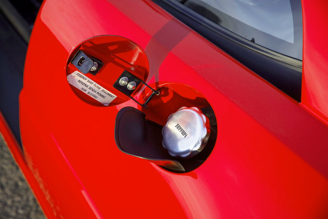
One detail was the fuel filler port. The authentic Ferrari F355 has the door just under the quarter window and from the photo below it opens forward, much like the Fiero filler door:
It was a long tough slog getting the driver’s side rear quarter panel up to snuff, so it was a welcome relief to work on a couple of close-in details rather than the large expanse of the panel itself.
One detail was the fuel filler port. The authentic Ferrari F355 has the door just under the quarter window and from the photo below it opens forward, much like the Fiero filler door:
The IFG kit had a simple embossed line on the quarter panel showing where to make the hole, and presumably the cut-out piece was to be used as the door. Neither of the two kits I had came with a custom pocket or hinge system so I assume the builder was left to his own imagination for these details.
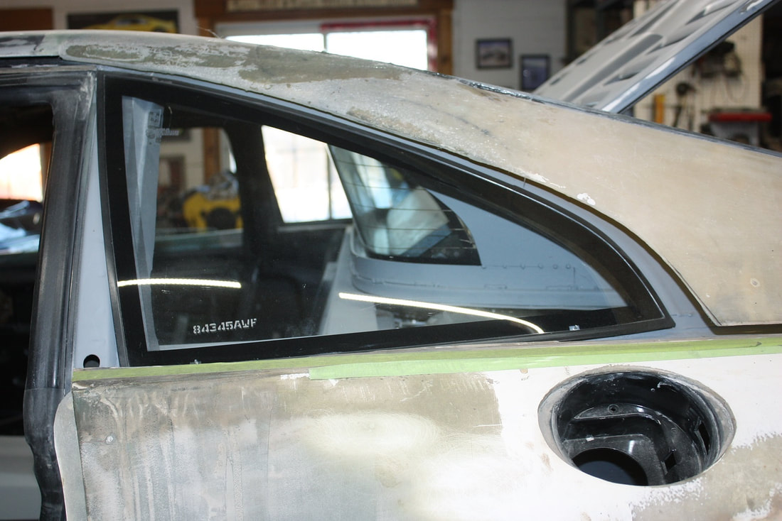
On a simple Fiero re-body, mounting the filler door would’ve had its own set of challenges because (as I learned) there was no way to re-use the Fiero hinge… the geometry of a hinge made for a round door isn’t the same as one for an oval door. I also had the added challenge of a stretched chassis and a radiator in the way of the fuel filler port. But I was determined to find a way to make it all work rather than relocate the filler pocket that Don (previous owner) had cut and glassed into place:
The IFG kit had a simple embossed line on the quarter panel showing where to make the hole, and presumably the cut-out piece was to be used as the door. Neither of the two kits I had came with a custom pocket or hinge system so I assume the builder was left to his own imagination for these details.
On a simple Fiero re-body, mounting the filler door would’ve had its own set of challenges because (as I learned) there was no way to re-use the Fiero hinge… the geometry of a hinge made for a round door isn’t the same as one for an oval door. I also had the added challenge of a stretched chassis and a radiator in the way of the fuel filler port. But I was determined to find a way to make it all work rather than relocate the filler pocket that Don (previous owner) had cut and glassed into place:
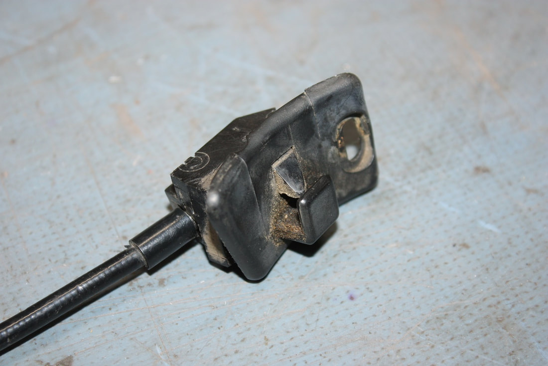
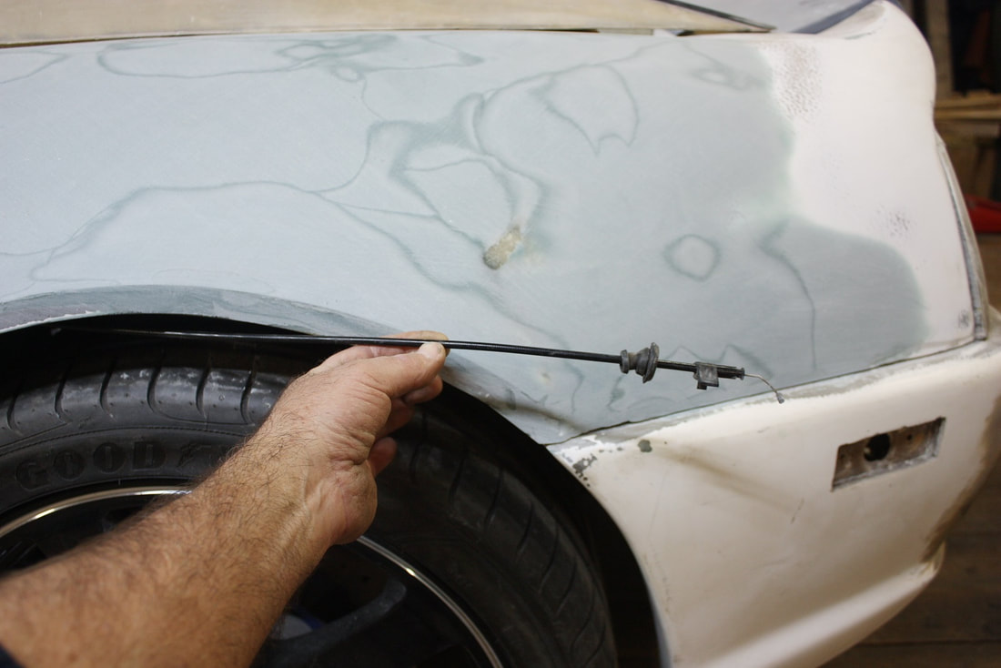
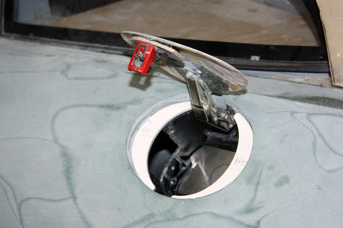
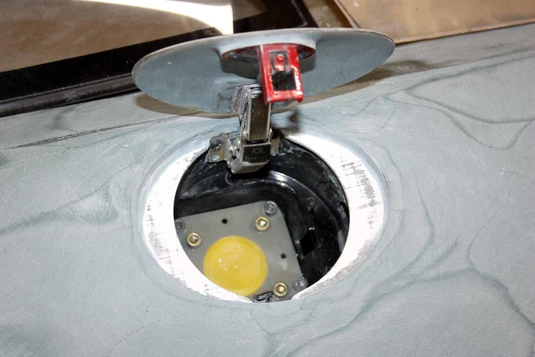
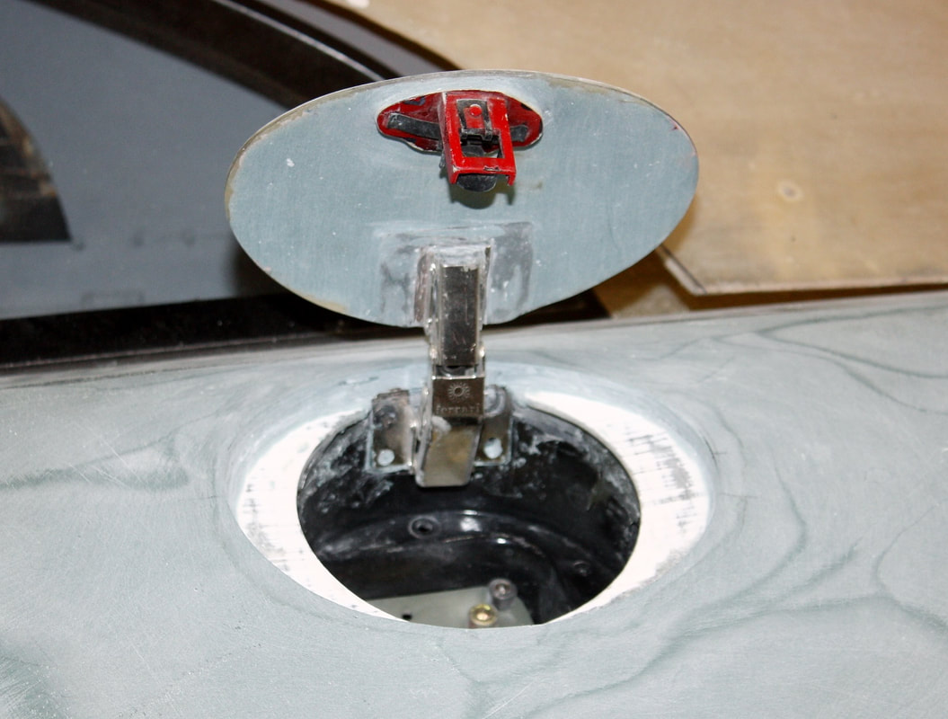
The first challenge I dealt with was finding a suitable door release mechanism. I thought about a simple magnetic push-to-release/latch cabinet-style mechanism, but that would’ve precluded a remote release. So I revisited the stock Fiero release latch and cable:
The first challenge I dealt with was finding a suitable door release mechanism. I thought about a simple magnetic push-to-release/latch cabinet-style mechanism, but that would’ve precluded a remote release. So I revisited the stock Fiero release latch and cable:
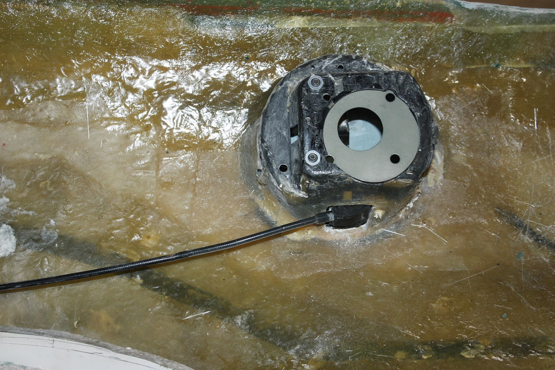
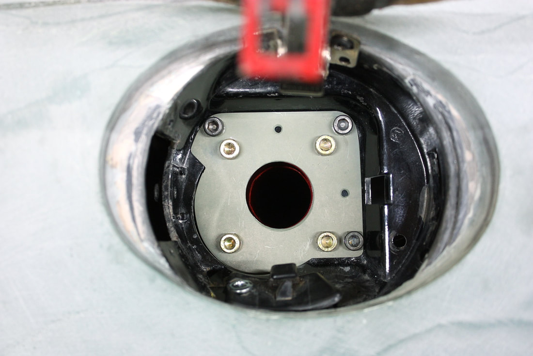
Because of the 3” chassis stretch, the cable wasn’t going to be long enough to reach the cabin. I figured I’d solve that problem by using a remote electrically actuated solenoid to pull the cable. That also freed up my ability to mount the latch and cable in any orientation within the pocket. So I cut a new hole in the plastic pocket and mounted the latch and cable at the bottom of the pocket like so:
Because of the 3” chassis stretch, the cable wasn’t going to be long enough to reach the cabin. I figured I’d solve that problem by using a remote electrically actuated solenoid to pull the cable. That also freed up my ability to mount the latch and cable in any orientation within the pocket. So I cut a new hole in the plastic pocket and mounted the latch and cable at the bottom of the pocket like so:
I led the cable backwards to the area above the rear wheel, and clamped it to the upper frame rail above the wheel well liner:
I led the cable backwards to the area above the rear wheel, and clamped it to the upper frame rail above the wheel well liner:
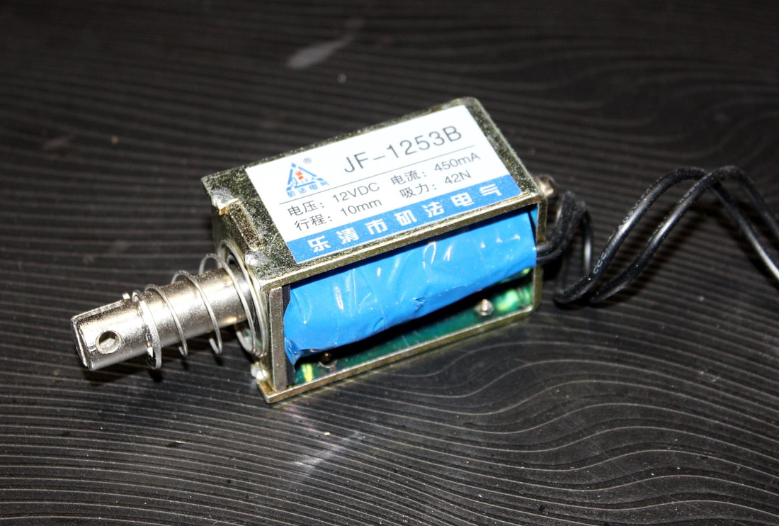
That gave me the space to mount a solenoid onto the frame rail to pull the cable remotely with the push of a button. I’d also have access to the cable from inside the engine bay if ever the solenoid failed. So I ordered a 12 volt, 0.5 amp solenoid with a 10mm throw and a 42N (9.5 lb) pull force:
That gave me the space to mount a solenoid onto the frame rail to pull the cable remotely with the push of a button. I’d also have access to the cable from inside the engine bay if ever the solenoid failed. So I ordered a 12 volt, 0.5 amp solenoid with a 10mm throw and a 42N (9.5 lb) pull force:
I’ll show how I connected it later in a section covering the electrical work.
If you didn’t catch it earlier when I mounted the latch at the bottom of the pocket, you’ll understand why I didn’t install the latch in the stock location when you check out this next photo:
I’ll show how I connected it later in a section covering the electrical work.
If you didn’t catch it earlier when I mounted the latch at the bottom of the pocket, you’ll understand why I didn’t install the latch in the stock location when you check out this next photo:
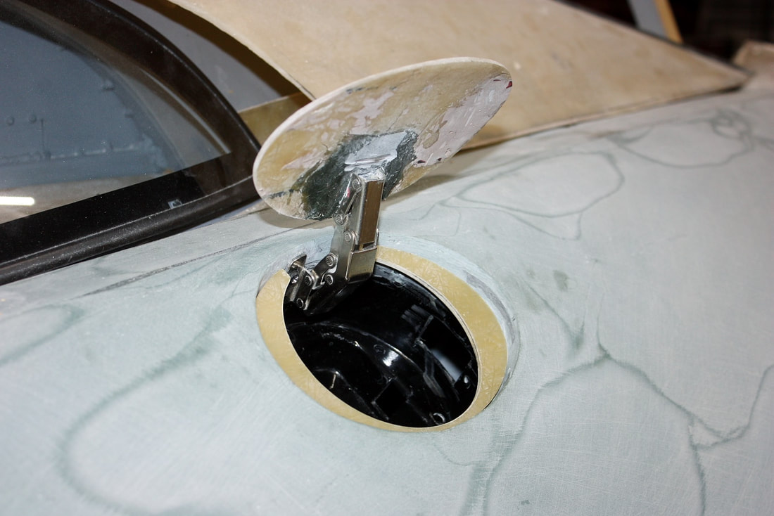
As I’ve mentioned a couple times in this blog, I wanted to add a few personal touches to the car that weren’t in keeping with the authentic F355. While playing around with all sorts of filler door hinging ideas, I fell in love with a simple change: an upward rather than a forward opening door.
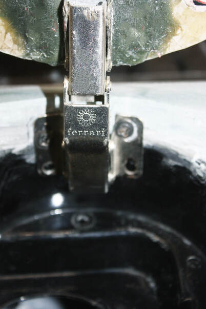
There were functional and cosmetic reasons for this choice. As I mentioned earlier, the simple stock Fiero hinge couldn’t be used since the door needed a compound motion that the stock hinge couldn’t provide. I found a 6 bar, compound motion cabinet hinge that pulled the door away from the quarter panel while swinging it open. It worked best by installing the hinge on the door at the top rather than at the forward edge. Plus, I was really motivated to make this particular hinge work:
As I’ve mentioned a couple times in this blog, I wanted to add a few personal touches to the car that weren’t in keeping with the authentic F355. While playing around with all sorts of filler door hinging ideas, I fell in love with a simple change: an upward rather than a forward opening door.
There were functional and cosmetic reasons for this choice. As I mentioned earlier, the simple stock Fiero hinge couldn’t be used since the door needed a compound motion that the stock hinge couldn’t provide. I found a 6 bar, compound motion cabinet hinge that pulled the door away from the quarter panel while swinging it open. It worked best by installing the hinge on the door at the top rather than at the forward edge. Plus, I was really motivated to make this particular hinge work:
With the hinge figured out, I needed to add a striker to the door to engage the latch. I simply cut the striker off a scrapped stock Fiero and bonded it to the door after making sure it was properly aligned:
With the hinge figured out, I needed to add a striker to the door to engage the latch. I simply cut the striker off a scrapped stock Fiero and bonded it to the door after making sure it was properly aligned:
Next up was figuring out how to route a filler neck and tube from the pocket to the tank. I decided to delve into the details just enough to satisfy myself that I wouldn’t need to relocate the filler pocket, and deal with the final installation later when I worked up the fuel system.
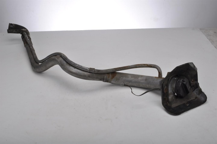
One thing was certain: the stock Fiero filler tube, purpose-bent to fit a 93.4” wheelbase, wasn’t going to fit a 96.4” wheelbase chassis, especially since the stretch was made exactly in between the tank and the fuel filler pocket:
Next up was figuring out how to route a filler neck and tube from the pocket to the tank. I decided to delve into the details just enough to satisfy myself that I wouldn’t need to relocate the filler pocket, and deal with the final installation later when I worked up the fuel system.
One thing was certain: the stock Fiero filler tube, purpose-bent to fit a 93.4” wheelbase, wasn’t going to fit a 96.4” wheelbase chassis, especially since the stretch was made exactly in between the tank and the fuel filler pocket:
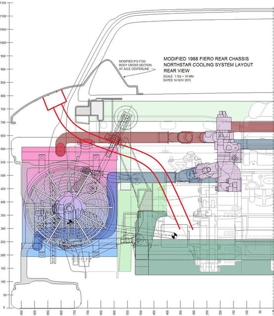
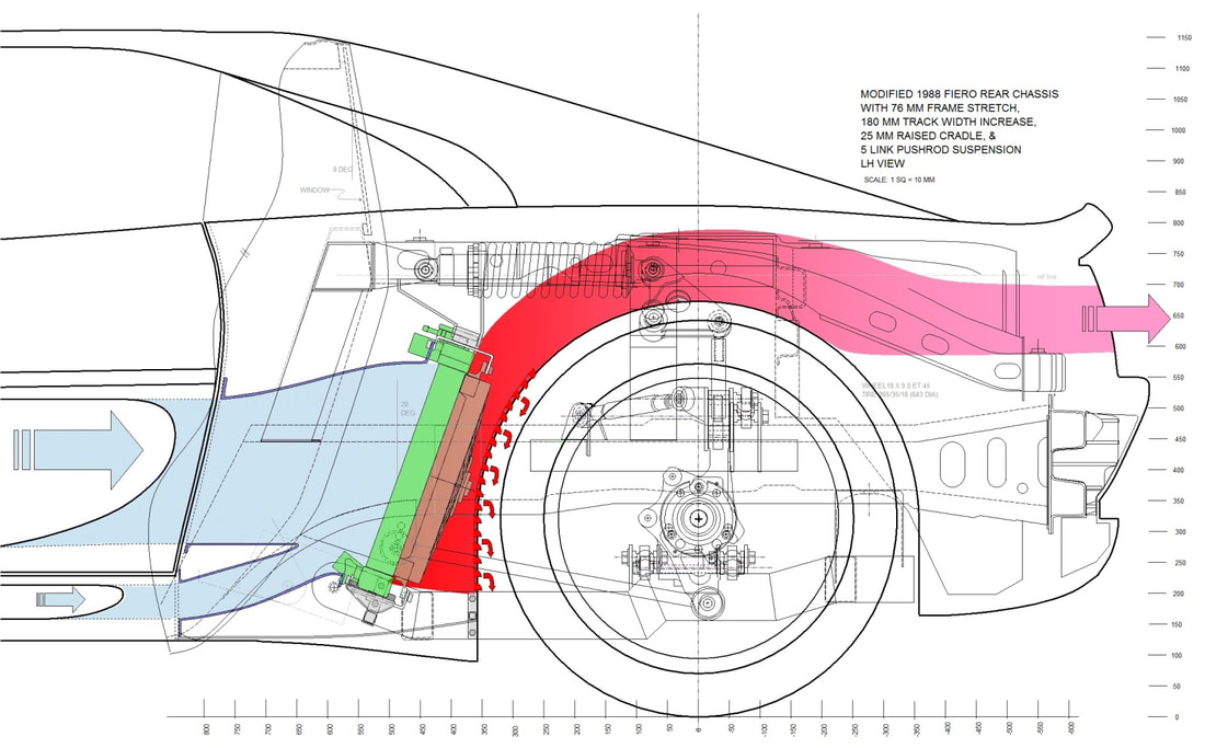
The new filler tube would have to contend with mid mounted radiators, and their hoses and mounts getting in the way:
The new filler tube would have to contend with mid mounted radiators, and their hoses and mounts getting in the way:
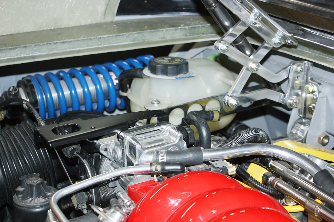
Furthermore, the F355 filler pocket was about 4” further outboard, and the tube would have to navigate around horizontal shocks, springs, and levers, a decklid hinge, and a coolant recovery bottle. This is the congested corner the fuel hose had to thread under:
Furthermore, the F355 filler pocket was about 4” further outboard, and the tube would have to navigate around horizontal shocks, springs, and levers, a decklid hinge, and a coolant recovery bottle. This is the congested corner the fuel hose had to thread under:
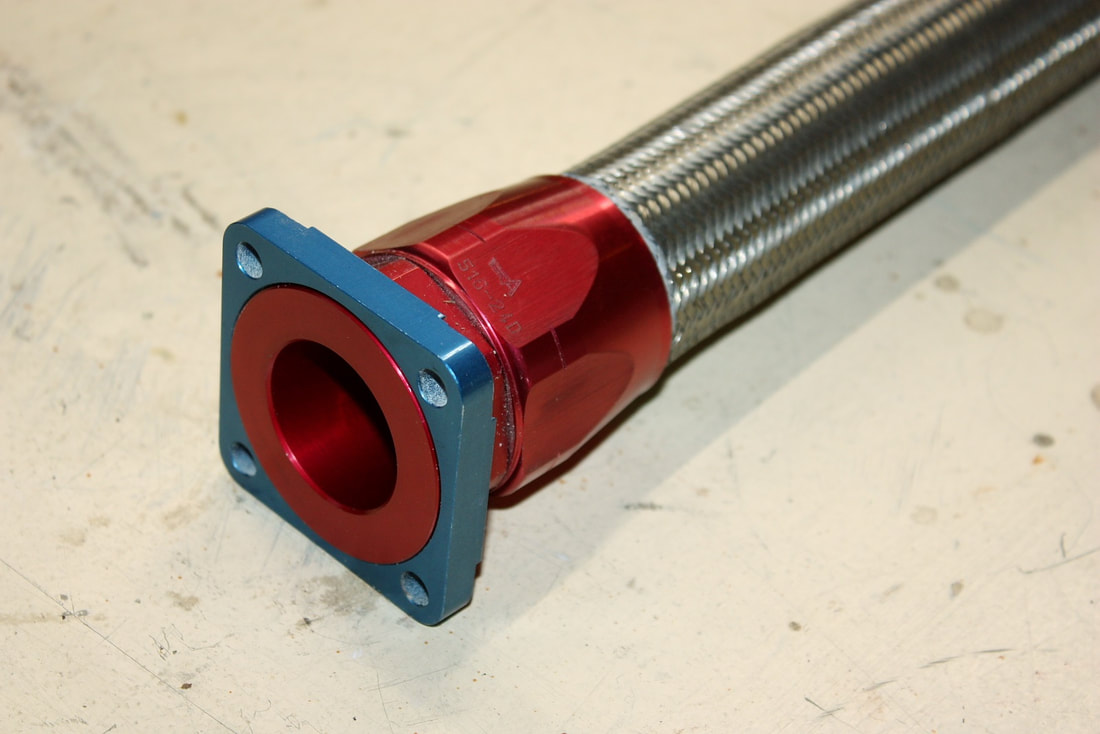
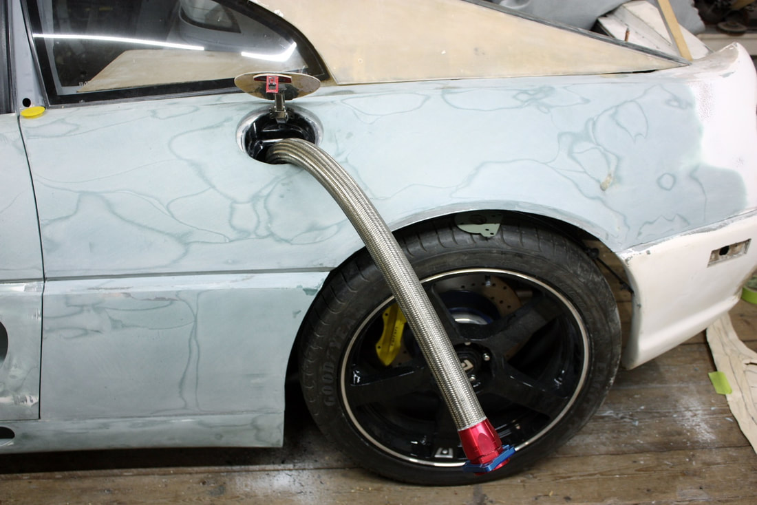
There was simply no way to route a hard filler tube with everything in the way, so the solution came in the form of a 1.25” ID fuel rated stainless steel braided flex hose from Aeroquip:
There was simply no way to route a hard filler tube with everything in the way, so the solution came in the form of a 1.25” ID fuel rated stainless steel braided flex hose from Aeroquip:
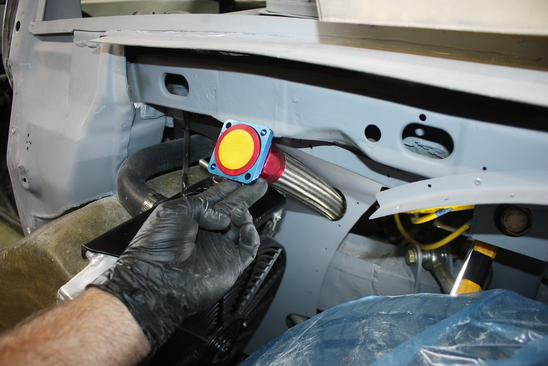
I had to make a hole in the engine bay sheet metal immediately behind the radiator to get from outside to inside the engine bay, like so:
I had to make a hole in the engine bay sheet metal immediately behind the radiator to get from outside to inside the engine bay, like so:
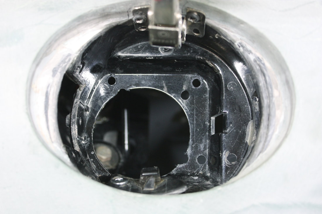
To mate the hose to the bottom of the pocket, I had to be a bit creative, but luckily the stock hole had enough excess material to allow me to fabricate and fasten an adapter plate:
To mate the hose to the bottom of the pocket, I had to be a bit creative, but luckily the stock hole had enough excess material to allow me to fabricate and fasten an adapter plate:
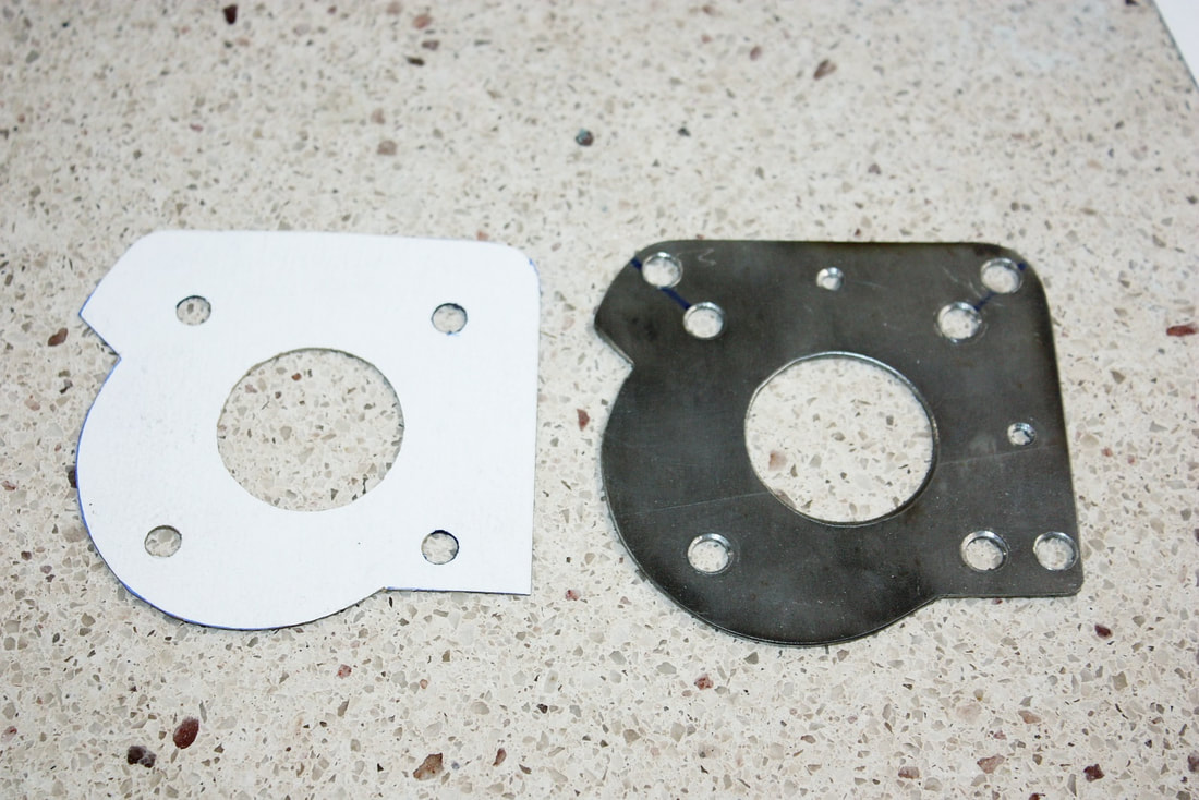
Using cardboard as a template, I made a makeshift adapter from 1/8” steel plate that mounted to the bottom of the pocket, which also allowed mounting the hose flange to the backside of the adapter with an O-ring. For this post it’s enough to show that I was able to thread the flexible hose through the filler pocket, around all the obstacles, and down to the area where the stock filler tube attaches to the tank:
Using cardboard as a template, I made a makeshift adapter from 1/8” steel plate that mounted to the bottom of the pocket, which also allowed mounting the hose flange to the backside of the adapter with an O-ring. For this post it’s enough to show that I was able to thread the flexible hose through the filler pocket, around all the obstacles, and down to the area where the stock filler tube attaches to the tank:
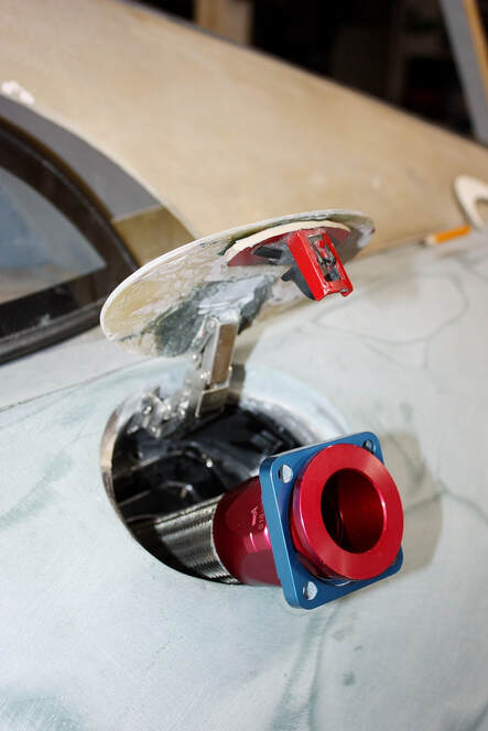
I used three Allen machine bolts to hold the adapter to the bottom of the filler pocket, and four to hold the hose flange to the back of the adapter:
I used three Allen machine bolts to hold the adapter to the bottom of the filler pocket, and four to hold the hose flange to the back of the adapter:
Later when I cover the fuel system, I’ll show how I adapted a capless filler neck, and added a vent line.
To pretty things up a bit, I cut a couple moon-shaped trim pieces from some spare fibreglass panels, and recessed and bonded them to the surround to hide the ugly seam where the plastic pocket met the fender:
Then I filled and sanded the underside of the filler door…
Then I filled and sanded the underside of the filler door…
… and filled and sanded the outer skin of the door to match the contour of the quarter panel:
… and filled and sanded the outer skin of the door to match the contour of the quarter panel:
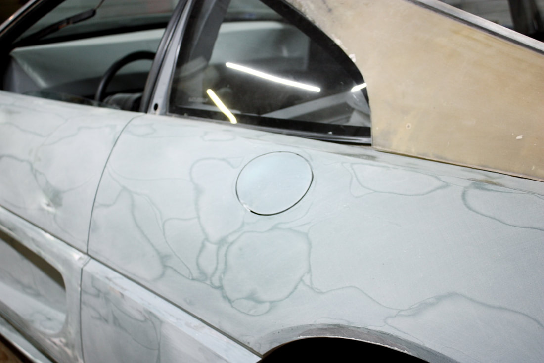
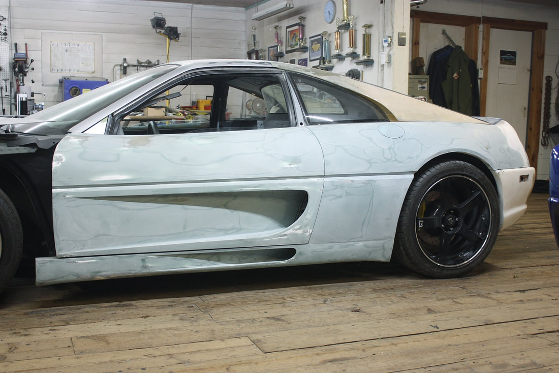
Stepping back, the quarter was nearly finished the shaping stage:
Stepping back, the quarter was nearly finished the shaping stage:
If you’ve been paying close attention all along, you might’ve noticed earlier photos giving clues about what was coming next.
Having mid-mounted radiators meant the air passing through them needed somewhere to go after it did its job. Earlier, I designed the rear wheel well liners with louvers to vent some of that air, and the rear tail light panel will be made of mesh (a-la F355 Challenge) to exhaust the rest. So functionally, nothing else was needed:
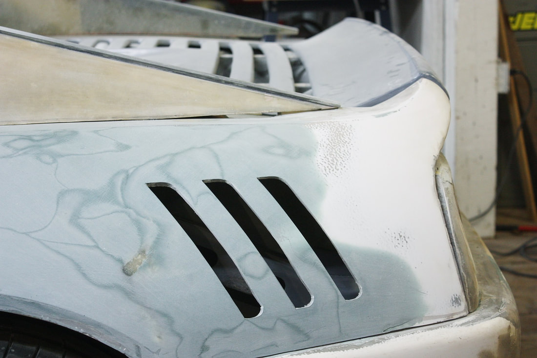
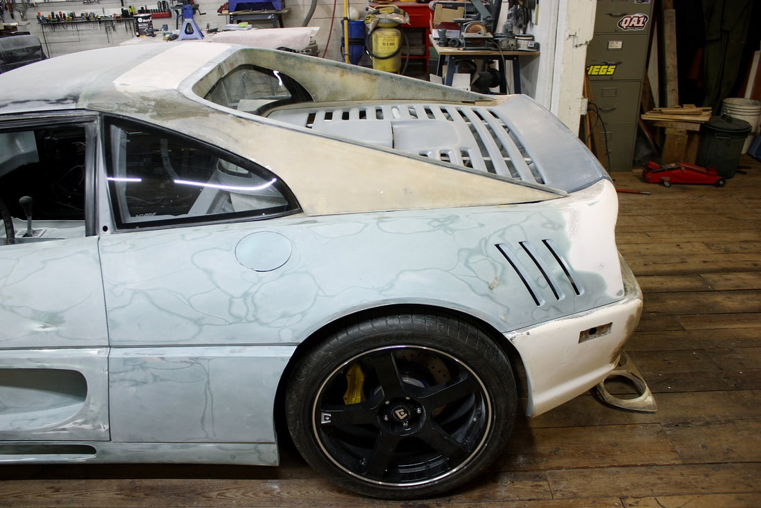
But I loved the idea of adding shark gills to the rear quarter panels, paying homage to the F40:
But I loved the idea of adding shark gills to the rear quarter panels, paying homage to the F40:
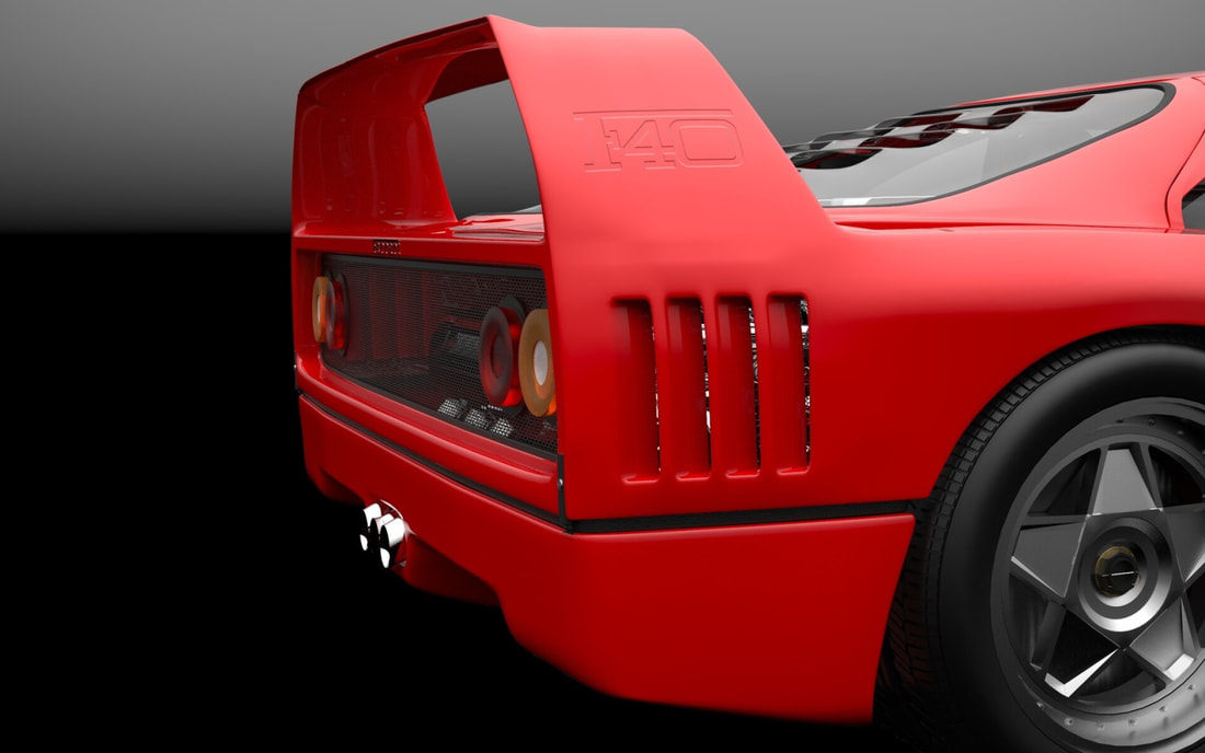
They would be mainly cosmetic, but would also add a bit more unobstructed venting for the hot air flowing through the rads.
After playing around with some masking tape at different angles and lengths, I decided to go for it and add another personal touch to my F355:
They would be mainly cosmetic, but would also add a bit more unobstructed venting for the hot air flowing through the rads.
After playing around with some masking tape at different angles and lengths, I decided to go for it and add another personal touch to my F355:
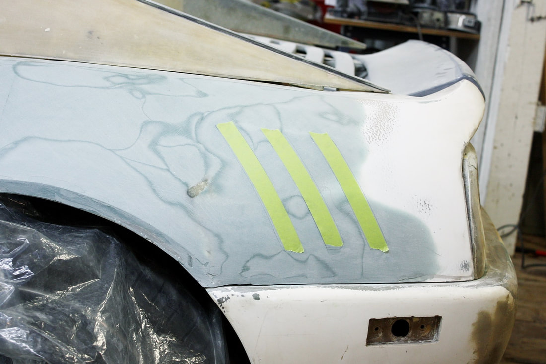
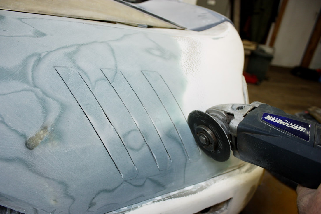
I made three different templates, each about a ¼” shorter than the previous one, then aligned them along their bottom edges parallel to the split line between the quarter and the rear fascia. That way the tops of each gill tapered more or less with the sloping line along the top of the quarter panel. Then I made the vertical slices with a thin cut off wheel in my angle grinder:
I made three different templates, each about a ¼” shorter than the previous one, then aligned them along their bottom edges parallel to the split line between the quarter and the rear fascia. That way the tops of each gill tapered more or less with the sloping line along the top of the quarter panel. Then I made the vertical slices with a thin cut off wheel in my angle grinder:
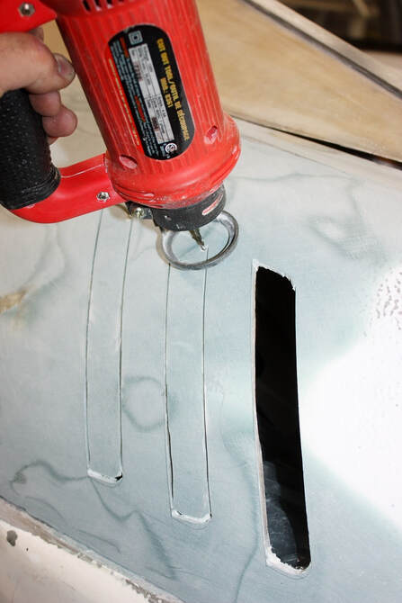
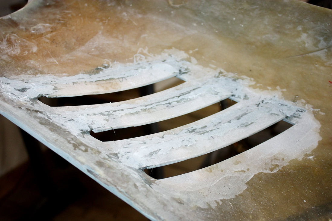
To complete the rounded corners and the short horizontal cuts, I used a rotary cut-out tool (Zippy tool) with a purpose-made router bit:
To complete the rounded corners and the short horizontal cuts, I used a rotary cut-out tool (Zippy tool) with a purpose-made router bit:
Once they were cut out, I had to remove the panel and grind the backsides surrounding each opening to an even thickness all the way around each gill, otherwise the openings looked sloppy from every angle except straight on. Here are a couple photos once the varying thickness in the panel had been addressed:
Once they were cut out, I had to remove the panel and grind the backsides surrounding each opening to an even thickness all the way around each gill, otherwise the openings looked sloppy from every angle except straight on. Here are a couple photos once the varying thickness in the panel had been addressed:
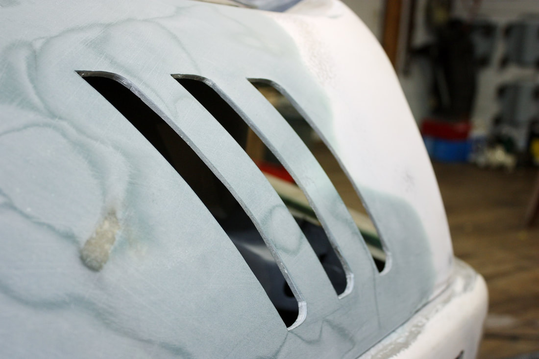
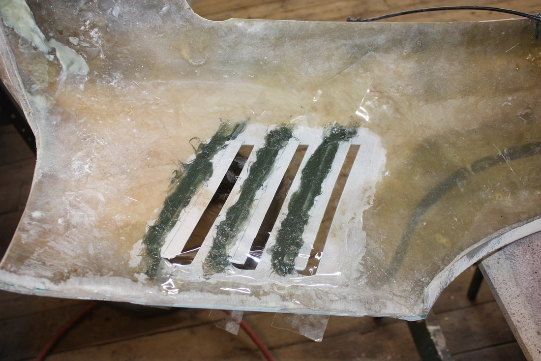
As good as I thought they looked at this point, I wasn’t finished. I wanted more than just holes in the skin… I wanted them to look like formed louvers. So I bonded the slats I had cut out to the backside of each hole like so:
As good as I thought they looked at this point, I wasn’t finished. I wanted more than just holes in the skin… I wanted them to look like formed louvers. So I bonded the slats I had cut out to the backside of each hole like so:
Then sanded them down evenly to make sure they’d look right from any angle viewed from the street side:
Then sanded them down evenly to make sure they’d look right from any angle viewed from the street side:
And finally I filled and sanded the sharp inside corners on the street-side with a gentle fillet radius:
And finally I filled and sanded the sharp inside corners on the street-side with a gentle fillet radius:
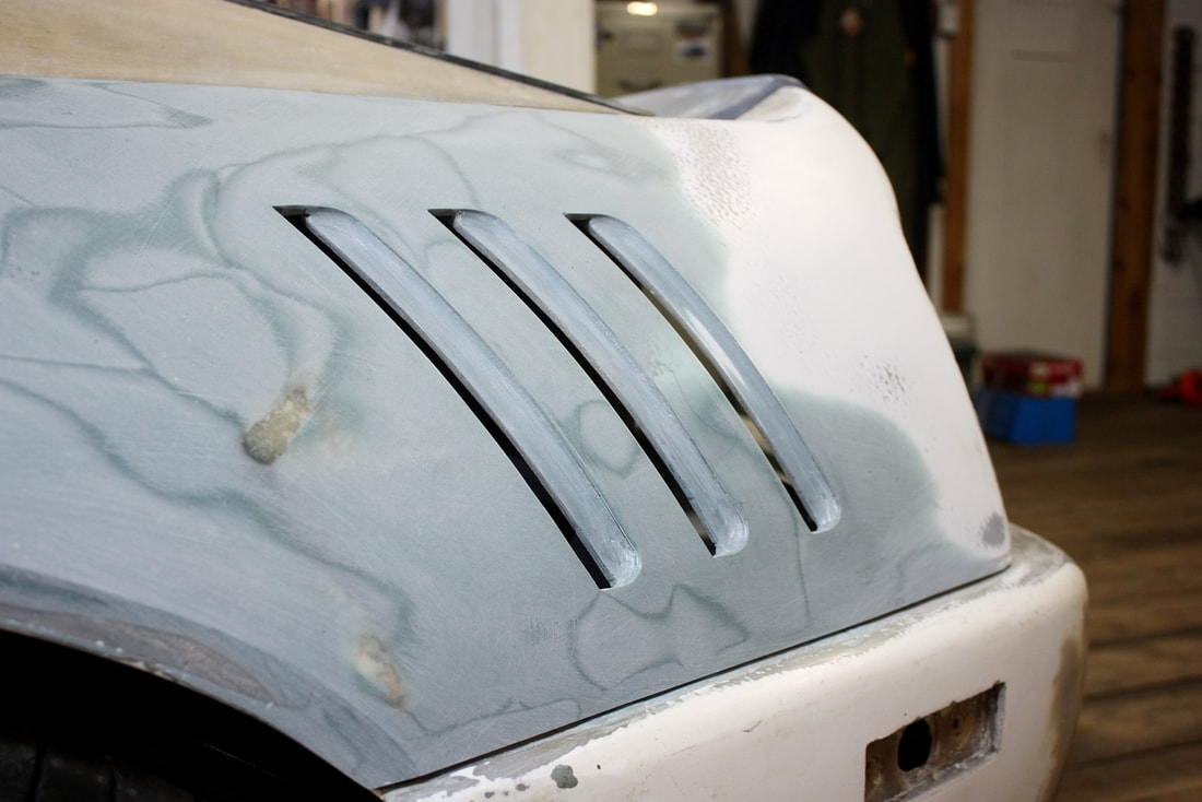
Taking a step back, I was pretty darned happy with my little customization:
Taking a step back, I was pretty darned happy with my little customization:
Next up, I delve into the passenger side rear quarter panel. Stay tuned!
Next up, I delve into the passenger side rear quarter panel. Stay tuned!

 RSS Feed
