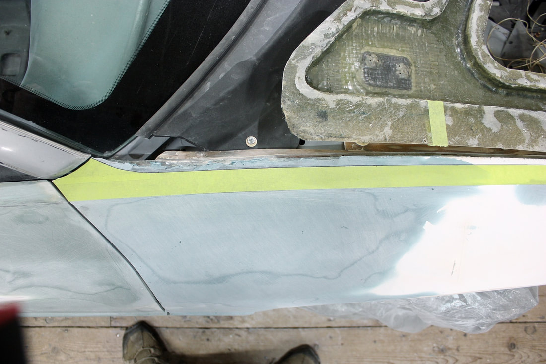
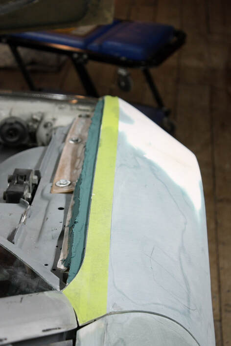
As I made my way toward the front of the fender, the next step was to widen the opening for the hood. I explained in Post #183 that the width of the fender top was all over the map. Once again, the masking tape in this next photo shows the correct width of that surface and the correct flow of lines along the hood and up the A-pillar:
As I made my way toward the front of the fender, the next step was to widen the opening for the hood. I explained in Post #183 that the width of the fender top was all over the map. Once again, the masking tape in this next photo shows the correct width of that surface and the correct flow of lines along the hood and up the A-pillar:
To address this, I needed to countersink the excess skin along the top of the fender, making the hood opening wider. One of two things was going to happen: either I’d get lucky and there would be enough panel thickness to accommodate that, or I’d end up grinding through the skin. Either way, it had to be done so I gambled and took out my 1” pneumatic sander and “had at it”:
To address this, I needed to countersink the excess skin along the top of the fender, making the hood opening wider. One of two things was going to happen: either I’d get lucky and there would be enough panel thickness to accommodate that, or I’d end up grinding through the skin. Either way, it had to be done so I gambled and took out my 1” pneumatic sander and “had at it”:
I was half lucky. Some areas the fibreglass was thick enough to support the modification…
I was half lucky. Some areas the fibreglass was thick enough to support the modification…
… while other areas were just too thin and I ended up grinding through:
… while other areas were just too thin and I ended up grinding through:
That meant an extra step was needed to reinforce the fender from underneath with a couple layers of mat:
That meant an extra step was needed to reinforce the fender from underneath with a couple layers of mat:
Once the structural repairs were made, I repaired the cosmetic damage with a coat of short strand filler on the top side, like this:
Once the structural repairs were made, I repaired the cosmetic damage with a coat of short strand filler on the top side, like this:
That solved one problem but created another… my hood was now too narrow. That’s the subject of a future post.
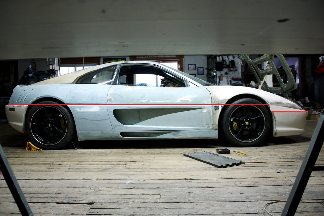
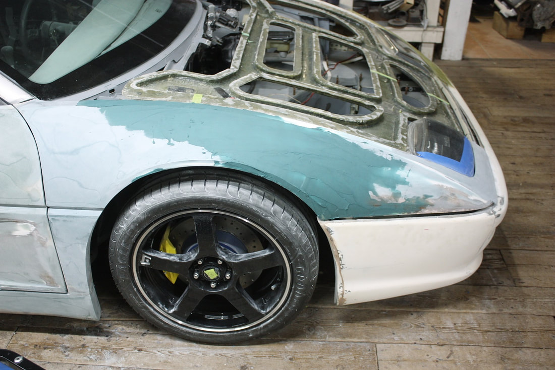
The next part of the fender I needed to fix was the belt line droop I mentioned in Post #183… here’s a reminder of the problem:
That solved one problem but created another… my hood was now too narrow. That’s the subject of a future post.
The next part of the fender I needed to fix was the belt line droop I mentioned in Post #183… here’s a reminder of the problem:
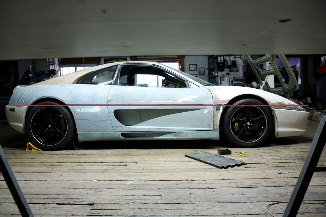
It’s bad considering it should be a straight line, but even if I weren’t able to do anything about it, my car wouldn’t be the only Ferrari with an unsightly droop… have a look at the iconic F40:
It’s bad considering it should be a straight line, but even if I weren’t able to do anything about it, my car wouldn’t be the only Ferrari with an unsightly droop… have a look at the iconic F40:
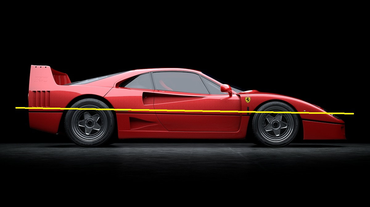
You’ll never look at an F40 the same way again! This does however illustrate how big details like this can go unnoticed when you’re distracted by the overall picture.
One way to partially solve the problem on my car would have been to graft a wedge shaped addition to the fender like this:
You’ll never look at an F40 the same way again! This does however illustrate how big details like this can go unnoticed when you’re distracted by the overall picture.
One way to partially solve the problem on my car would have been to graft a wedge shaped addition to the fender like this:
Look carefully for the grey triangular insert in the photo above. This mod would’ve leveled the belt line but it also would’ve lowered it considerably too. It also gave the fender a lot more visible “weight” making the nose look bulbous.
Besides, upon closer inspection, it appeared the former owner had already grafted a triangular filler piece just like this and it still didn’t look right!
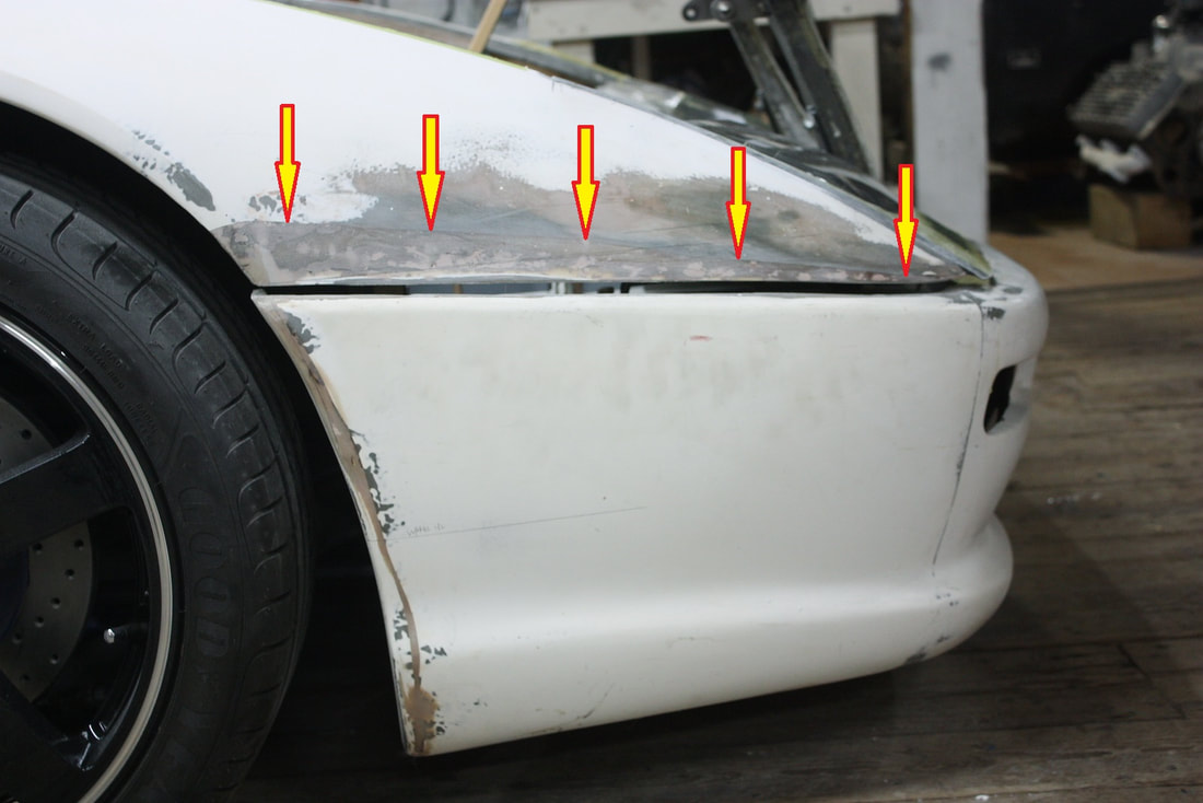
The alternative was to tilt the front of the fender and fascia upward, reducing the slope and reducing the height difference between the two lines:
The alternative was to tilt the front of the fender and fascia upward, reducing the slope and reducing the height difference between the two lines:
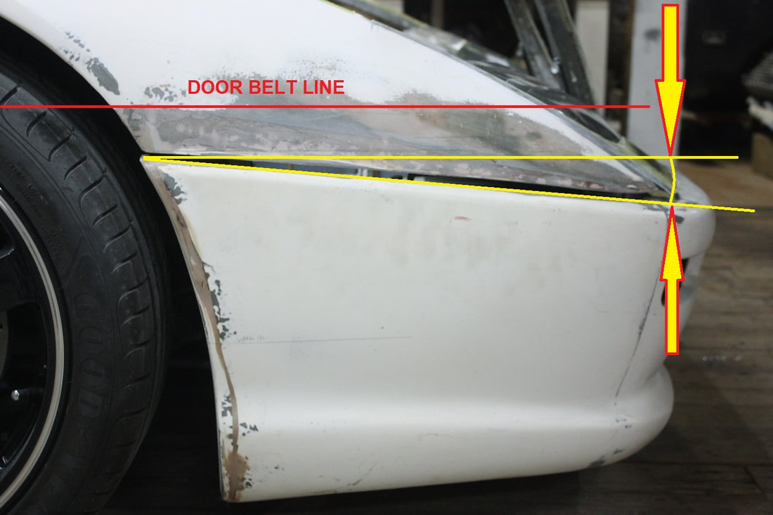
Doing so would raise the fender around the headlight surround so I’d need to raise the headlights a bit, and I’d have to check if it threw off any of the swoopy upper body lines too.
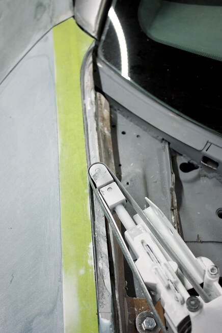
I tested the idea by inserting shims under the front fascia mounting tabs (this photo is from a while ago, but it clearly shows where I mean):
Doing so would raise the fender around the headlight surround so I’d need to raise the headlights a bit, and I’d have to check if it threw off any of the swoopy upper body lines too.
I tested the idea by inserting shims under the front fascia mounting tabs (this photo is from a while ago, but it clearly shows where I mean):
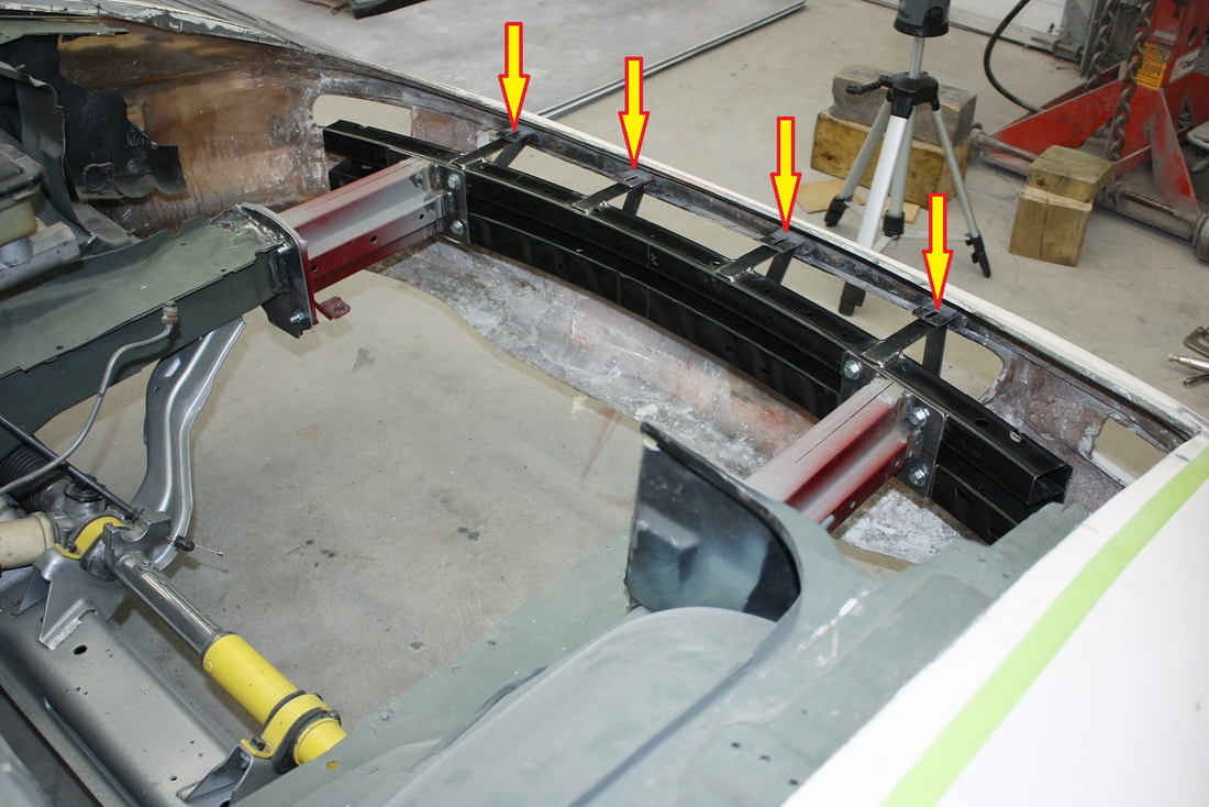
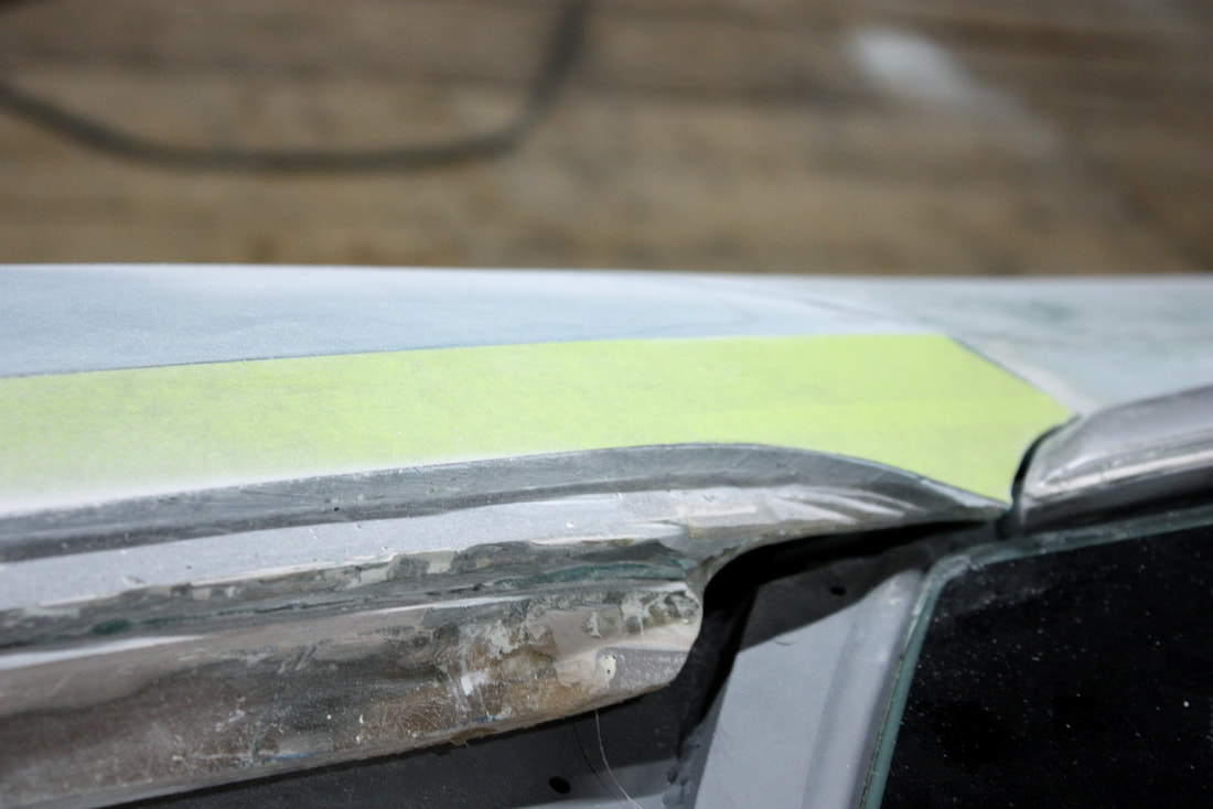
After experimenting a bit, I found I could raise the front by about a ½” without affecting the flow of the other body lines. That’s the most I could do to address the droopy belt line without a wholesale redesign of the front end, and I was much too far along to consider that. Here’s the result:
After experimenting a bit, I found I could raise the front by about a ½” without affecting the flow of the other body lines. That’s the most I could do to address the droopy belt line without a wholesale redesign of the front end, and I was much too far along to consider that. Here’s the result:
Back-tracking in my story line here, you may recall from Post #126 that I decided to make a one-piece wrap-around front fender panel incorporating both fenders and the thin trim piece across the front of the hood:
Back-tracking in my story line here, you may recall from Post #126 that I decided to make a one-piece wrap-around front fender panel incorporating both fenders and the thin trim piece across the front of the hood:
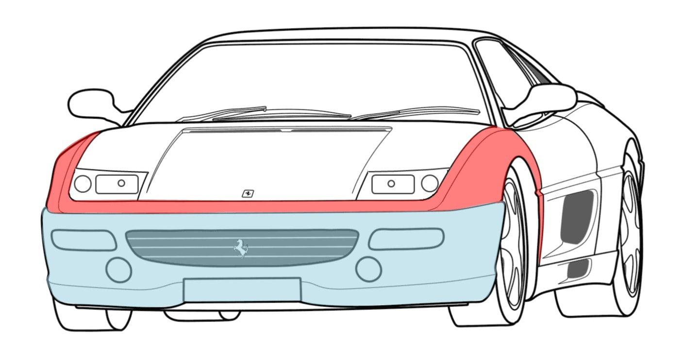
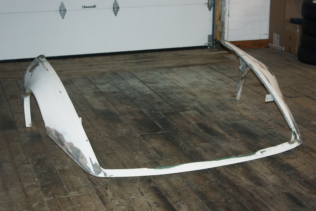
Even though I had reinforced the thin front piece with a steel angle, the entire piece was just too awkward to handle, so I cut it up into three more manageable fibreglass pieces, and bolted the reinforcing angle to the chassis by itself.
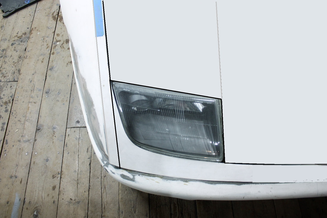
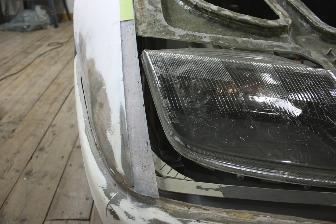
That decision combined with the need to make new headlight surrounds forced me to decide whether I wanted the new headlight surrounds to be integral to the nose trim piece, like this:
Even though I had reinforced the thin front piece with a steel angle, the entire piece was just too awkward to handle, so I cut it up into three more manageable fibreglass pieces, and bolted the reinforcing angle to the chassis by itself.
That decision combined with the need to make new headlight surrounds forced me to decide whether I wanted the new headlight surrounds to be integral to the nose trim piece, like this:
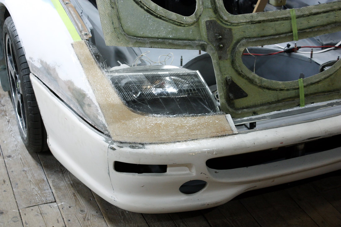
Or to make the new headlight surrounds integral to the fender, and shorten the trim piece like this:
Or to make the new headlight surrounds integral to the fender, and shorten the trim piece like this:

After about twice as much deliberation as the issue deserved, I opted for design #2. I personally found it more aesthetically pleasing, and it avoided having to make long slender and potentially fragile spears near the upper aft corners of the headlights of the first design.
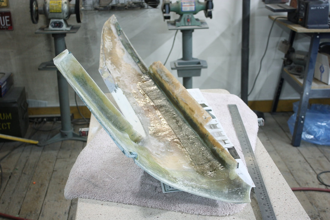
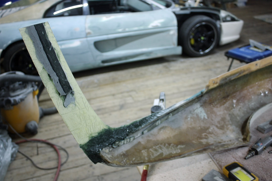
So I made up a cardboard template, then cut out a piece of fibreglass reinforced plastic (cheap shower wall paneling) as a base for a mold form:
After about twice as much deliberation as the issue deserved, I opted for design #2. I personally found it more aesthetically pleasing, and it avoided having to make long slender and potentially fragile spears near the upper aft corners of the headlights of the first design.
So I made up a cardboard template, then cut out a piece of fibreglass reinforced plastic (cheap shower wall paneling) as a base for a mold form:
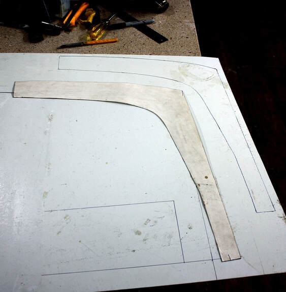
Next I pinned the FRP form to the fender to get the correct curvature, and laid up three layers of mat on the form:
Next I pinned the FRP form to the fender to get the correct curvature, and laid up three layers of mat on the form:
I protected the headlight lens and front fascia with clear packing tape to make any spilled resin an easy clean-up.
Once the resin had hardened and I was able to remove the new headlight surround off the form, I trimmed it to the exact shape I needed, and then prepped the fender top to flush mount it. I ground down a strip alongside the headlight which also served to roughen up the surface for bonding:
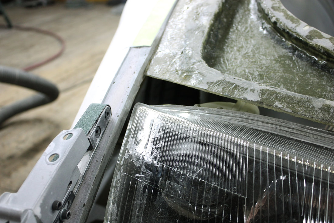
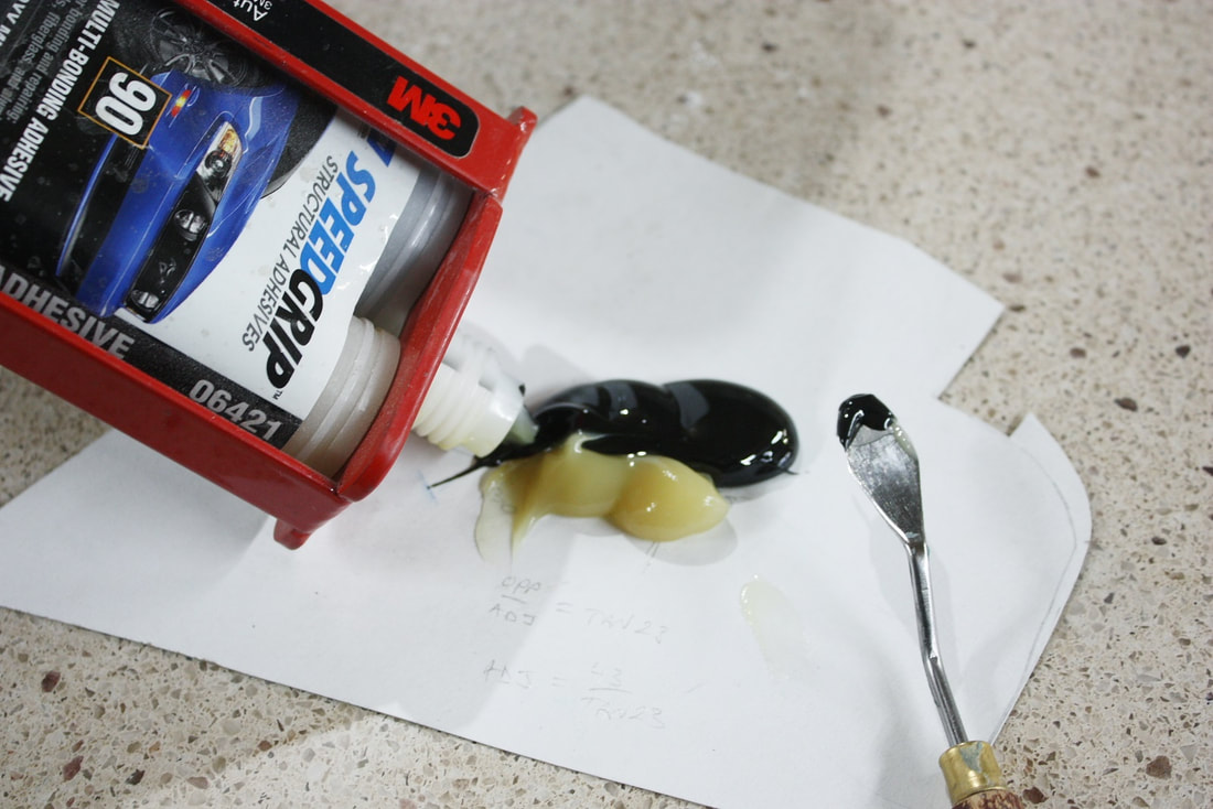
Using 90 minute epoxy, I then bonded the surround to the fender top:
Using 90 minute epoxy, I then bonded the surround to the fender top:
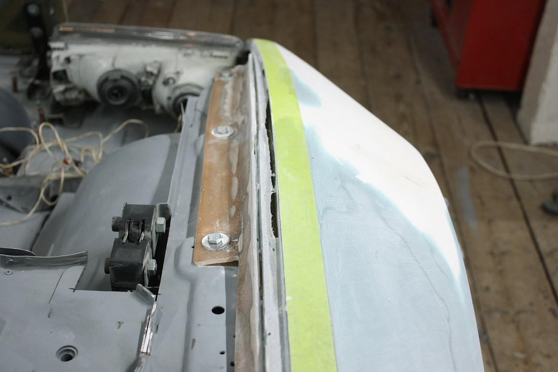
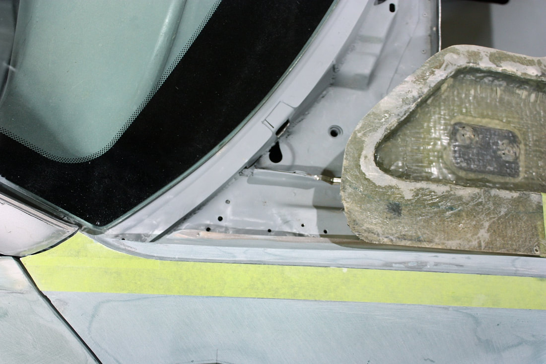
I also built up a mounting pad under the other end of the surround using some long strand filler to keep it the right height in front of the headlight. Again, by using packing tape on the metal reinforcement bar underneath it, the filler only stuck to the fibreglass surround and not to the metal angle:
I also built up a mounting pad under the other end of the surround using some long strand filler to keep it the right height in front of the headlight. Again, by using packing tape on the metal reinforcement bar underneath it, the filler only stuck to the fibreglass surround and not to the metal angle:
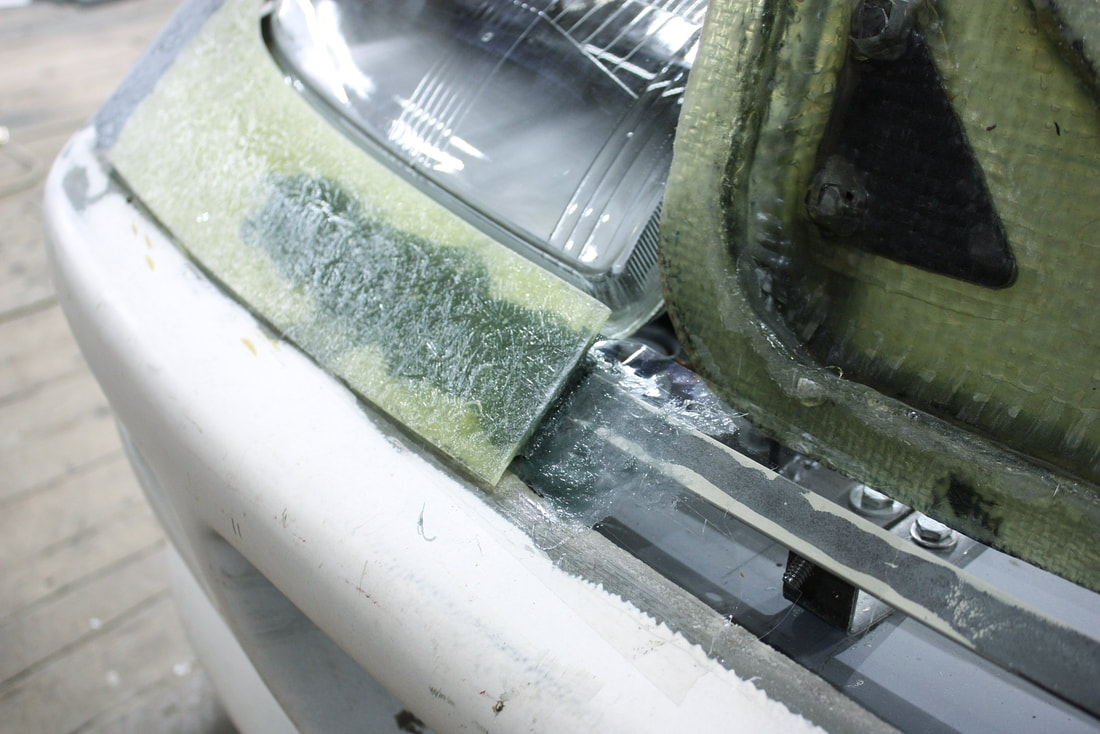
I added more long strand where the two pieces met, to act like a fillet.
I added more long strand where the two pieces met, to act like a fillet.
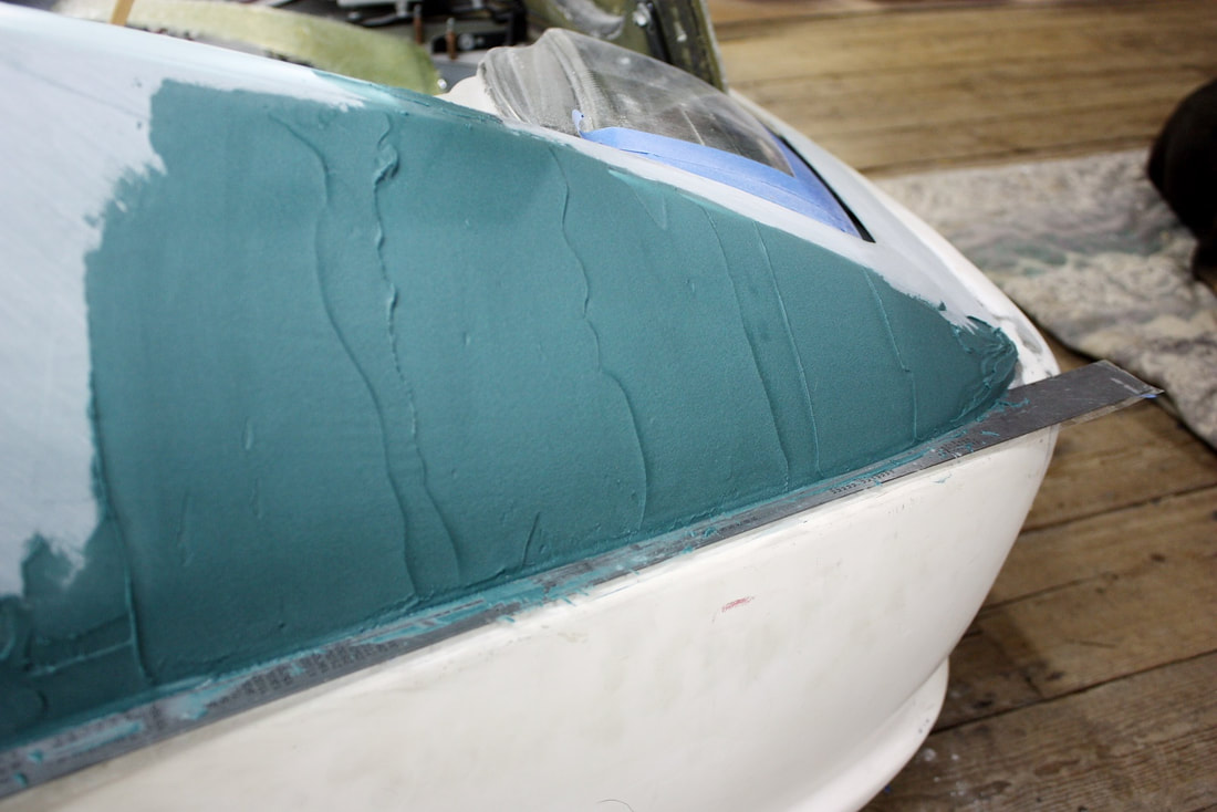
After shaping the long strand, I reinstalled the fender and continued blending the various mods with a skim coat of short strand filler. (Here I had propped up the fender a little higher to help with my sanding):
After shaping the long strand, I reinstalled the fender and continued blending the various mods with a skim coat of short strand filler. (Here I had propped up the fender a little higher to help with my sanding):
Then I straightened and closed up the seam between the lower fascia and the fender using a long stainless straight-edge covered in packing tape to define the line:
Then I straightened and closed up the seam between the lower fascia and the fender using a long stainless straight-edge covered in packing tape to define the line:
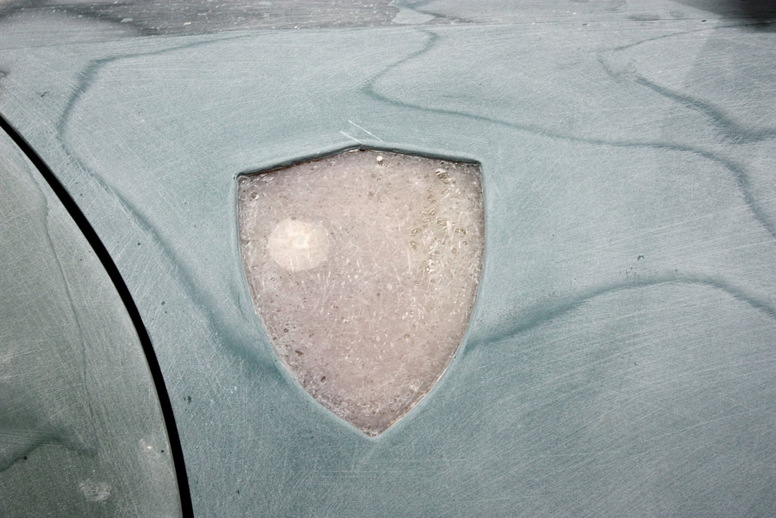
The last detail at this stage of body prep was to make an embossed area for the “Scuderia Ferrari” fender badge. Deciding exactly where it should go was a bit tricky because internet photos and measurements showed them all over the place.
I learned that the key was look for cars where the badges weren’t surface mounted like this…:

…but instead were countersunk into the fender like this:
…but instead were countersunk into the fender like this:

Apparently, factory mounted badges use the more expensive embossed fenders, so many people forego the additional expense and stick their own aftermarket badges on non-embossed fenders. Some even post measurements of where they’re supposed to go, but it’s hard to know if they did their research or simply guessed. Anyway, that accounted for the scatter in the shield’s position in most photos.
Even with that info in hand, it still boiled down to placing the shield where it pleased my eye the most. I went with about an inch closer to the door, and an inch lower than authentic F355's.
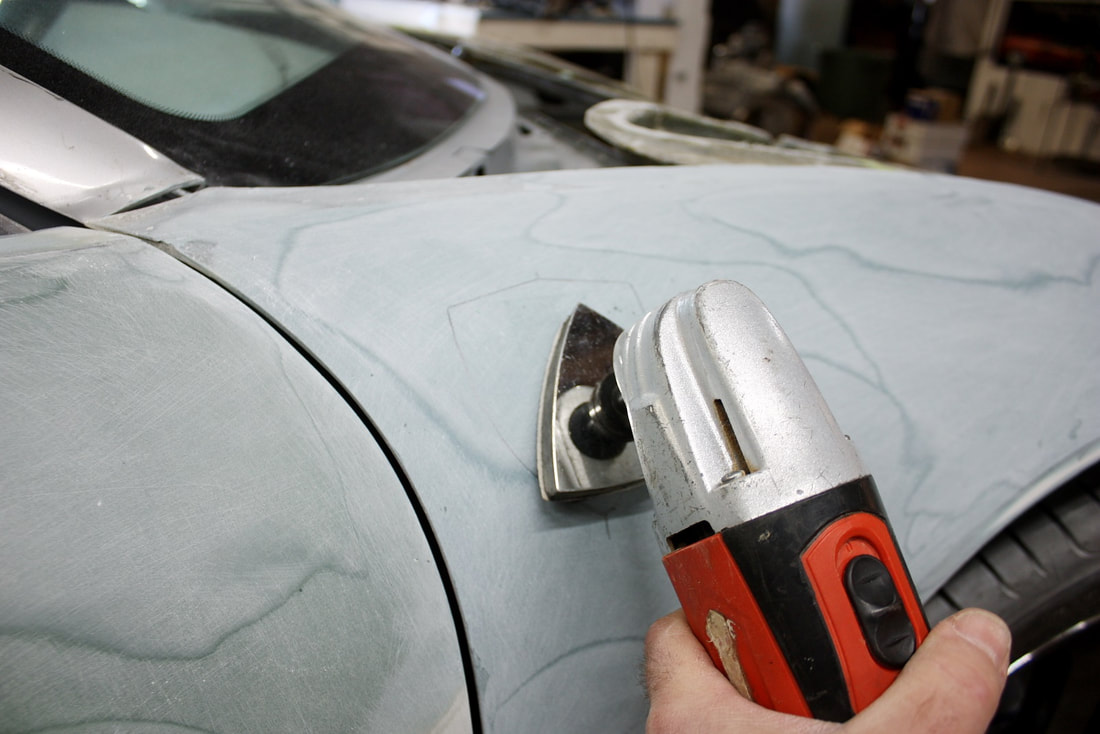
Once I had chosen the site, I used several tools including a multi-tool with triangular sanding head, a Dremel with a flat sanding disk, and a sanding drum to dig down into the fender:
Apparently, factory mounted badges use the more expensive embossed fenders, so many people forego the additional expense and stick their own aftermarket badges on non-embossed fenders. Some even post measurements of where they’re supposed to go, but it’s hard to know if they did their research or simply guessed. Anyway, that accounted for the scatter in the shield’s position in most photos.
Even with that info in hand, it still boiled down to placing the shield where it pleased my eye the most. I went with about an inch closer to the door, and an inch lower than authentic F355's.
Once I had chosen the site, I used several tools including a multi-tool with triangular sanding head, a Dremel with a flat sanding disk, and a sanding drum to dig down into the fender:
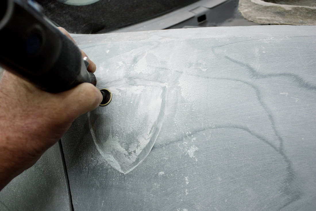
I had bought a pair of enameled cloisonné “SF” fender shields a while back, and kept test-fitting one to check the correct depth and shape. Luckily there was lots of thickness to the fibreglass in this area so I didn’t need to worry about cutting through:
I had bought a pair of enameled cloisonné “SF” fender shields a while back, and kept test-fitting one to check the correct depth and shape. Luckily there was lots of thickness to the fibreglass in this area so I didn’t need to worry about cutting through:

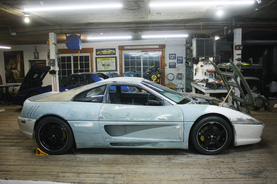
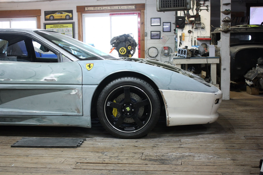
Stepping back, I was happy the fender looked the part given its humble beginnings:
Stepping back, I was happy the fender looked the part given its humble beginnings:
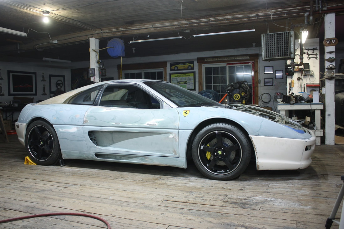
Next up: the driver’s side front fender. (I’ll be glad to move on to the rest of the body where there isn’t two of everything!)
Next up: the driver’s side front fender. (I’ll be glad to move on to the rest of the body where there isn’t two of everything!)

 RSS Feed
