The next big body panel was the hood, but as with any project of this scope, a bunch of prep work had to be done first. Before the hood could be added, I needed to locate the hinges, however, before I could locate the hinges, I needed to make sure they wouldn’t interfere with the headlights. That meant designing the front compartment first, so I could figure out how and where I’d mount the headlights!
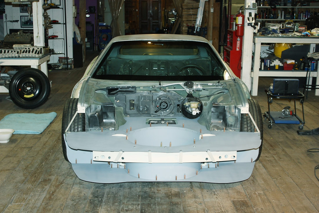
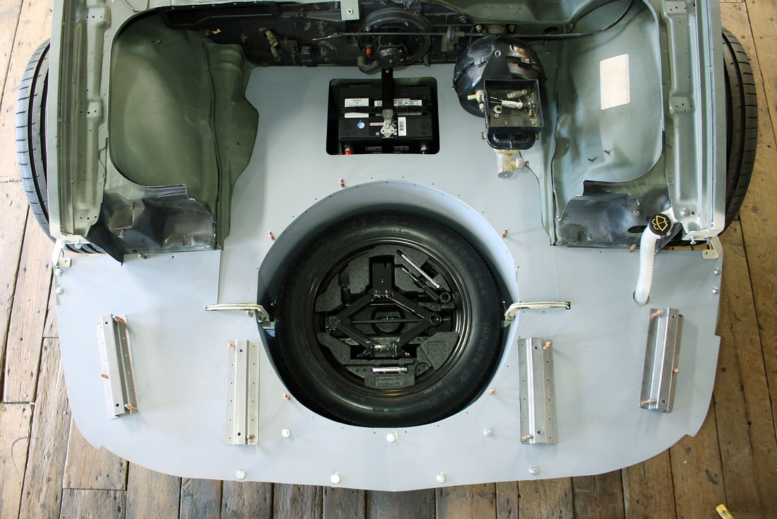
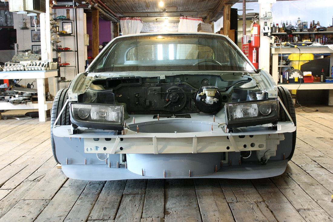
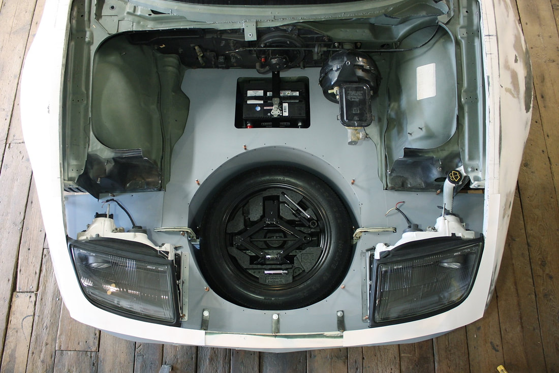
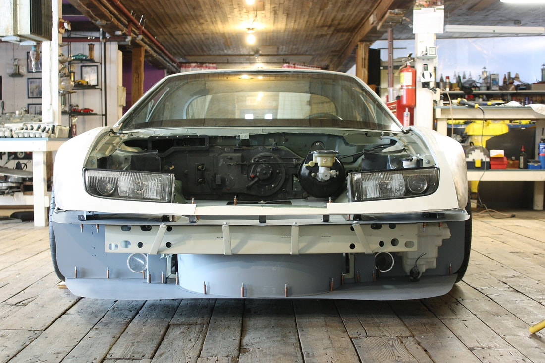
Naturally, designing the front compartment had its own complexities including considerations for the luggage compartment, spare tire, battery, windshield washer bottle, horns, and so on. So despite the numerical order of this post, chronologically I completed the front compartment next. The work is covered in Posts #107 to #111 in the Chassis section, which concludes with the front end looking like this, ready for the headlights:
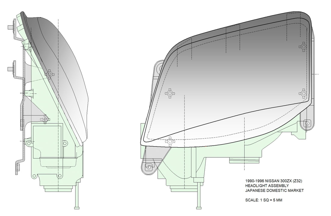
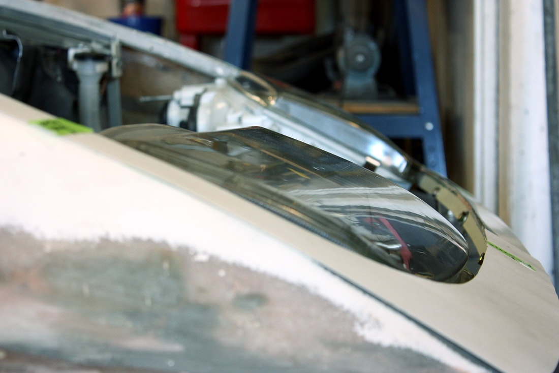
As I first mentioned back in Post #125, I had decided to personalize my F355 by ditching the failure-prone pop-up headlights for something with fewer moving parts and a more modern look. After searching the market I came across one example that had been retrofitted with late model Corvette lights, but they really didn’t fit the existing bodywork. Then I stumbled upon the 1990-1996 Nissan 300ZX (Z32) peepers which looked sleek and appeared to have a curvature that would be complimentary to my car:
As I first mentioned back in Post #125, I had decided to personalize my F355 by ditching the failure-prone pop-up headlights for something with fewer moving parts and a more modern look. After searching the market I came across one example that had been retrofitted with late model Corvette lights, but they really didn’t fit the existing bodywork. Then I stumbled upon the 1990-1996 Nissan 300ZX (Z32) peepers which looked sleek and appeared to have a curvature that would be complimentary to my car:
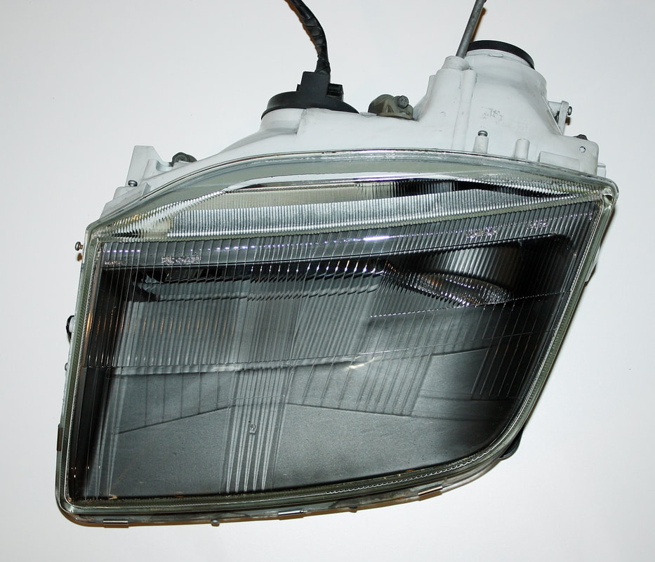
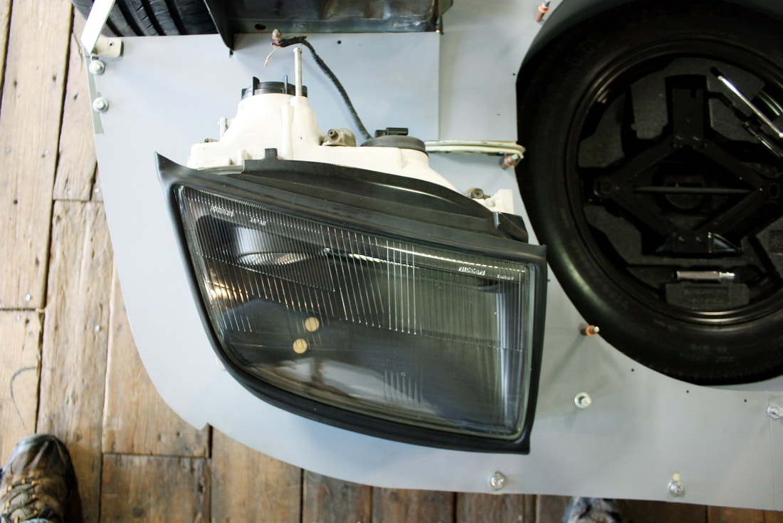
Their super low profile meant there was a chance I’d be able to make them fit within the space I had available, and to the contours of the fenders and front fascia:
I ordered a pair from a reputable salvage yard in the US, and much to my relief they flowed really nicely with the surrounding body panels when I mocked them up several months ago:
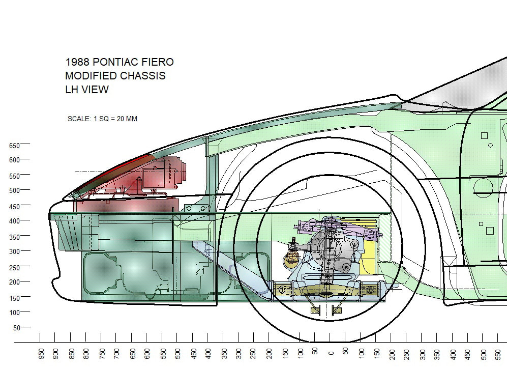
As time permitted, I set about sketching them up to add to my chassis drawings:
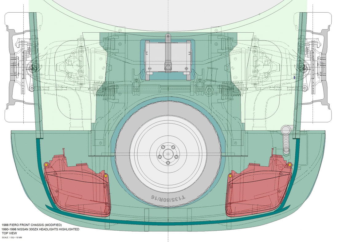
Then added them to the overhead view:
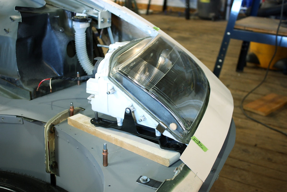
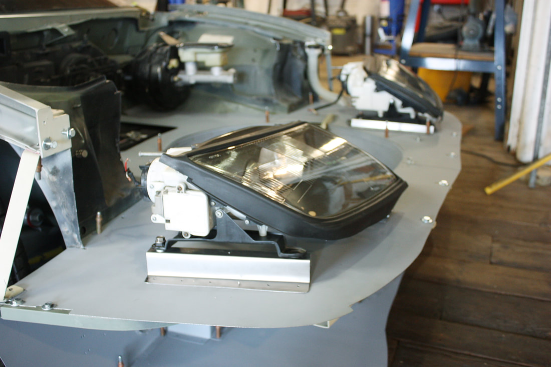
Some advance planning paid off when I constructed the luggage compartment floor low enough to not cause problems with mounting the headlights. In fact, I had about 40 mm of extra clearance below the lights to make very specific brackets to raise them to the correct height:
Some advance planning paid off when I constructed the luggage compartment floor low enough to not cause problems with mounting the headlights. In fact, I had about 40 mm of extra clearance below the lights to make very specific brackets to raise them to the correct height:
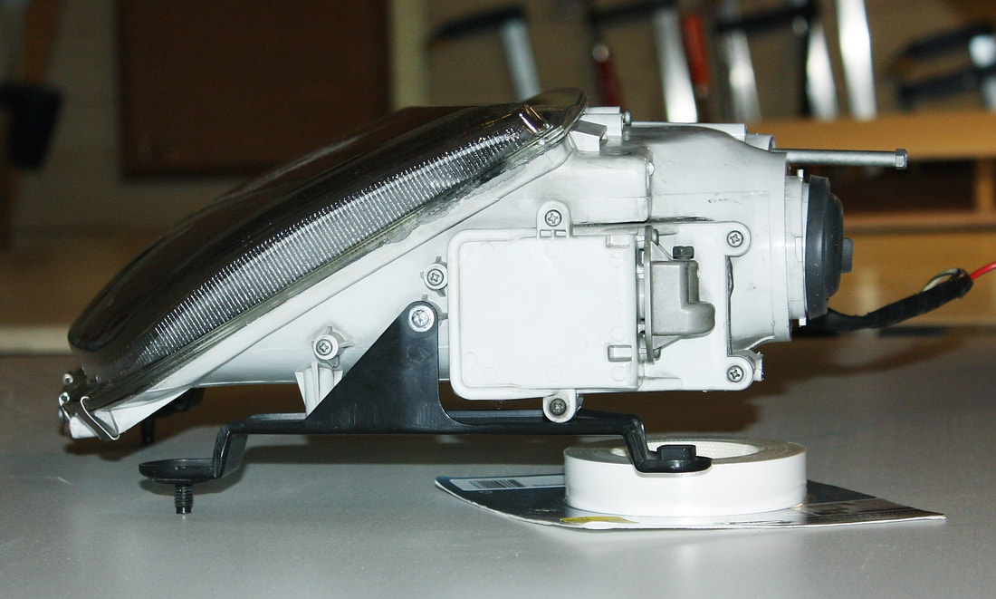
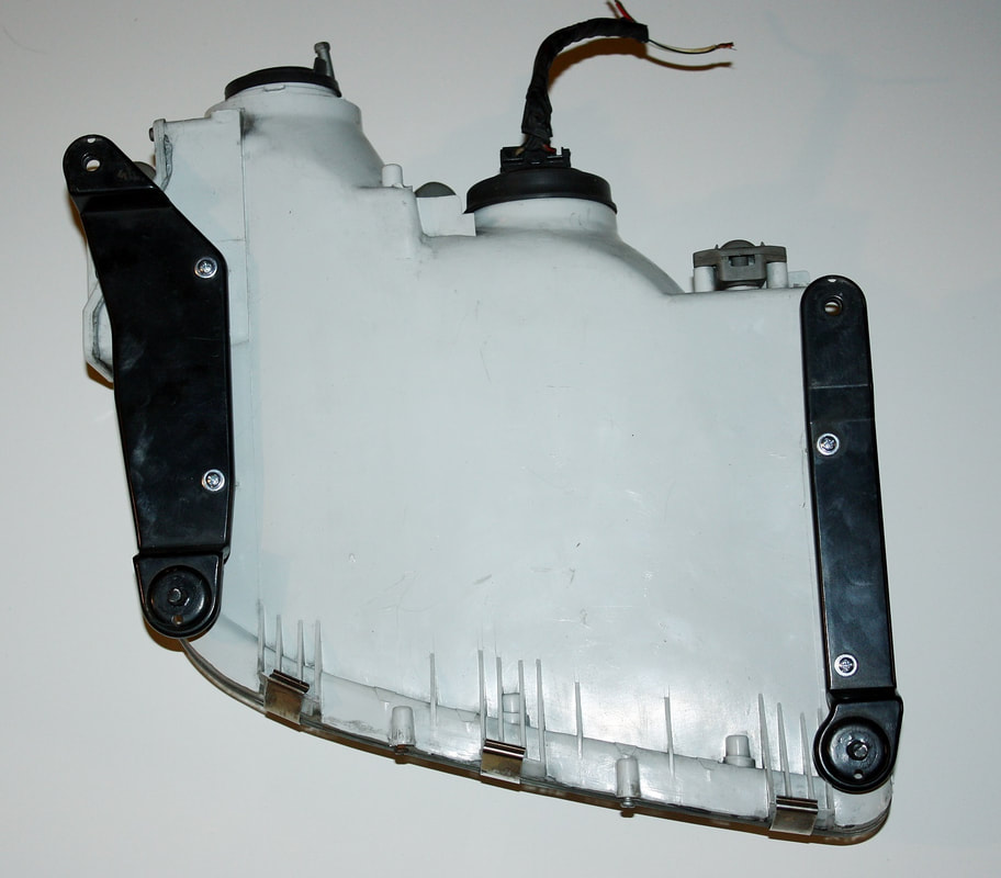
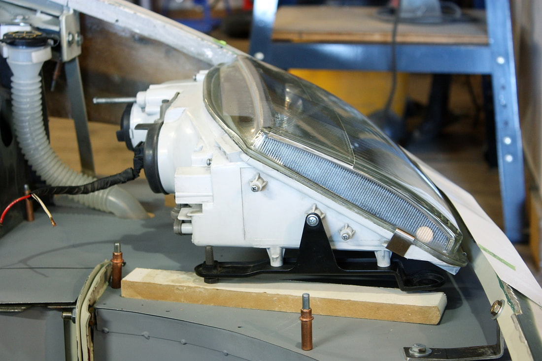
The OEM mounting system seemed pretty straight forward with two adaptable pairs of legs screwed to the flat underside of the assemblies:
It was about at this point that I realized that mounting the headlights wouldn’t be as simple as I'd imagined. The fact is, the two headlights must be mounted at the same vertical, lateral, and longitudinal distances from the centerline of the chassis, and clocked at the same rotational orientation, and tilted equally left to right, and fore and aft, for several reasons:
a. to make the four corners of the headlights align with adjacent body panels; and
b. to remain within the relatively small adjustment range of the aiming mechanisms.
It simply isn’t enough to mount the headlights “wherever", then adjust the beams to be at the same height and position on a wall 25 feet away. That only works for that very specific position. Instead, the headlights had to be mounted so that the pair of beams would be parallel to each other and at equal heights at any distance ahead of the car.
So, since I had fabricated the entire frame ahead of the front wheels, it was time to make sure I would be starting from a level base. I used my laser level to level out the chassis on my uneven wooden floors, then I checked and tweaked the luggage compartment floor to make certain it was level with the chassis. It took about a day to do this.
Next, I mocked up the headlights using wooden blocks to make up most of the additional height I needed, but then I also screwed a couple of bolts into the rear headlight mounts to make fine adjustments:
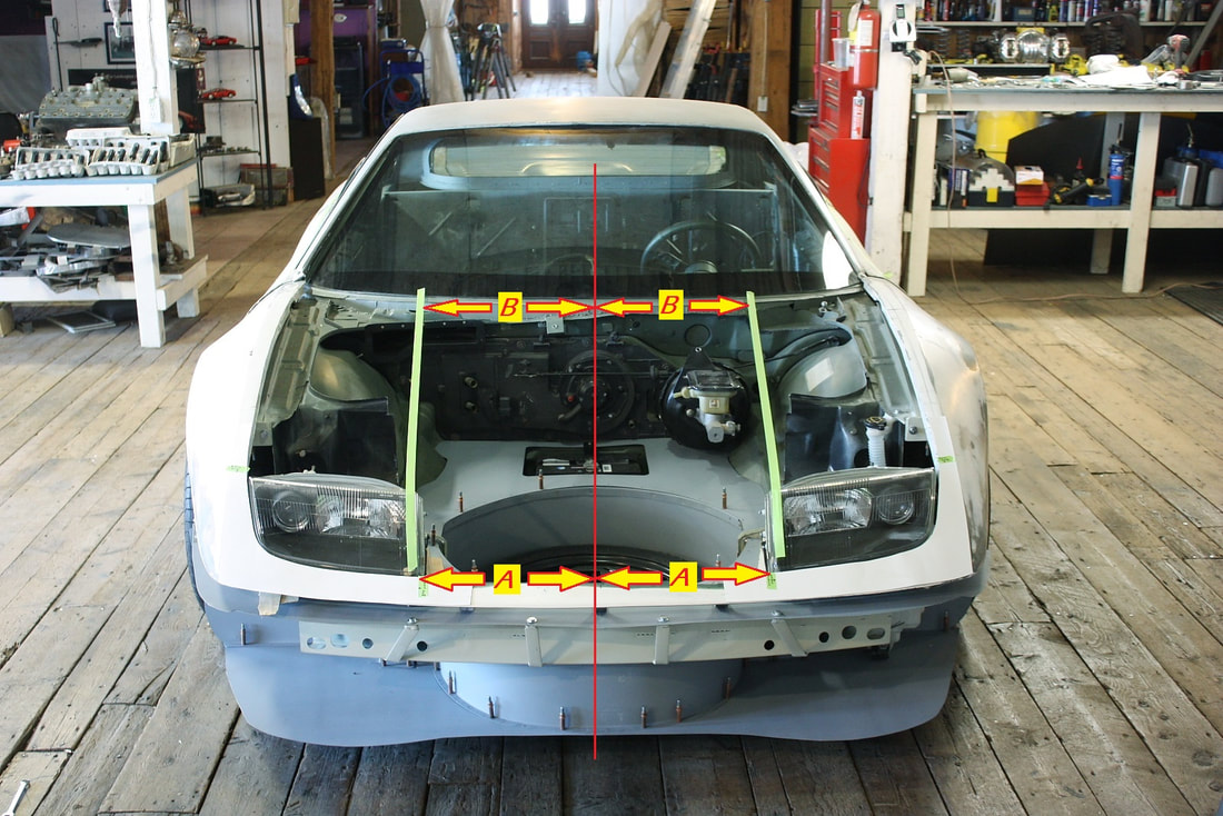
To set an equal distance between the lights, I shot the vertical beam of the laser up the centerline of the car using the mill and drill pads as reference points, and marked the locations for the inside front corners of the lights (arrows A).
To make sure they were identically clocked, I next ran beams up the inside edge of both lights (see green tape below) and made sure they intersected the cowl at the same distance from the centerline of the cowl… like this (arrows B):
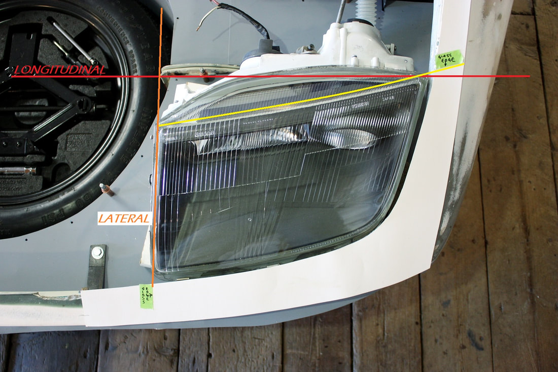
I shone a similar laser beam across the car (red line) to locate the headlights at the same longitudinal (fore and aft) locations, and used tape to mark the corners on the fenders:
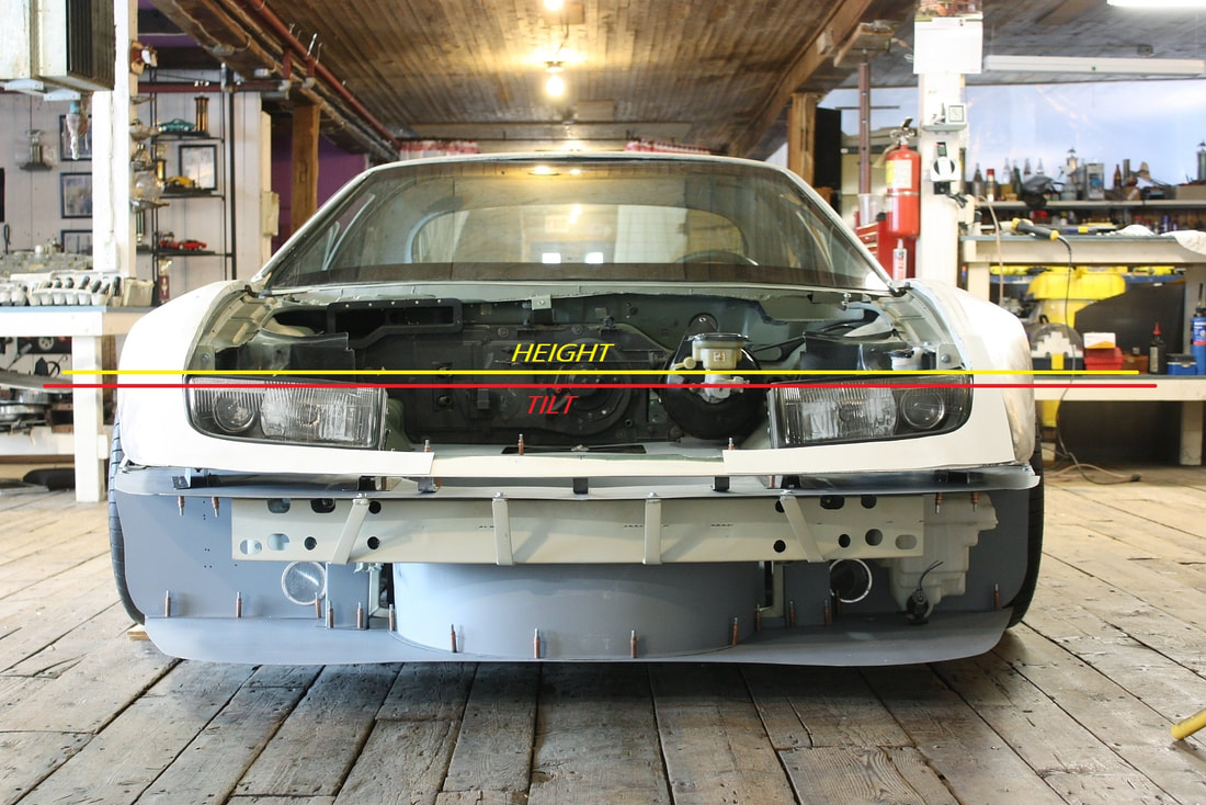
Finally, I shone the laser horizontally from the front to adjust both headlights to the same height. By having first levelled the outboard corners to each other (yellow line) and then the inboard corners (red line), I killed two birds with one stone: height and tilt:
Finally, I shone the laser horizontally from the front to adjust both headlights to the same height. By having first levelled the outboard corners to each other (yellow line) and then the inboard corners (red line), I killed two birds with one stone: height and tilt:
After that exercise, I was pretty confident the lights were very close to being at exact mirror image locations to each other with respect to the chassis. That meant I could take final measurements of the height and location of the four corners on the Nissan mounting brackets, and get rid of my wooden shims:
After that exercise, I was pretty confident the lights were very close to being at exact mirror image locations to each other with respect to the chassis. That meant I could take final measurements of the height and location of the four corners on the Nissan mounting brackets, and get rid of my wooden shims:
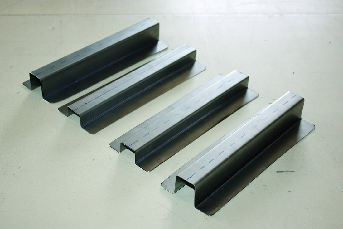
A quick zip-zap with a cut-off wheel made short work of getting four pieces of sheet metal ready for the bender. Notice the two outer mounts were made taller than the inner mounts:
A quick zip-zap with a cut-off wheel made short work of getting four pieces of sheet metal ready for the bender. Notice the two outer mounts were made taller than the inner mounts:
I screwed my new mounts to the bottom of the headlight assemblies, reset the lights in place, and marked the location of the mounts on the luggage compartment floor. Then I disassembled them again and drilled the rivet holes to attach the mounts to the floor:
I screwed my new mounts to the bottom of the headlight assemblies, reset the lights in place, and marked the location of the mounts on the luggage compartment floor. Then I disassembled them again and drilled the rivet holes to attach the mounts to the floor:
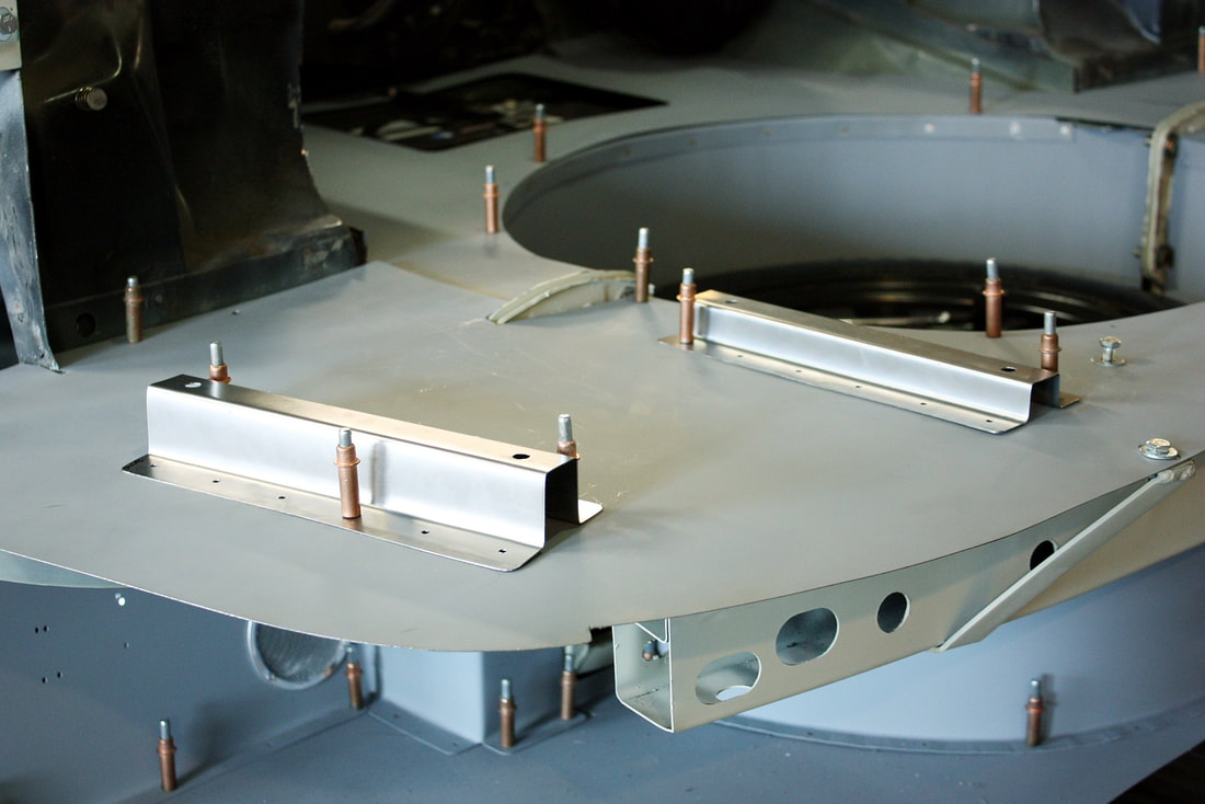
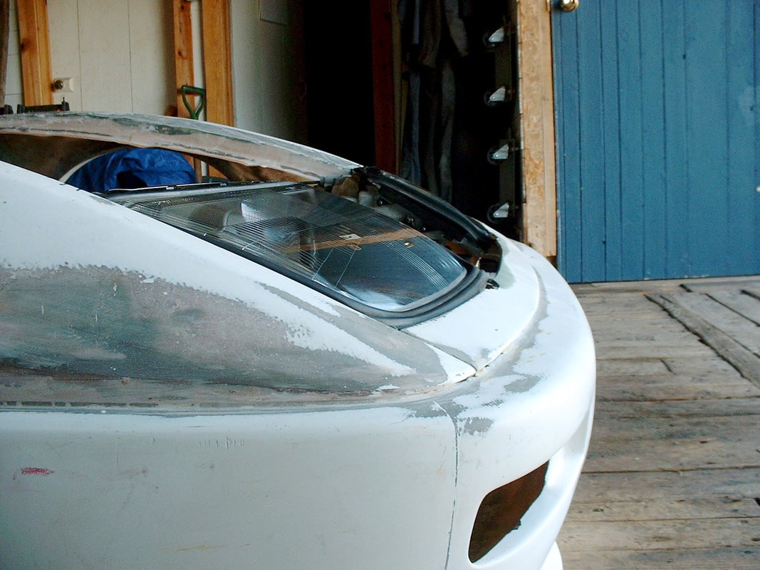
Once the steel mounts were locked into position, I reinstalled the headlights without any body work to double check that everything was still in alignment:
And finally, I reinstalled the fenders to double check the fitment with the bodywork:
Notice I’ve made a couple cardboard templates and stuck them on the fenders to round out the fibreglass corners around the lights.
The money shot:
Next up, a little lesson in JDM headlights worth heeding…

 RSS Feed
