Welcome to the Front End! In this section I'll cover the development of changes to the front suspension to make the wheels sit correctly in the wheel wells, while designing a better performing front suspension to boot.
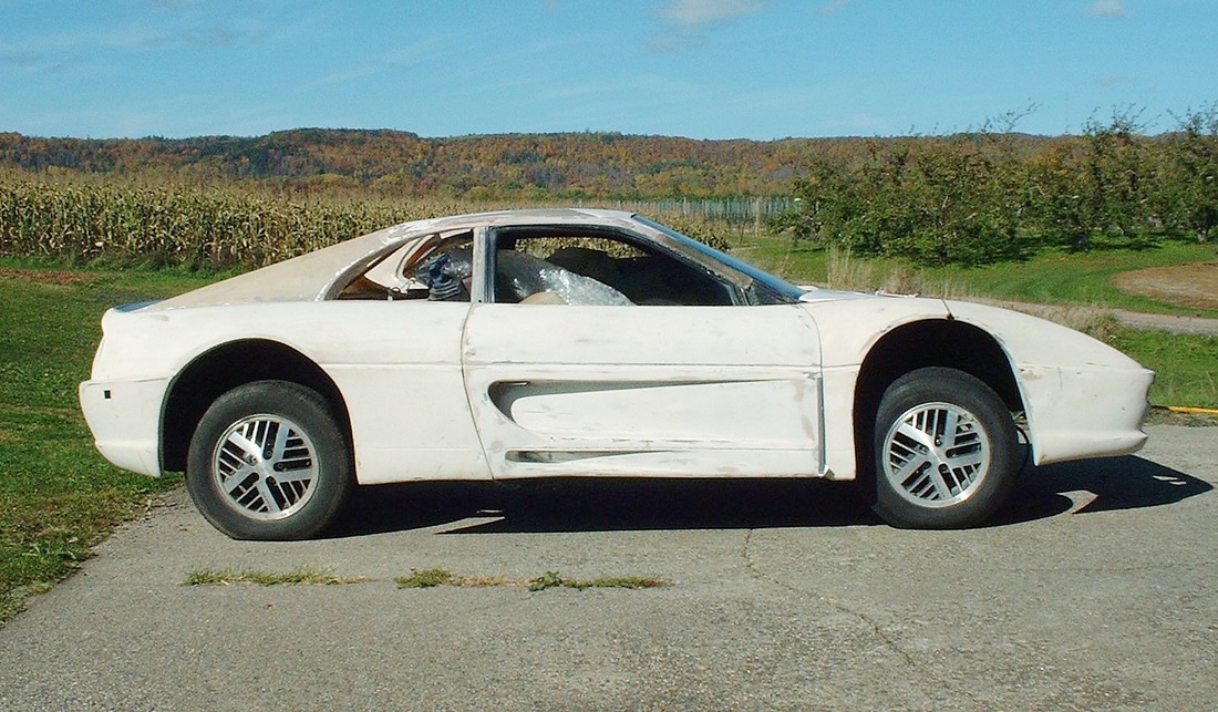
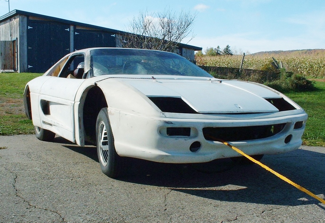
Much like with the rear end, the front end of the F355 fiberglass kit from IFG creates a ridiculous vertical gap between the fender lip and the top of the tire. The IFG fenders are of course 3" wider than the stock Fiero fenders, but the vertical wheel gap along with the asymmetry between the left and right fenders is simply inexcusable given the cost of the kit. Here's a couple of photos I've already shown but are worth posting again to show just how terrible the front proportions are:
Moving the wheels outboard, lowering the car, maintaining a reasonable ground clearance, and improving the suspension geometry was an iterative process just as with the rear end. To help guide my decisions and establish baseline data against which to make performance comparisons, I started by drawing out the all-important stock Fiero suspension and key chassis members. Here's the stock front cross member for the '88 Fiero created after some 50 hours of painstaking measurement-taking and electronic drafting:
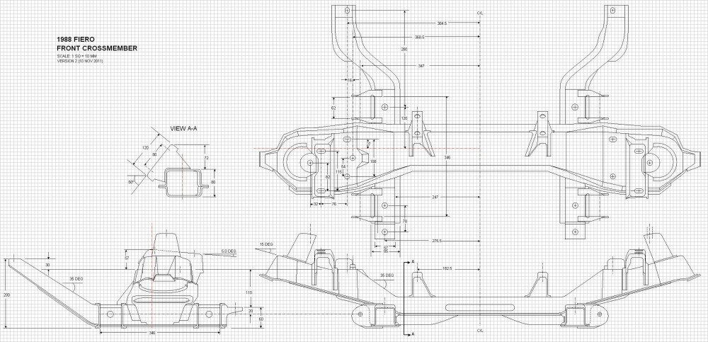
For the performance analysis, I really only needed to measure the locations of each of the pivot points in relation to each other. I hadn't needed to draw out the stock components in the detail that I did, but these drawings will make great reference material in the future when I eventually have the car inspected for certification.
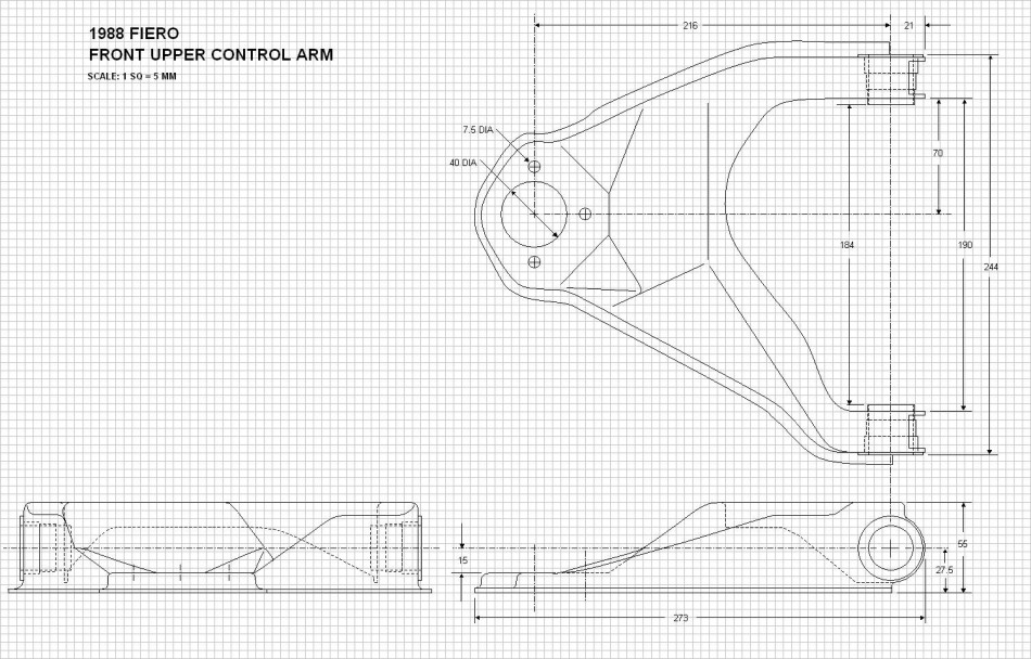
Following the cross member work, I created drawings for the stock stamped steel upper control arms...
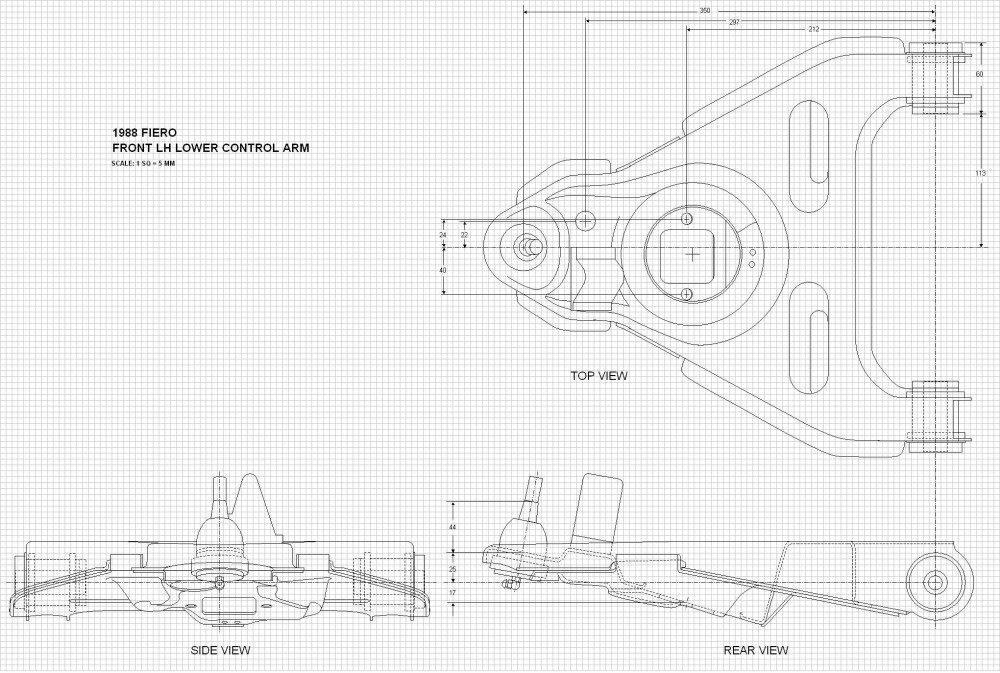
...and the lower control arms...
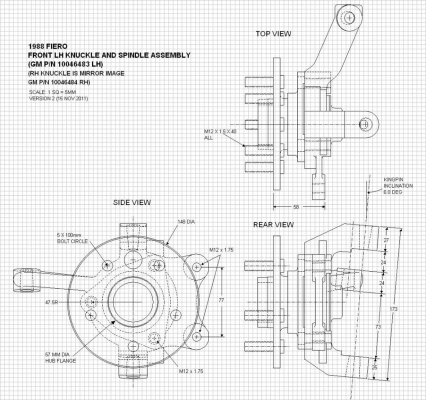
...and the cast iron knuckle along with the '88 bearing assembly:
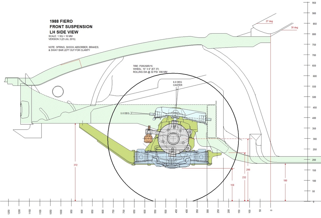
After drawing a few ancillary pieces such as the steering tie rods and ball joints, I was finally ready to combine all the pieces into a single set of front suspension drawings. Here is the side view along with some key elements of the chassis to situate the assembly:
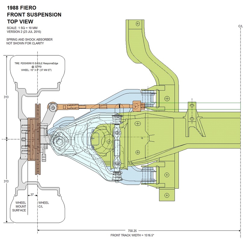
This is the simplified top view of the cross member and suspension only:
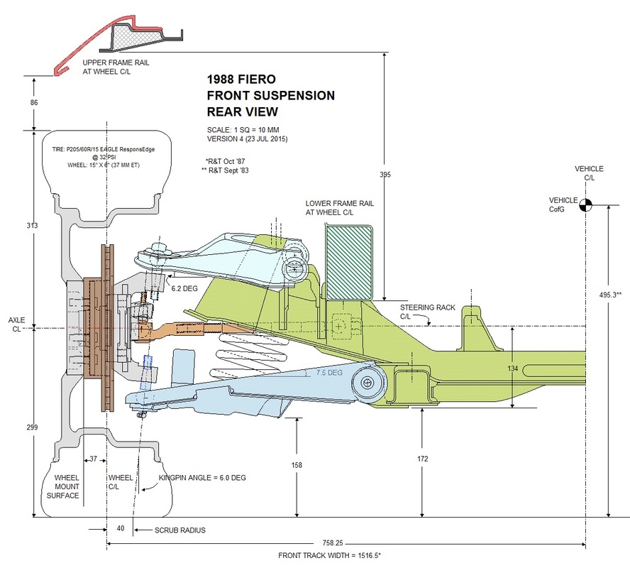
And finally, here is the rear view which I'll be using for the most part to show the progression of modifications in a similar manner that I did with the rear suspension:
With the stock drawings complete, I was able to tabulate the coordinates of the main suspension pivot points in 3D and run the simulation software to map out the stock kinematics. I'll save those graphs for later and overlay them with the kinematics of the modified front suspension to show the difference. Next up, though, is an illustrated series of progressive modifications to move the wheels out and up.

 RSS Feed
