The last couple posts have been about fabricating modified roof and sail panels and fitting them to each other. This next post is about what I needed to do to get the sail panels to sit properly on the rear quarters.
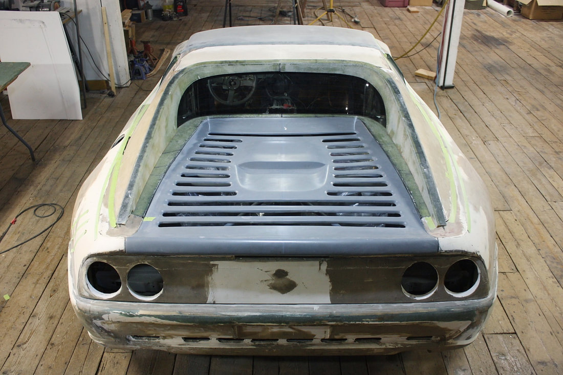
In the very beginning, I started out with rear quarters designed for a coupe, but then bought a second body which had been designed for a convertible. The convertible body had been significantly improved upon in many areas so I decided to use it instead, and convert it into a coupe by mounting the roof and sails from the first body. The trade off was that I’d have to work some magic on the convertible rear quarters since the coupe sails wouldn’t fit properly over the abbreviated convertible sails. This photo goes back several years but shows what I was dealing with:
The last couple posts have been about fabricating modified roof and sail panels and fitting them to each other. This next post is about what I needed to do to get the sail panels to sit properly on the rear quarters.
In the very beginning, I started out with rear quarters designed for a coupe, but then bought a second body which had been designed for a convertible. The convertible body had been significantly improved upon in many areas so I decided to use it instead, and convert it into a coupe by mounting the roof and sails from the first body. The trade off was that I’d have to work some magic on the convertible rear quarters since the coupe sails wouldn’t fit properly over the abbreviated convertible sails. This photo goes back several years but shows what I was dealing with:
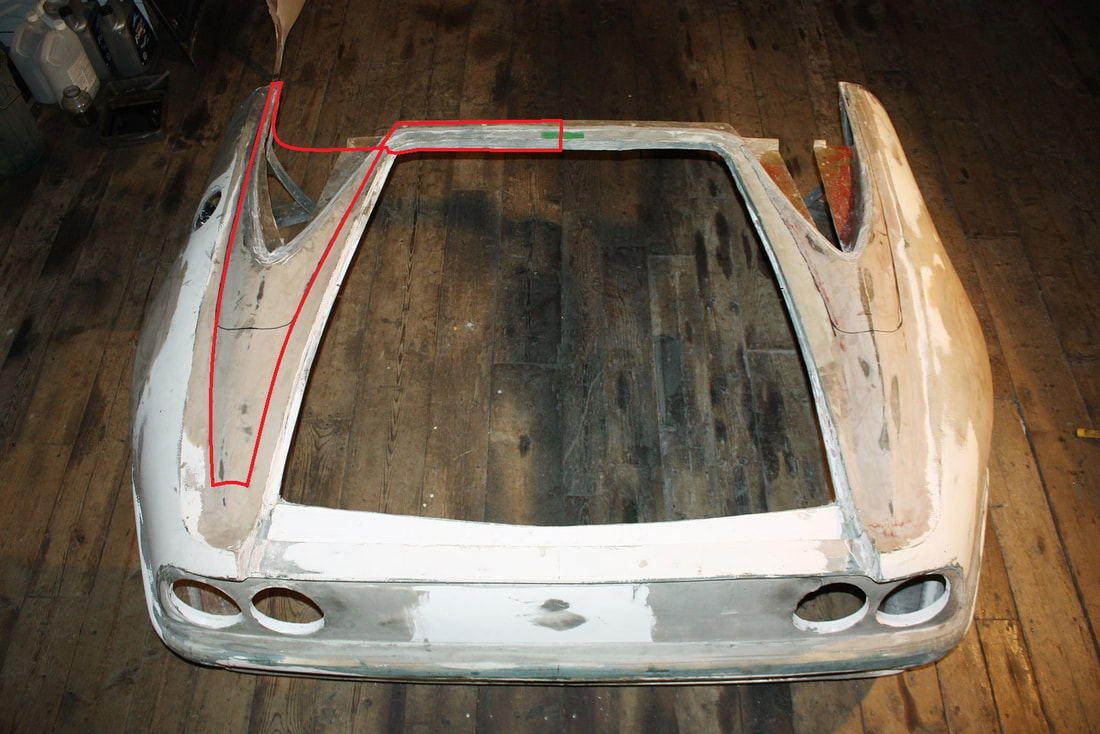
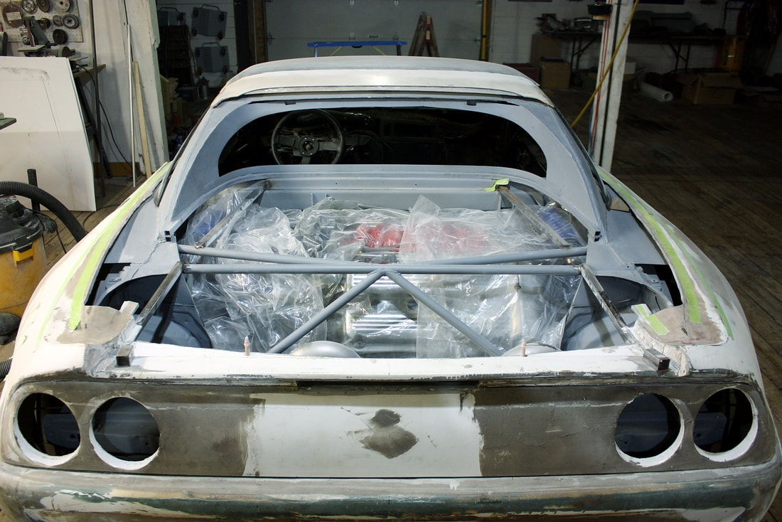
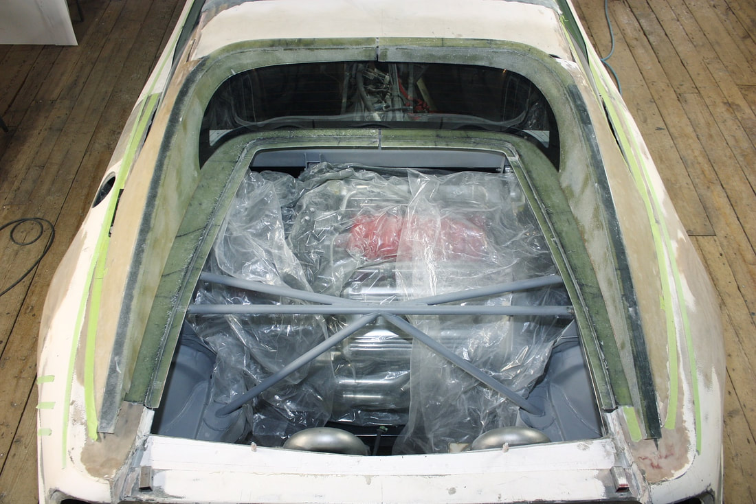
The red lines on the driver’s side show what I’ve had to chop out over several iterations and for various reasons while I’ve fitted the convertible quarters to my chassis. Here’s what I was left with once I finished chopping out the convertible’s mini sail panels:
The red lines on the driver’s side show what I’ve had to chop out over several iterations and for various reasons while I’ve fitted the convertible quarters to my chassis. Here’s what I was left with once I finished chopping out the convertible’s mini sail panels:
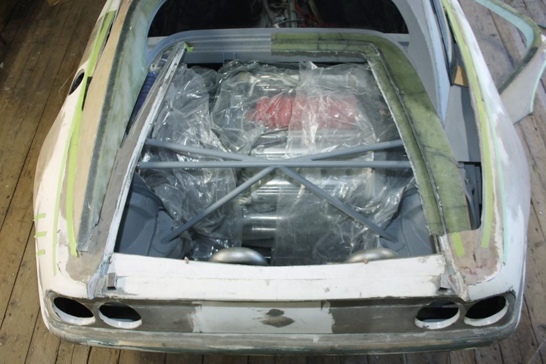
The fibreglass surrounding the decklid opening was reduced to two independent spear-like projections. They needed to be reconnected across the base of the rear window to draw the two sides together since they sprang apart when the original crossbar was removed. They also had to be lifted at the forward edge for the same reason.
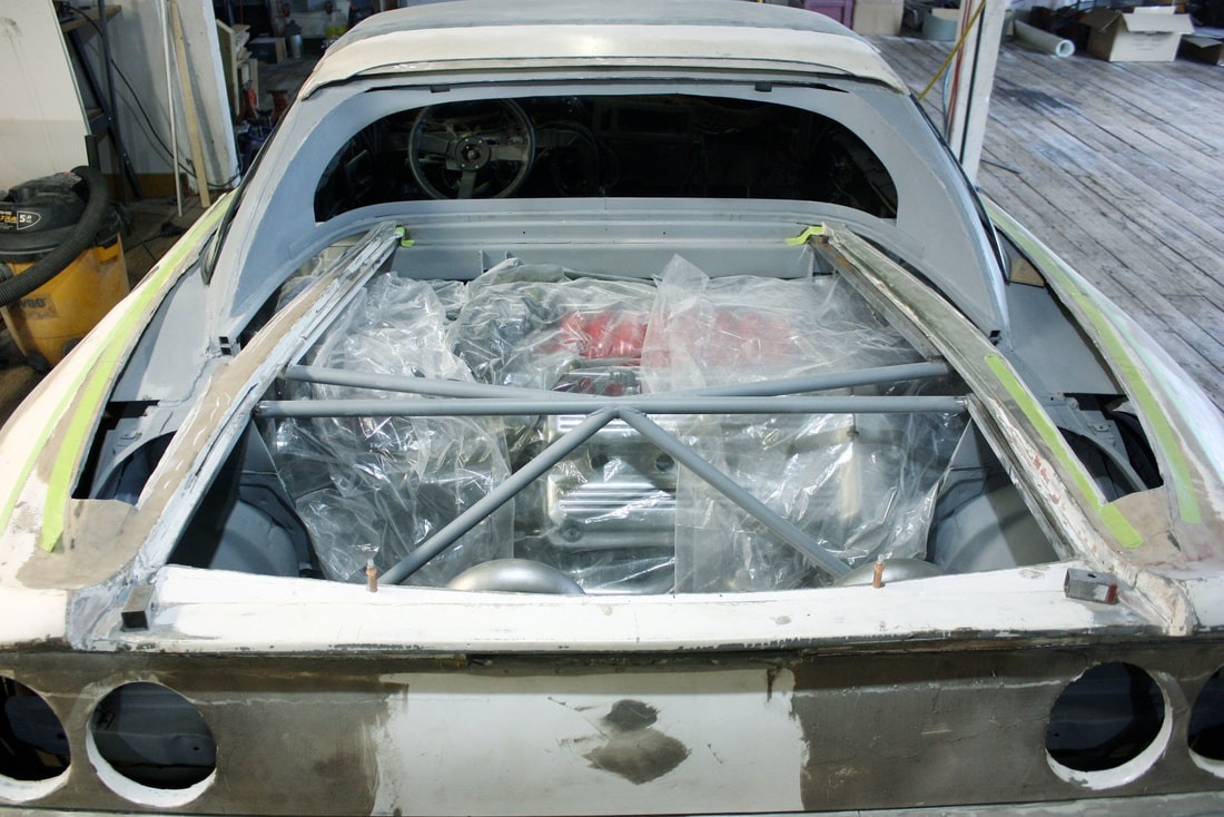
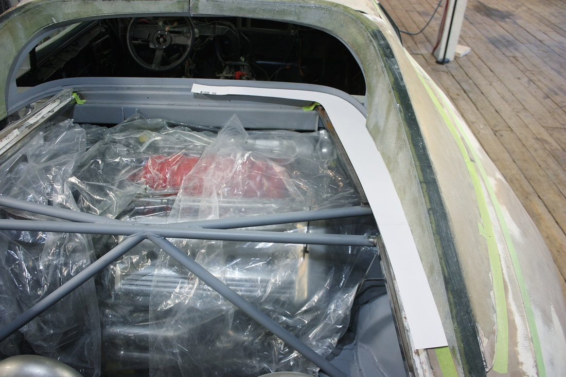
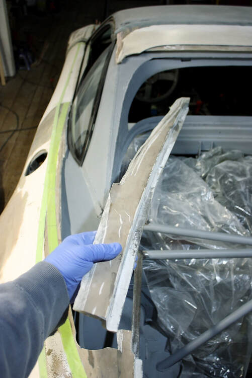
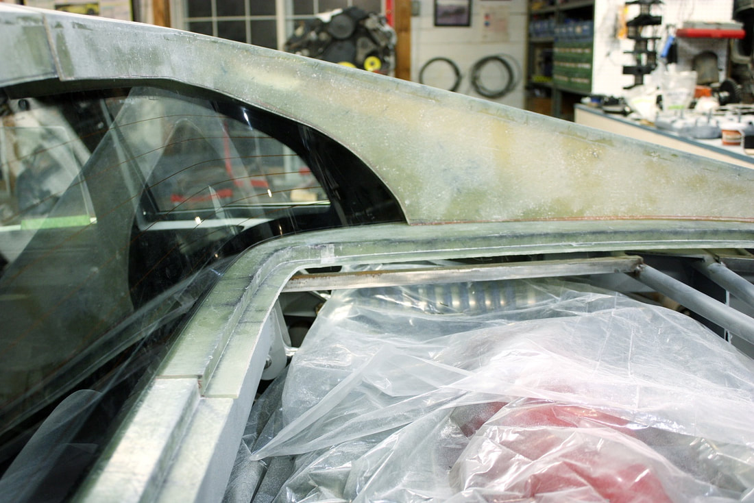
But there were other problems too. In the photo below, notice the large gap between the fibreglass decklid surround and the base of my metal sails. This gap was created when I chopped the convertible’s sails off flush with the top of the surround. So it too would need filling.
The fibreglass surrounding the decklid opening was reduced to two independent spear-like projections. They needed to be reconnected across the base of the rear window to draw the two sides together since they sprang apart when the original crossbar was removed. They also had to be lifted at the forward edge for the same reason.
But there were other problems too. In the photo below, notice the large gap between the fibreglass decklid surround and the base of my metal sails. This gap was created when I chopped the convertible’s sails off flush with the top of the surround. So it too would need filling.
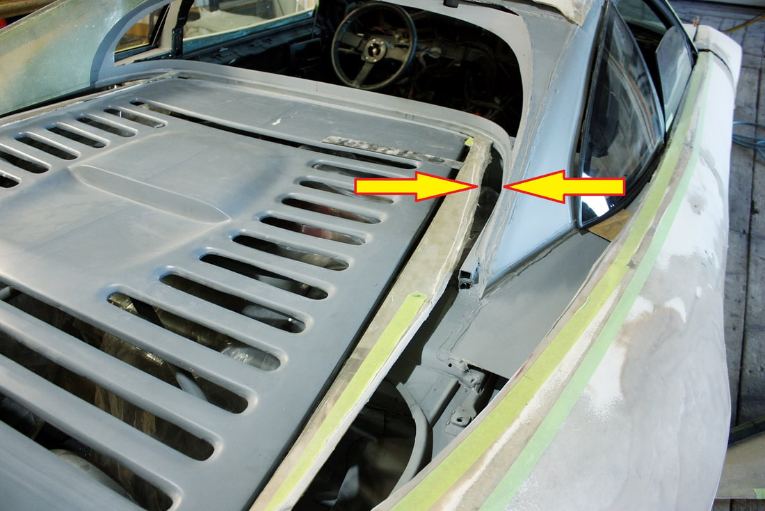
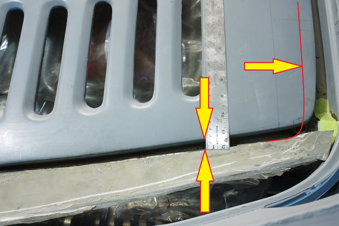
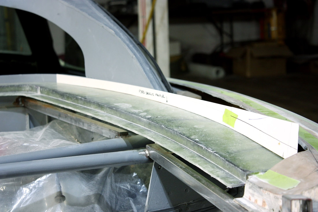
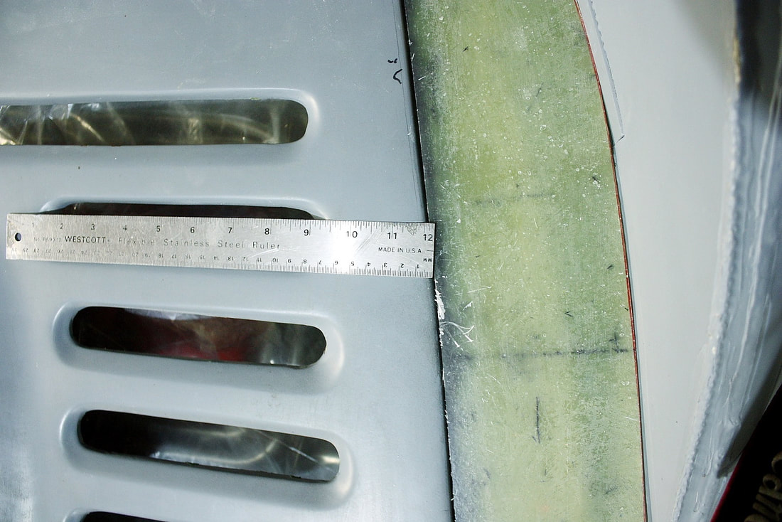
The top view of the same area shows why I needed to cut out the front portion of the surround. It used to follow the red line making the decklid opening far too short for the decklid itself. Perhaps the convertible's decklid was also shorter to compensate for the room necessary for the folded top.
It also shows by how much the sides of the surround sprang apart when I cut out the front crossbar. With the decklid centered on the chassis, the gap between the sides of the decklid and the surround was a whopping 15mm.
Given the ill-fitting nature of the IFG decklid surround, I decided it would be cleaner and likely easier to replace it rather than repair it. Recall that this area not only had to fit the decklid properly, but also provide the mounting base for the inner sail panel walls, and the rear window lower trim piece.
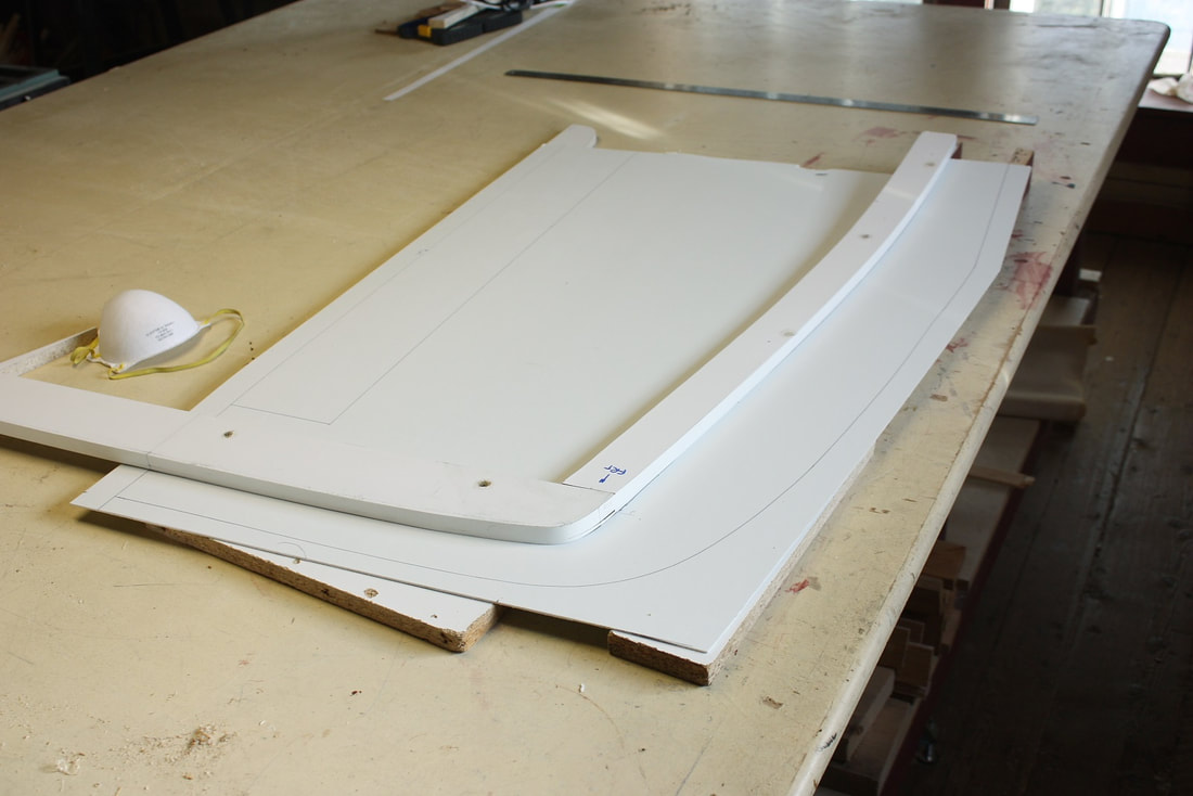
I decided to leave the old surround temporarily in place to help support the various templates I’d need to make to replace it. I started by creating a top-view template to properly index the curvature around the base of the window, to the curvature of the decklid, and to the base of the inner sail panel wall:
Given the ill-fitting nature of the IFG decklid surround, I decided it would be cleaner and likely easier to replace it rather than repair it. Recall that this area not only had to fit the decklid properly, but also provide the mounting base for the inner sail panel walls, and the rear window lower trim piece.
I decided to leave the old surround temporarily in place to help support the various templates I’d need to make to replace it. I started by creating a top-view template to properly index the curvature around the base of the window, to the curvature of the decklid, and to the base of the inner sail panel wall:
I also made a profile template of the outer decklid skin to capture the gentle convex nature of the decklid surface.
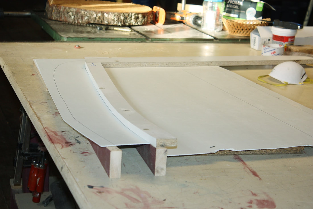
Then I used the first template to cut some 3/16” thick fibreglass reinforced plastic (FRP) shower paneling to form the base of a new mold, and some 5/8” thick melamine covered particle board to form the return flange portion of the mold. I also used some iron-on melamine tape to finish the cut edges of the melamine particle board.
I also made a profile template of the outer decklid skin to capture the gentle convex nature of the decklid surface.
Then I used the first template to cut some 3/16” thick fibreglass reinforced plastic (FRP) shower paneling to form the base of a new mold, and some 5/8” thick melamine covered particle board to form the return flange portion of the mold. I also used some iron-on melamine tape to finish the cut edges of the melamine particle board.
Next, I used the profile template to make a few wooden ribs to fasten the FRP and melamine together and to hold them to the correct curvature of the decklid skin:
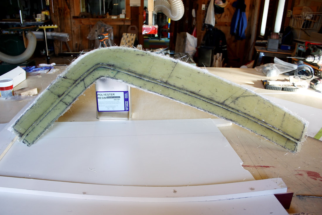
Leaving generous margins, I then waxed the mold, cut 4 layers of 1.5 oz mat, and laid up the passenger side surround with polyester resin. Note that I integrated the wrap-around front crossbar into the piece. This will remake the surface between the front of the decklid and the rear window:
Leaving generous margins, I then waxed the mold, cut 4 layers of 1.5 oz mat, and laid up the passenger side surround with polyester resin. Note that I integrated the wrap-around front crossbar into the piece. This will remake the surface between the front of the decklid and the rear window:
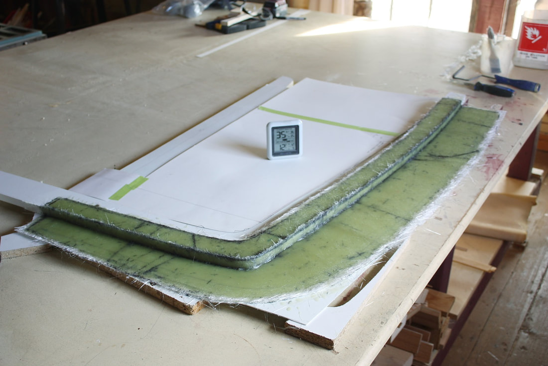
I let the resin cure for 24 hours at about 18 degrees C before popping the piece off my makeshift mold:
I let the resin cure for 24 hours at about 18 degrees C before popping the piece off my makeshift mold:
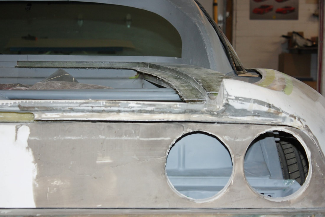
Then I used my cardboard template once again to mark the outer perimeter and cut off the excess fibreglass. I test fitted it to the chassis several times shaving a little more here and there to get it to fit as precisely as possible. At this point I was laying it on top of the old IFG surround to gauge my success with the mold. It rested perfectly on top of the rear metal window ledge and followed the same 1” x 1” square tubing toward the rear:
Then I used my cardboard template once again to mark the outer perimeter and cut off the excess fibreglass. I test fitted it to the chassis several times shaving a little more here and there to get it to fit as precisely as possible. At this point I was laying it on top of the old IFG surround to gauge my success with the mold. It rested perfectly on top of the rear metal window ledge and followed the same 1” x 1” square tubing toward the rear:
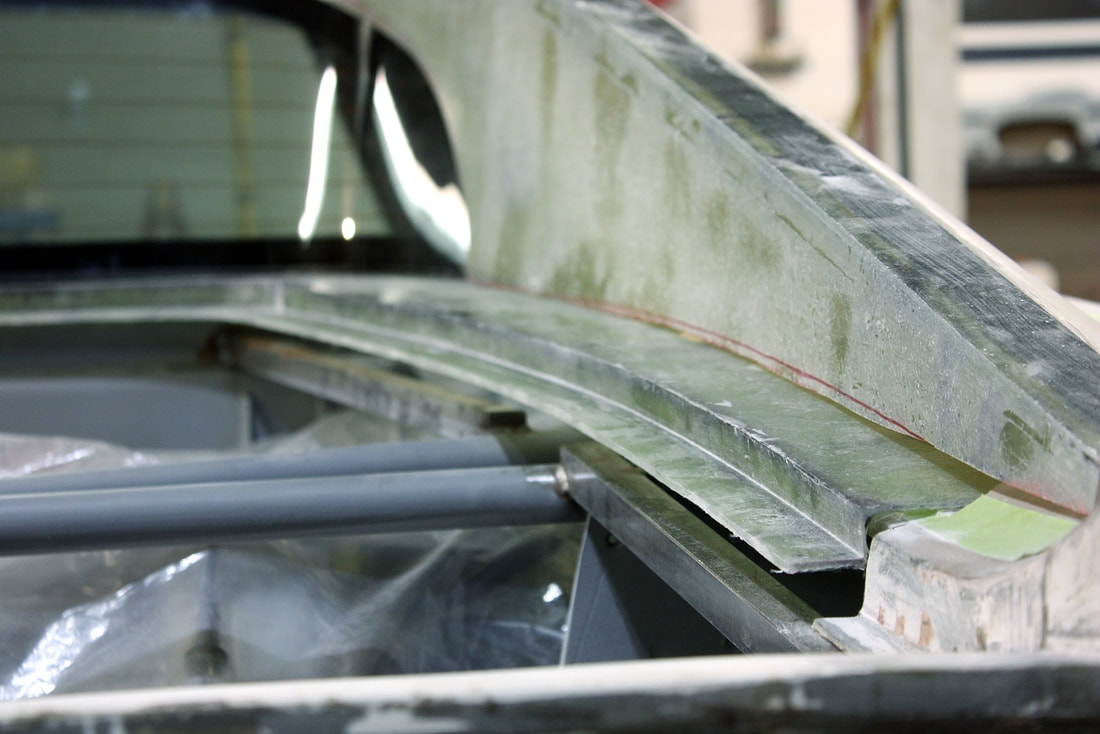
Here’s a low angle photo from the rear showing the compound curve of the decklid surround. At this point the return flange still had to be trimmed:
Here’s a low angle photo from the rear showing the compound curve of the decklid surround. At this point the return flange still had to be trimmed:
I was happy with the fit, so I proceeded to slice off the old IFG surround being confident that my solution to replace the part would work. I used a thin cut-off wheel in my angle grinder to make quick work of the dirty task:
I was happy with the fit, so I proceeded to slice off the old IFG surround being confident that my solution to replace the part would work. I used a thin cut-off wheel in my angle grinder to make quick work of the dirty task:
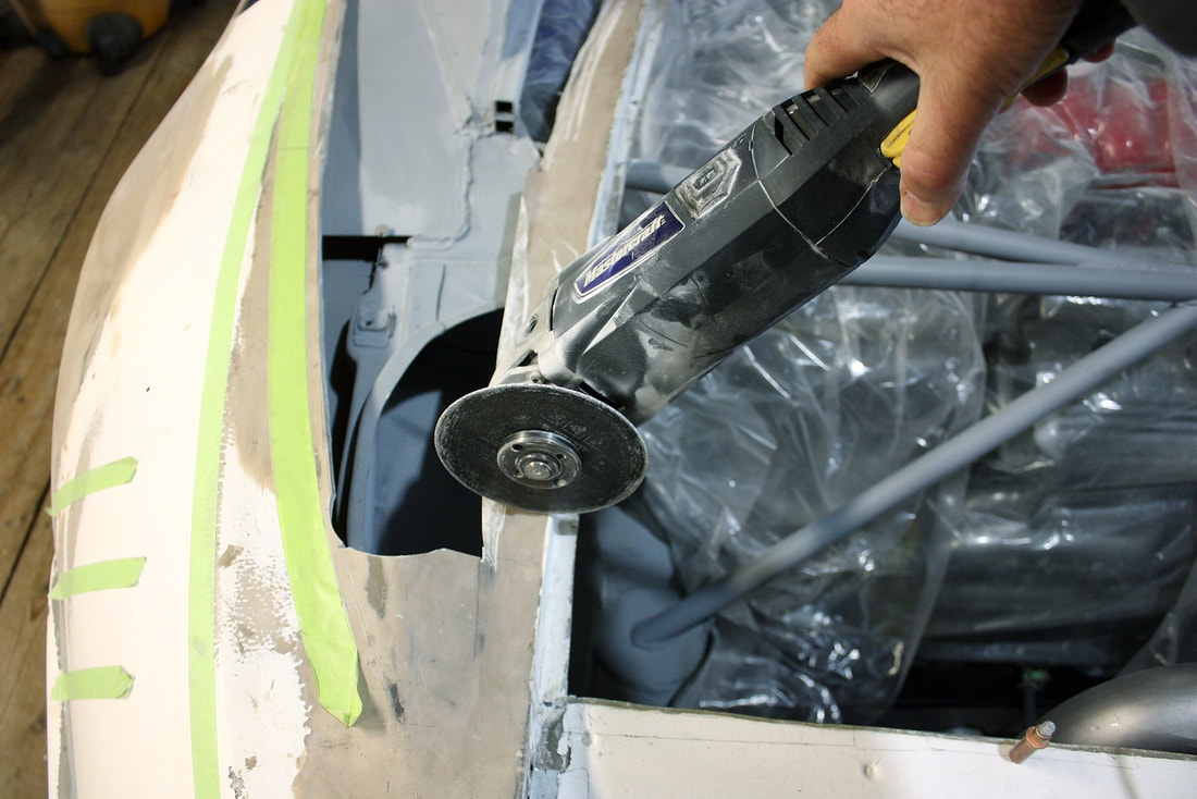
Thinking ahead, I decided not to cut the old surrounds off flush, rather, leaving a pair of stubs to support the rear edge of my new panel to eventually use them as bonding points:
Thinking ahead, I decided not to cut the old surrounds off flush, rather, leaving a pair of stubs to support the rear edge of my new panel to eventually use them as bonding points:
Refitting the new decklid surround, I double-checked the correct curvature with the cardboard profile template I had made earlier:
Refitting the new decklid surround, I double-checked the correct curvature with the cardboard profile template I had made earlier:
I then used the profile template to transfer the curvature to the bottom edge of the inner sail panel wall:
I then used the profile template to transfer the curvature to the bottom edge of the inner sail panel wall:
It took several iterations of trimming and checking the fit since each time I trimmed the lower edge of the sail panel, it would sit lower and change the orientation of the fit at the roof. Definitely a case of measure many times, trim many times!:
It took several iterations of trimming and checking the fit since each time I trimmed the lower edge of the sail panel, it would sit lower and change the orientation of the fit at the roof. Definitely a case of measure many times, trim many times!:
With the passenger side turning out so well, I disassembled the mold for the surround, and rebuilt the mirror image of it to lay up the driver’s side piece. Going through all the same steps, I popped out, trimmed, and fitted another surround in about half the time it took to make the first:
With the passenger side turning out so well, I disassembled the mold for the surround, and rebuilt the mirror image of it to lay up the driver’s side piece. Going through all the same steps, I popped out, trimmed, and fitted another surround in about half the time it took to make the first:
To properly fit both halves of the surrounds, I had to trim enough fibreglass from their outer perimeters to get them to fit in the space between the two metal sail panels. Of course the more I trimmed off of the outer edges of the fibreglass pieces, the further they would end up from each other, widening the opening for the decklid as a consequence. Obviously there was an exact amount of fibreglass I needed to trim off the perimeter of each surround such that they would fit perfectly between the metal sails, and also result in a tight fitting decklid:
To properly fit both halves of the surrounds, I had to trim enough fibreglass from their outer perimeters to get them to fit in the space between the two metal sail panels. Of course the more I trimmed off of the outer edges of the fibreglass pieces, the further they would end up from each other, widening the opening for the decklid as a consequence. Obviously there was an exact amount of fibreglass I needed to trim off the perimeter of each surround such that they would fit perfectly between the metal sails, and also result in a tight fitting decklid:
Initially when I went to mock up the decklid, the width of the decklid opening was too narrow. That’s what I had been hoping for. That allowed me to gradually trim the outer perimeter of both surrounds, centering them on the car, and leaving just the right amount of space between them for the decklid to fit tightly. At this point I left the gap as small as possible since I knew I would need to shave the decklid later in some areas and add filler in others to make both sides of the lid symmetrical… because of course, they weren’t.
Initially when I went to mock up the decklid, the width of the decklid opening was too narrow. That’s what I had been hoping for. That allowed me to gradually trim the outer perimeter of both surrounds, centering them on the car, and leaving just the right amount of space between them for the decklid to fit tightly. At this point I left the gap as small as possible since I knew I would need to shave the decklid later in some areas and add filler in others to make both sides of the lid symmetrical… because of course, they weren’t.
When all is said and done, I’ll be aiming for 3mm gaps.
When all is said and done, I’ll be aiming for 3mm gaps.

 RSS Feed
