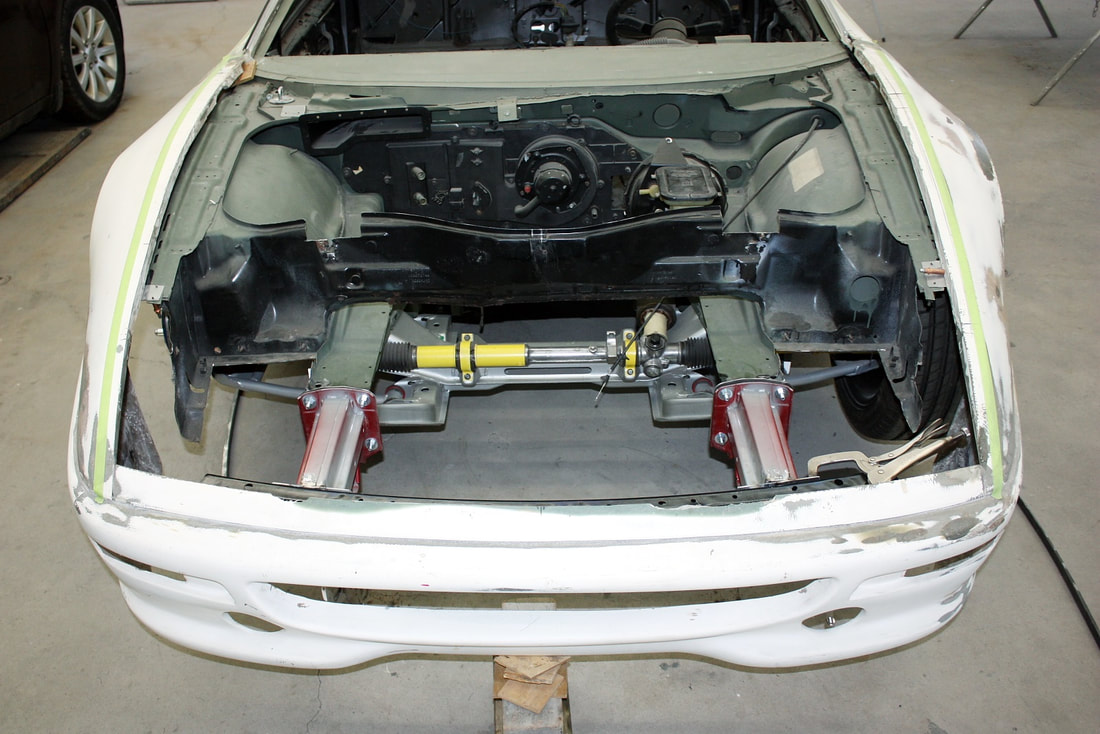
The IFG front clip is a one-piece unit that incorporates the two fenders, the front fascia, and a front trim piece just ahead of the hood. All of these are separate panels on the authentic Ferrari. Whether I separated them or not was going to be dependent on how well they aligned to each other and how well they fit the chassis. So I mocked up the front clip and started planning the mounts:
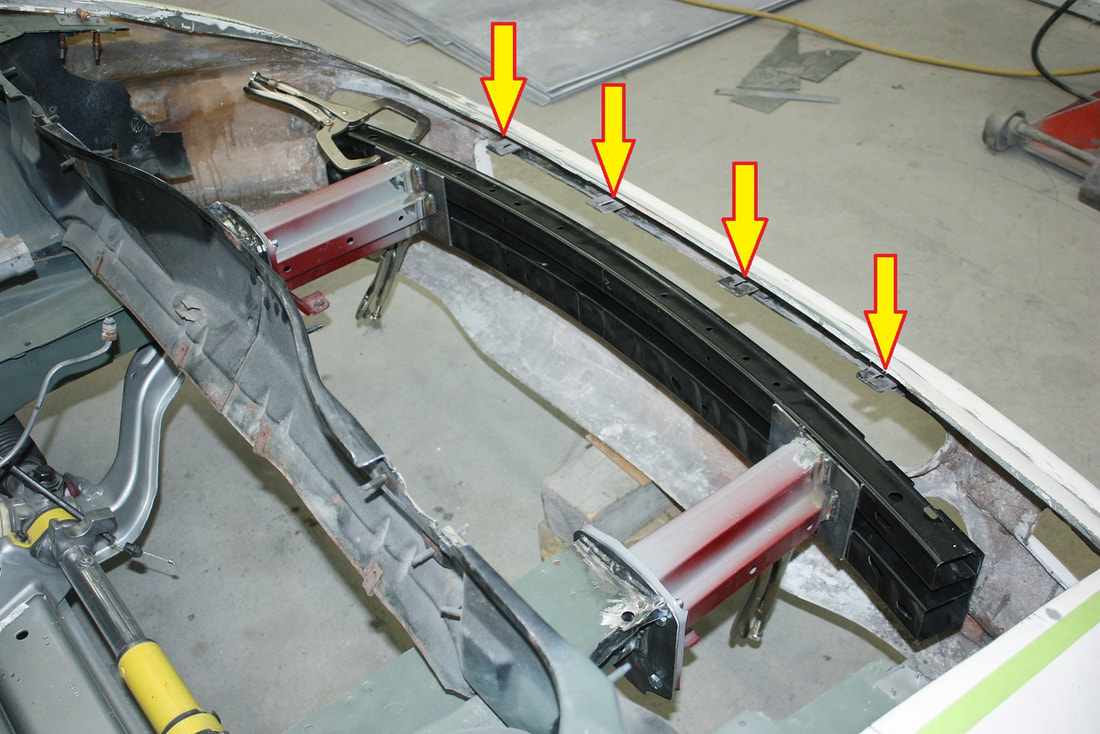
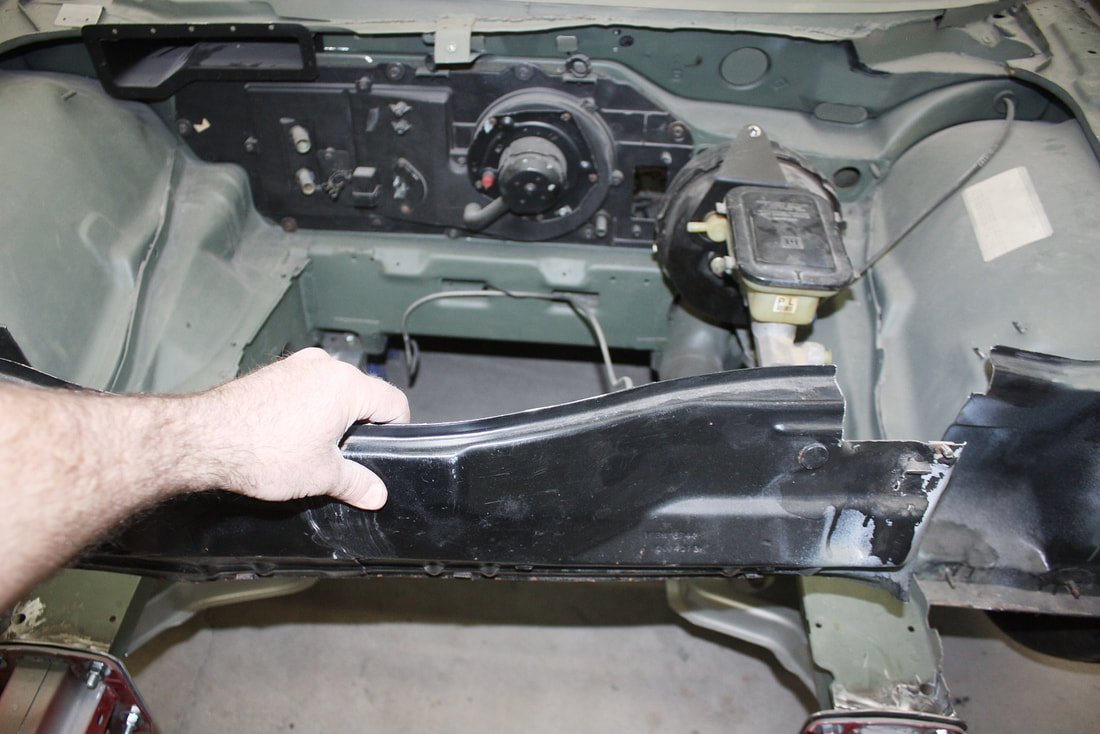
At some point in the front clip’s history, Don ‘glassed in some ¾” square steel tubing along the inside front edge of the fascia. To that, he also welded four tabs with slotted holes. Back in Post #106, I deliberately mounted the front metal bumper at a height corresponding to these tabs to simplify designing the front fascia support:
Here’s the plan to connect these tabs to the chassis:
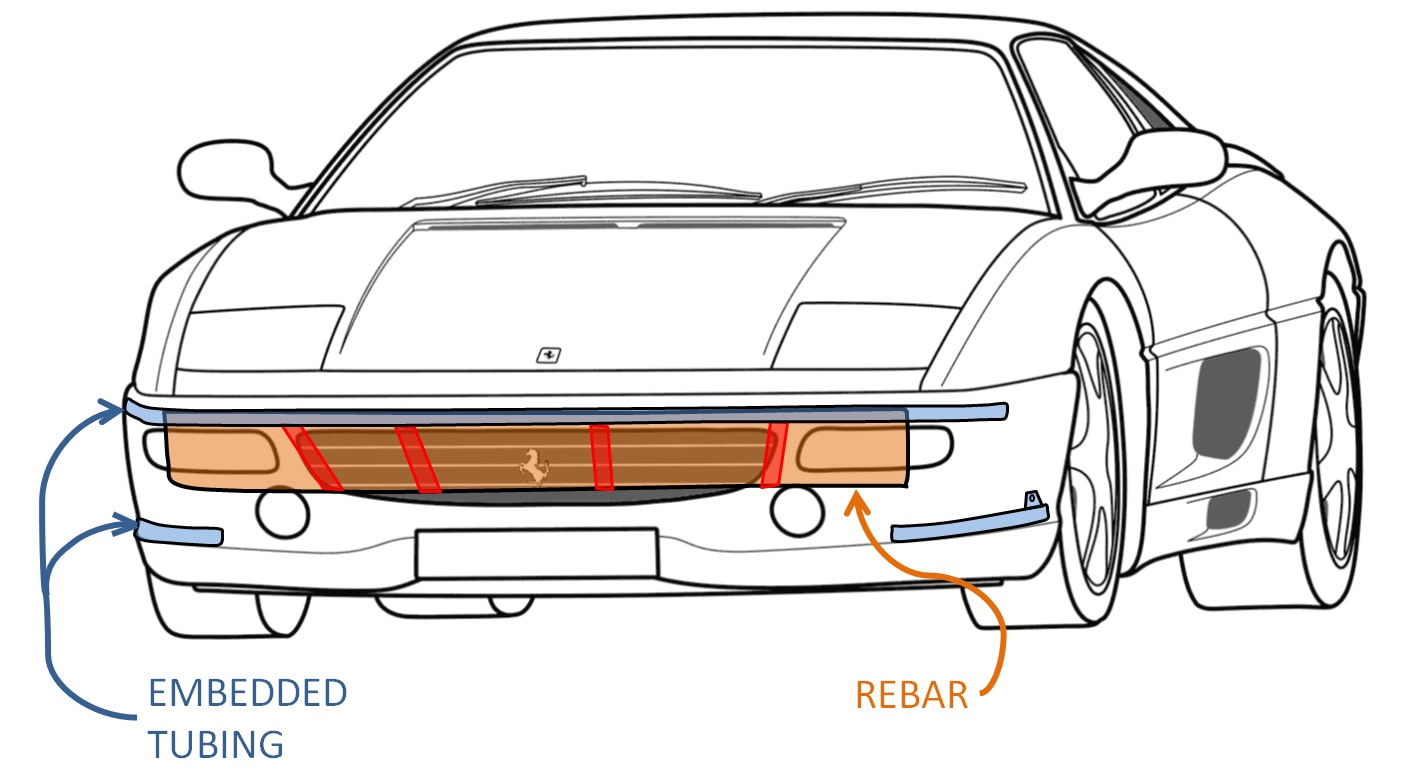
The blue represents the ¾” square tubing embedded into the fibreglass, the orange is the metal bumper bar I installed in Post #106, and the red is the simple bracketry to bridge the upper tubing to the metal bumper. Easy-peasy.
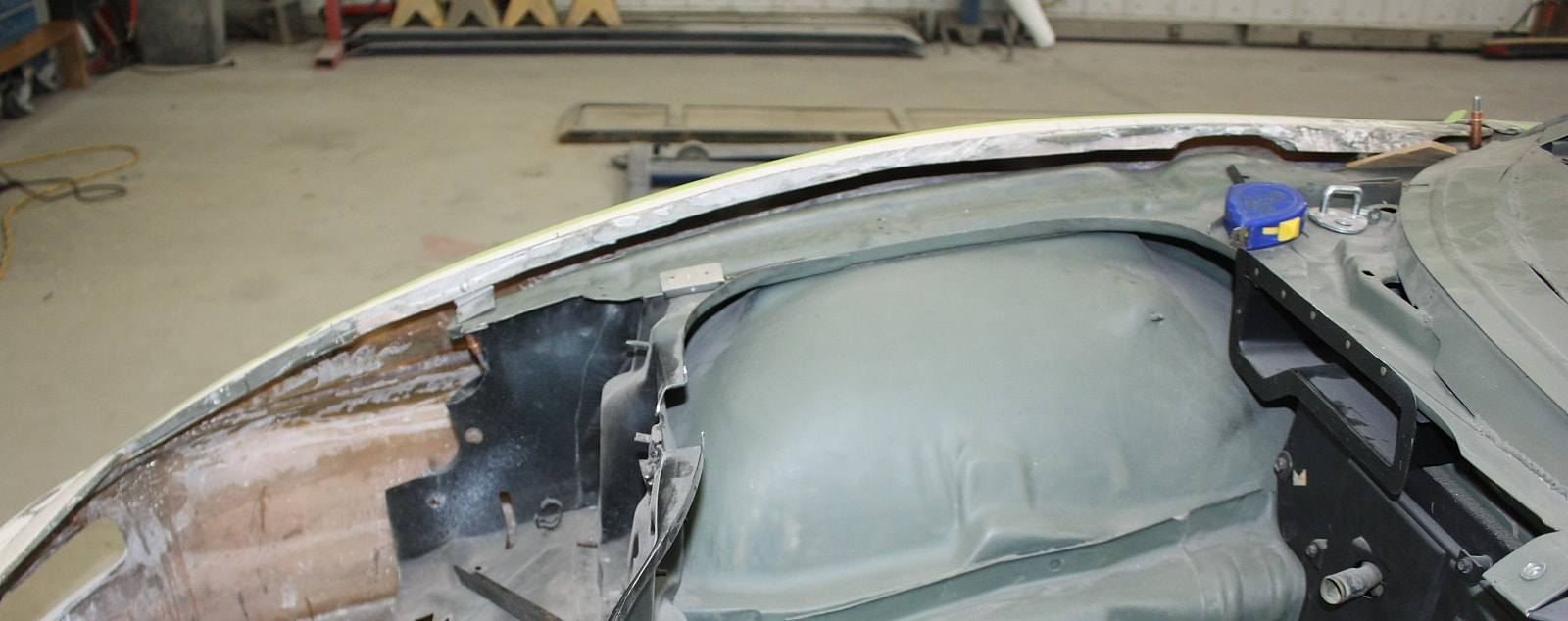
I figured I’d start with this since it would level the front clip and position it side to side and fore and aft. I’d deal with the fenders later. But first I decided to do away with the stock Fiero front compartment wall, once and for all:
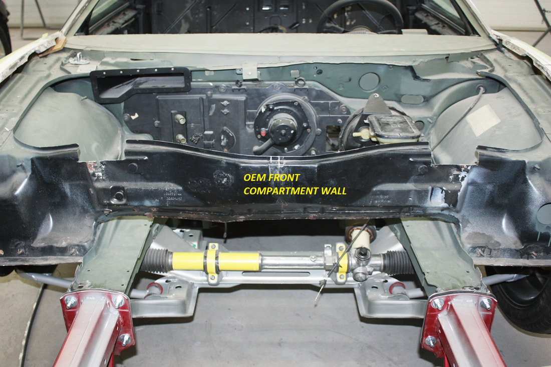
I left it in until I was sure I wouldn’t need it. It’s simply a sheet metal divider used to separate the wet radiator compartment from the dry spare tire and storage compartment. The whole area will be a dry compartment in this car, so I chopped it out:
That opened things up for me to sit in the front area and fabricate the front fascia support brackets from an easier vantage point:
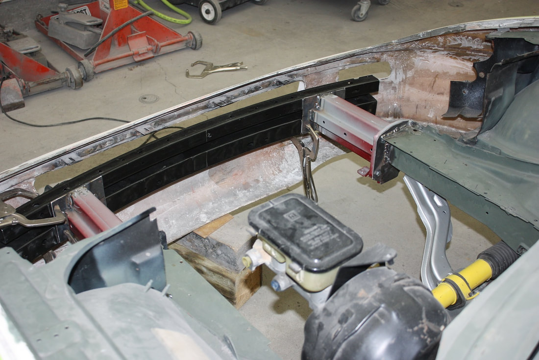
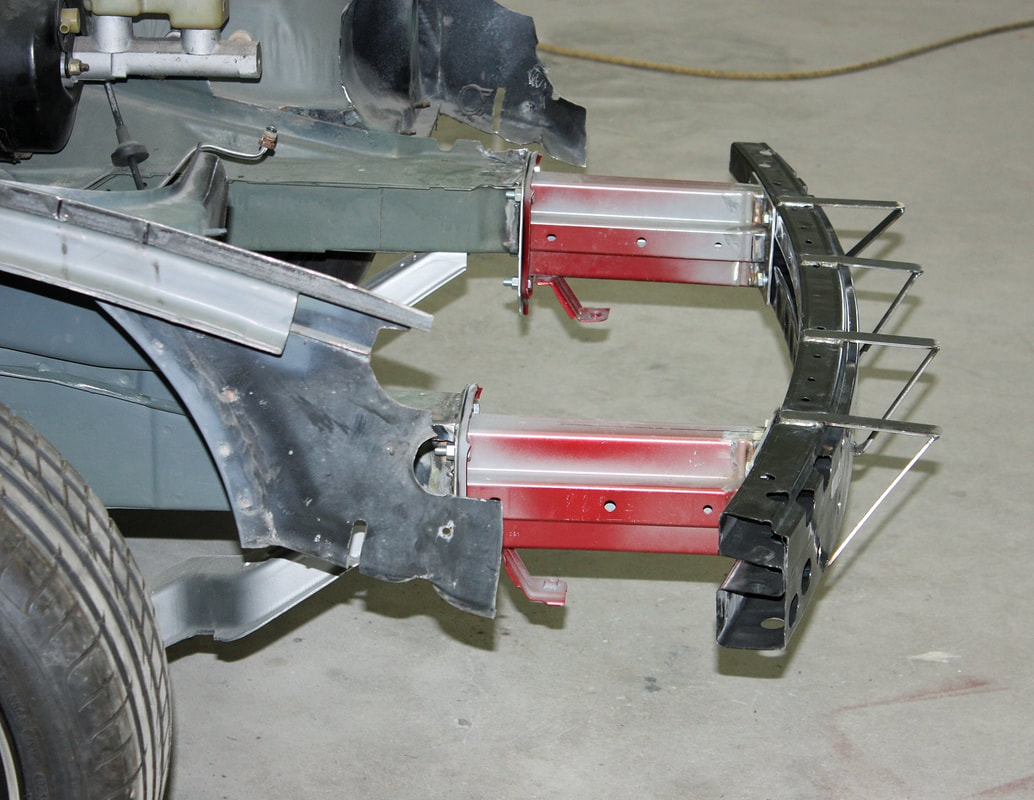
After shimming the front fascia perfectly level to the chassis, I cut some 1” x 1/8” steel strips long enough to bridge the gap between the mounting tabs and the top of the metal bumper:
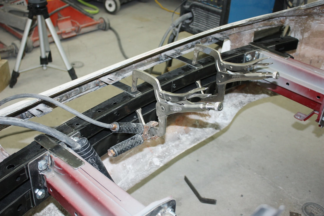
Then, I removed the front clip and triangulated the first set of strips with some diagonal braces down to the bottom edge of the bumper bar:
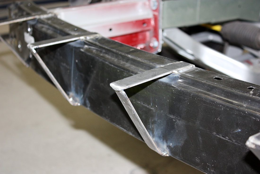
It rather looked like a cow-catcher off a train at this point. While it looks somewhat dangerous for pedestrian collisions, bear in mind that the points are shielded behind a ¾” square tube:
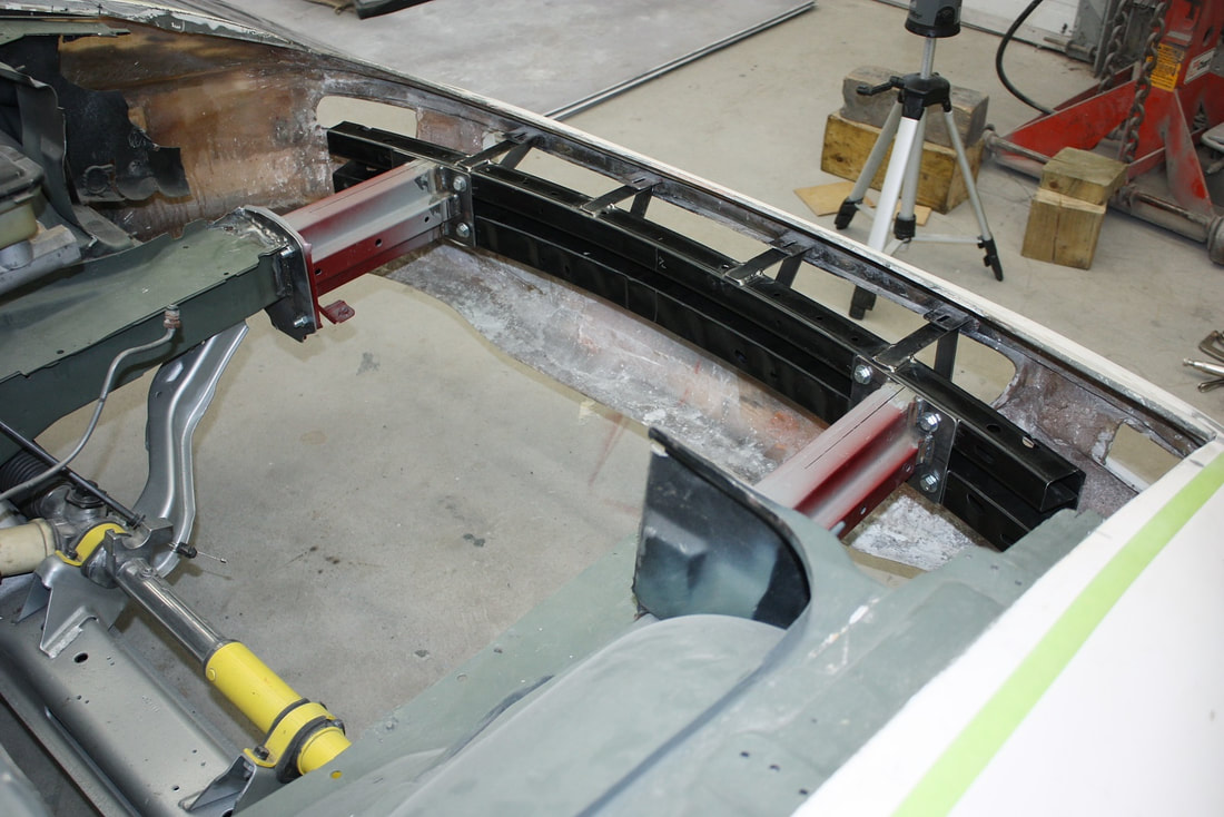
Here it is with the front clip mocked up, and supported by the new front mounts:

Next up was to mount the fenders to the upper frame rails (or what was left of them!):
Theoretically, this should’ve been a simple task: shorten the fibreglass fender mounting flanges I cut off earlier, re-bond them to the fenders, and bolt the flanges to the upper frame rail, just like the Fiero fenders.
That would’ve been fine except the IFG front clip is no different quality-wise from the rest of the panels. It’s warped, and has non-symmetrical wheel and fender arches from one side to the other. Even the width of the hood opening isn’t the same distance from either fender to the centreline. Bonding new fender flanges to this mess would’ve simply cast these defects further into stone.
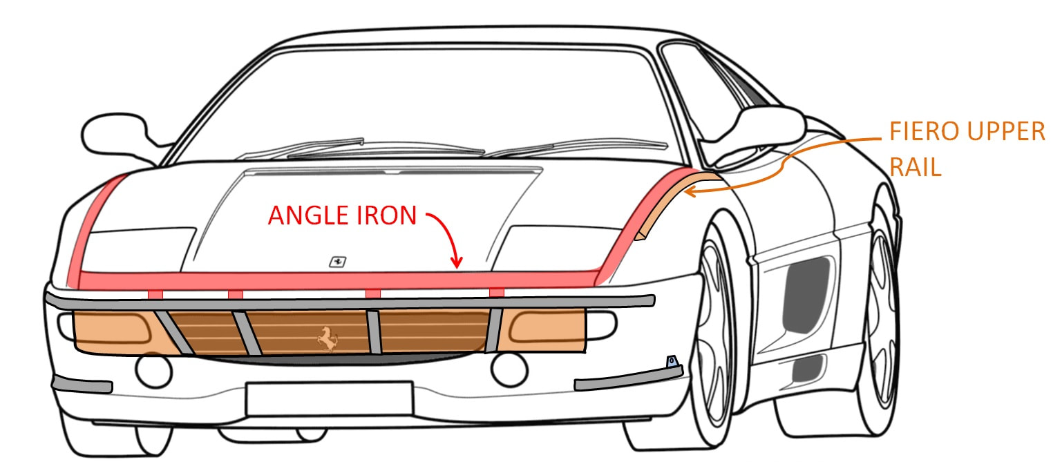
I decided instead to shape some angle iron to the arch I wanted for the fenders, and weld it to the upper rails. Then I’d modify the fibreglass to fit that arch, thereby ensuring symmetry side to side as well. Here’s the plan:
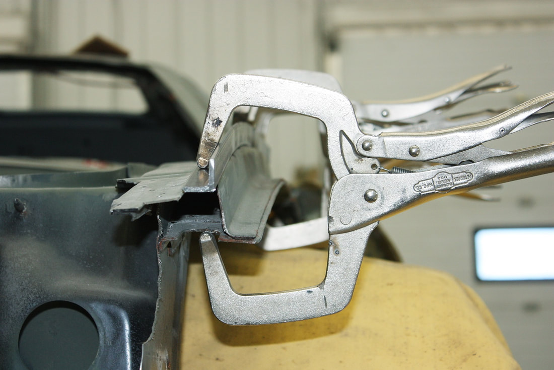
I decided to make each fender support from two long pieces of angle iron, essentially making a Z shape. This way I could form the lower piece to the shape of the frame rail, the upper piece to the fender, and weld the two together. Here’s the driver’s side lower angle iron clamped in place:
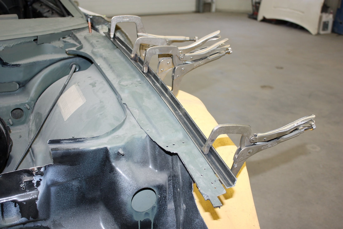
I just slit the vertical leg of the angle in multiple places, curved it to fit, and welded the slits closed:
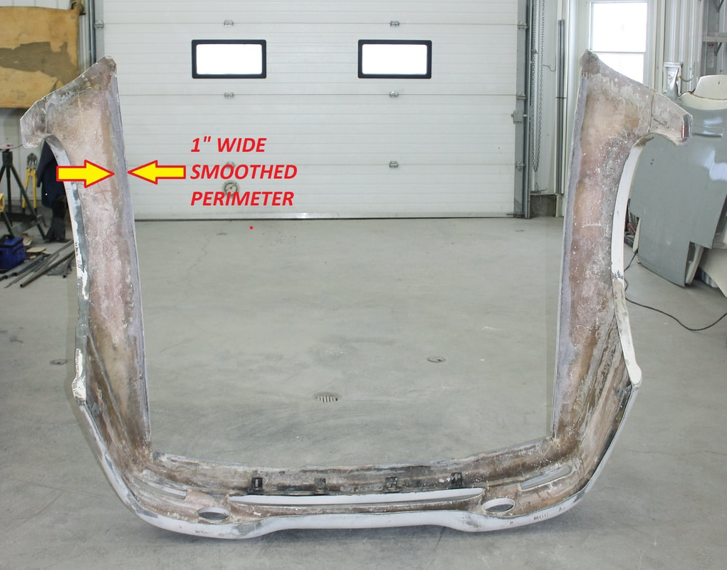
Next, I ground the perimeter area under both fibreglass fenders smooth and to a consistent thickness using an air-powered, hand held, 1” wide belt sander. I checked routinely with a set of calipers to make sure I left at least ¼” thickness.
After mocking up the fenders one more time, I found that the fibreglass fender arch on the LH side flowed nicely with the door lines, so I decided to create the upper portion of the “Z” to fit the LH fender curvature. I slit it, as I did with the lower angle, and bent it gently until it followed the inside contour of the LH fender perfectly. Then, once all the parts on the LH side were mocked up and clamped in position, I tack welded them together, and to the frame rail:

Then, I built the same pieces for the RH side, but rather than contouring them to the RH fender, I created mirror image pieces from the LH parts. The RH fender wouldn’t fit super well on these mounts since the fibreglass had a different curvature than on the LH side, but that was deliberate. The RH fender needed to be reshaped to match the LH, so having identical underlying supports was the first step to creating symmetrical fenders.
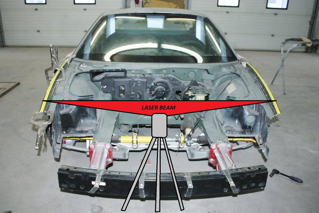
In order to ensure the RH support was mounted at exactly the same height and position as compared to the LH side, I used yellow tape with marks 1” apart all the way up both sides like this:

Then, by placing the laser level in front of the chassis, and shining the horizontal beam onto the tape, I could tell whether both sides were even or not by whether the beam intersected the tape at the same measurement points on either side:
Once I was happy both sides were properly positioned in relation to each other, I tack welded the passenger side fender supports in place, and removed the clamps.
Next up: the front corners. Stay tuned for part 2 of the front fender mounts.

 RSS Feed
