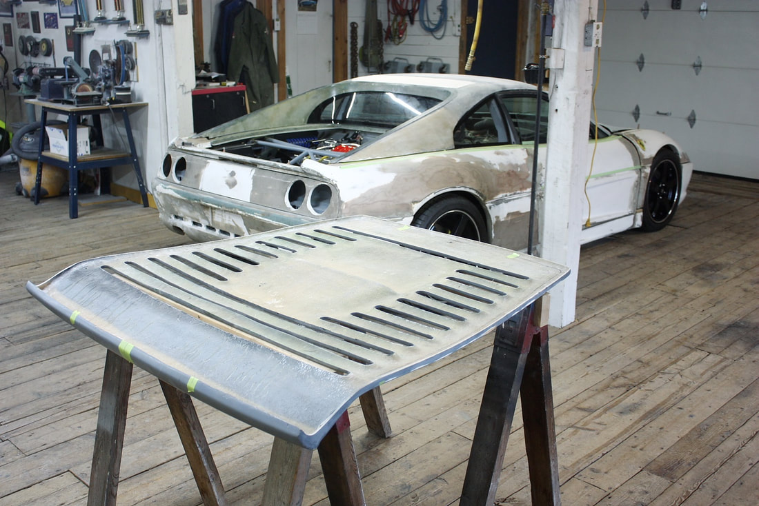
It helps to take a step back every now and then remind myself where I’m at and where I’m going. I am nearly finished the phase I set out to do more than two years ago in post #120, namely, mount the body panels to the chassis.
There have been a number of sidetracks to this process but all of them were necessary. I’m finally at the last body panel: The Deck Lid. Here it is mocked up on the chassis:
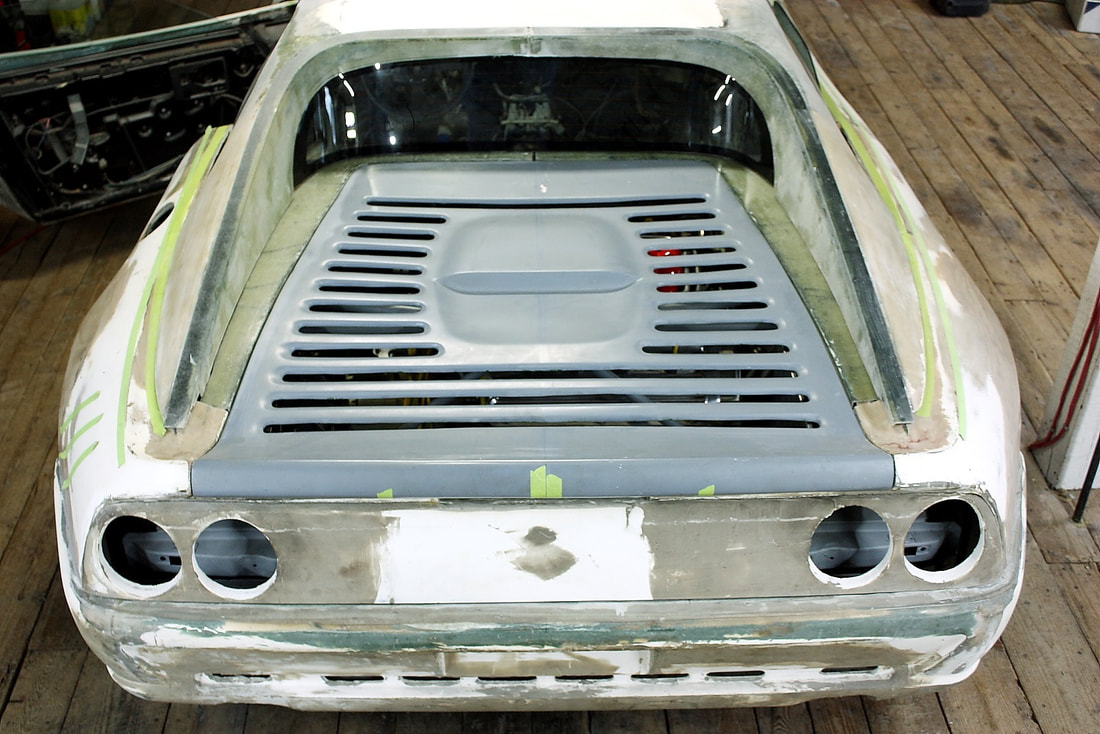
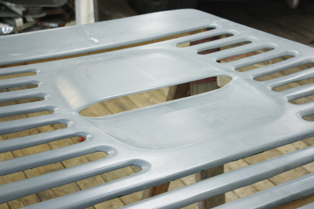
Like all the other International Fibreglass Group panels, the deck lid wasn’t close to being ready for a quick and dirty install. Cosmetically, the gill-like vent slots are all different widths, and have different radii and chamfering at each end, but more importantly the entire lid was molded with a downward sag in the middle:
Like all the other International Fibreglass Group panels, the deck lid wasn’t close to being ready for a quick and dirty install. Cosmetically, the gill-like vent slots are all different widths, and have different radii and chamfering at each end, but more importantly the entire lid was molded with a downward sag in the middle:
The return flanges along each gill-vent and the compound curvature of the center scoop conspired to stiffen the lid in the sagged position. This had to be addressed before building a structural frame for the lid to prevent the faults from being much harder to deal with later on:
The return flanges along each gill-vent and the compound curvature of the center scoop conspired to stiffen the lid in the sagged position. This had to be addressed before building a structural frame for the lid to prevent the faults from being much harder to deal with later on:
Thankfully the underside of the deck lid was surprisingly smooth, which would reduce a good chunk of work since much of underside will be exposed when the engine bay is open.
Thankfully the underside of the deck lid was surprisingly smooth, which would reduce a good chunk of work since much of underside will be exposed when the engine bay is open.
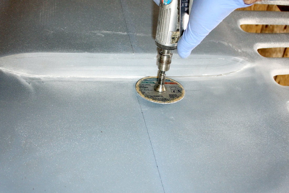
To begin ironing out the sag in the deck lid, I tried flexing the entire panel with my knee while holding both outer edges to pinpoint the areas that were resisting being straightened. It was clear right away that the un-cut engine scoop acted like a return flange, reinforcing the sag. I made quick work of the offending fibreglass with a thin cut off wheel in my die grinder:
To begin ironing out the sag in the deck lid, I tried flexing the entire panel with my knee while holding both outer edges to pinpoint the areas that were resisting being straightened. It was clear right away that the un-cut engine scoop acted like a return flange, reinforcing the sag. I made quick work of the offending fibreglass with a thin cut off wheel in my die grinder:
That step alone didn’t spring the lid entirely back to being flat, but it increased the flexibility of the lid by about 50%. For the remaining 50%, I had three choices: slit the fibreglass longitudinally down the centreline and pull both halves up and re-bond; or slit it transversely about the center and do the same; or force the lid to conformity with an underlying structure:
Cutting and rejoining the fibreglass is always my last choice because it leaves the joint vulnerable to showing up later under the paint, so I decided to give a “go” at using an underlying structure to force it flat.
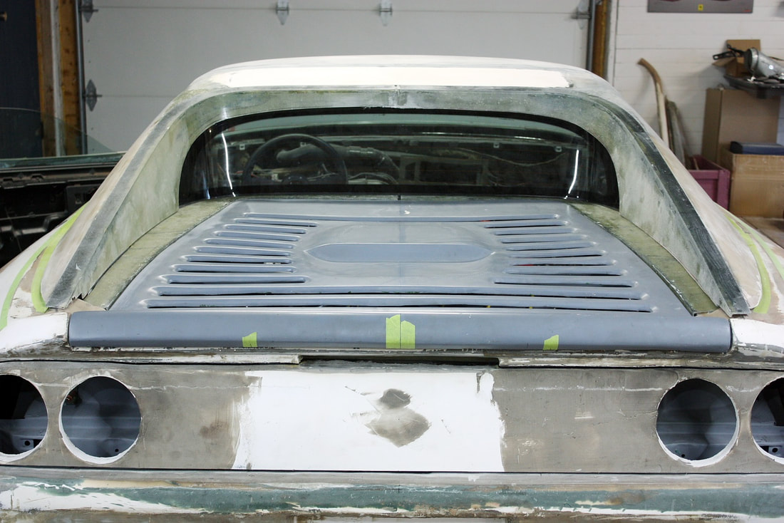
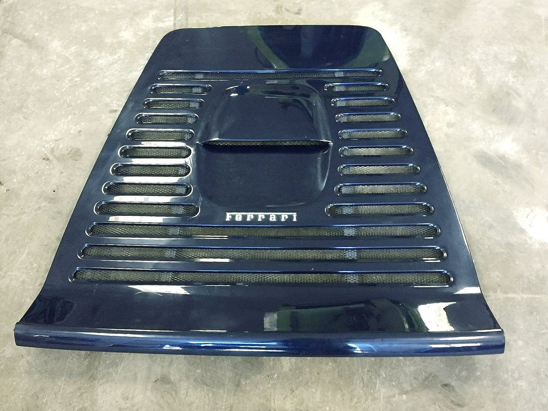
A close look at the authentic Ferrari’s deck lid led me to believe that I could probably duplicate the authentic lid’s structures to accomplish my goal. From the top view, longitudinal stiffeners are visible through the grill:
That step alone didn’t spring the lid entirely back to being flat, but it increased the flexibility of the lid by about 50%. For the remaining 50%, I had three choices: slit the fibreglass longitudinally down the centreline and pull both halves up and re-bond; or slit it transversely about the center and do the same; or force the lid to conformity with an underlying structure:
Cutting and rejoining the fibreglass is always my last choice because it leaves the joint vulnerable to showing up later under the paint, so I decided to give a “go” at using an underlying structure to force it flat.
A close look at the authentic Ferrari’s deck lid led me to believe that I could probably duplicate the authentic lid’s structures to accomplish my goal. From the top view, longitudinal stiffeners are visible through the grill:
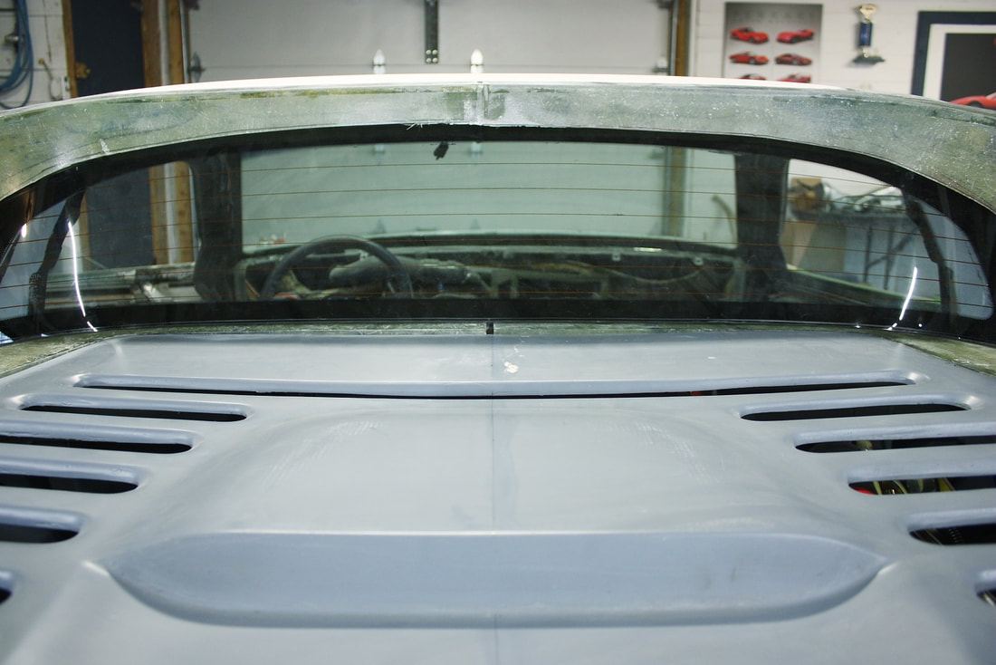
From the underside the longitudinal stiffeners are much more obvious, and appear to serve two other purposes: hold the underlying mesh screen in place, and provide a mounting surface for the hinges:
From the underside the longitudinal stiffeners are much more obvious, and appear to serve two other purposes: hold the underlying mesh screen in place, and provide a mounting surface for the hinges:
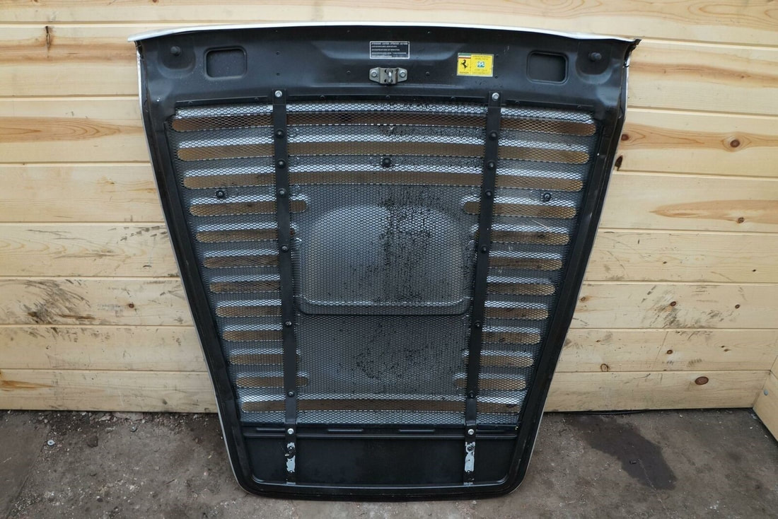
The close up also shows what appears to be a perimeter frame made from square tubing. The give-away is the indented walls in the tight radius bends at the front corners shown here:
The close up also shows what appears to be a perimeter frame made from square tubing. The give-away is the indented walls in the tight radius bends at the front corners shown here:

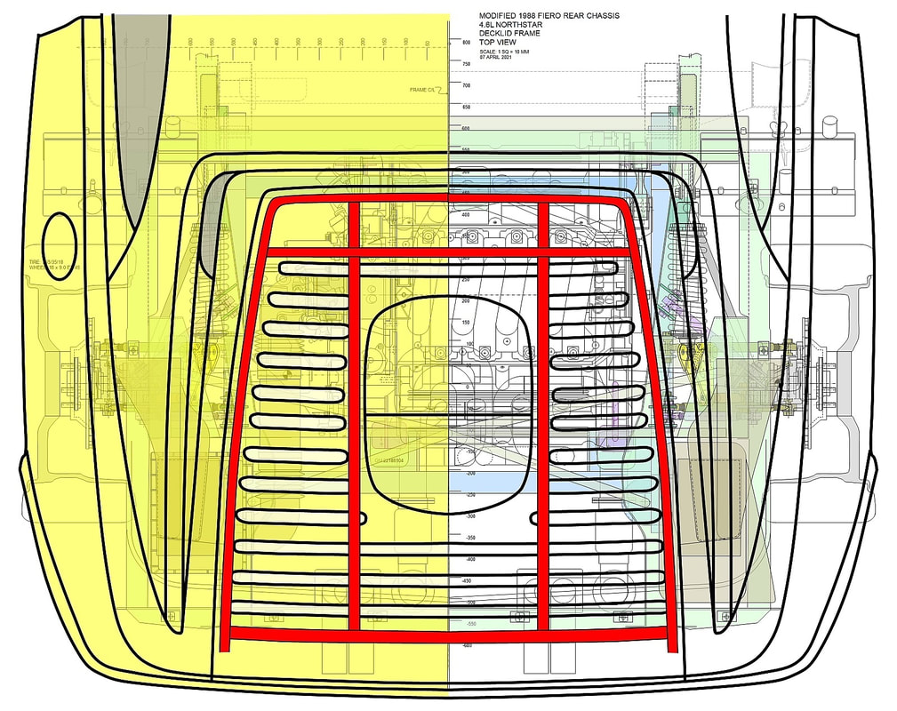
Knowing what the real Ferrari’s structure looked like allowed me to draft up a plan for a frame to straighten, stiffen, and provide mounting points for my own car’s decklid:
Knowing what the real Ferrari’s structure looked like allowed me to draft up a plan for a frame to straighten, stiffen, and provide mounting points for my own car’s decklid:
But I knew I couldn’t simply build a decklid frame without considering what hinges I would use. Space is very limited in the hinge area of my car. So again I looked for inspiration to the authentic F355. This next photo is of the hinges from an F348, but the F355’s are identical:
But I knew I couldn’t simply build a decklid frame without considering what hinges I would use. Space is very limited in the hinge area of my car. So again I looked for inspiration to the authentic F355. This next photo is of the hinges from an F348, but the F355’s are identical:
They conveniently mount to the longitudinal stiffeners attached to the decklid, have gas springs, and have a pivot point hidden from view that appears to be quite high near the base of the rear window.
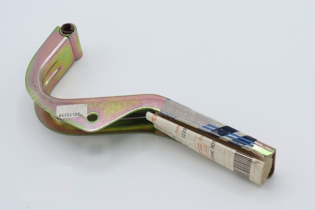
eBay came in handy once more where I was able to find a photo of an authentic hinge with a bit of searching:
They conveniently mount to the longitudinal stiffeners attached to the decklid, have gas springs, and have a pivot point hidden from view that appears to be quite high near the base of the rear window.
eBay came in handy once more where I was able to find a photo of an authentic hinge with a bit of searching:
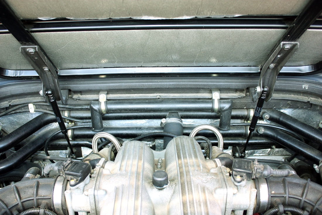
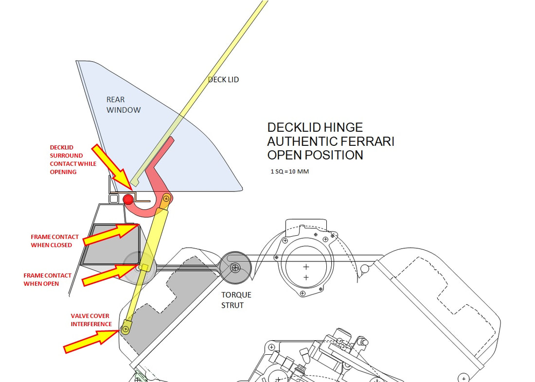
But that’s where my luck ended with the authentic design because after replicating several versions in cardboard, there was no way to mount the pivot point of a simple hinge high enough in my chassis to make it to work. In every case where I could make a reasonable gap between the front edge of the decklid and the surrounding bodywork, the front edge of the decklid would contact the bodywork when opened, or the hinge would hit the cross car frame when closed. Furthermore, the proximity of the front valve cover left no room for gas springs to be mounted vertically:
But that’s where my luck ended with the authentic design because after replicating several versions in cardboard, there was no way to mount the pivot point of a simple hinge high enough in my chassis to make it to work. In every case where I could make a reasonable gap between the front edge of the decklid and the surrounding bodywork, the front edge of the decklid would contact the bodywork when opened, or the hinge would hit the cross car frame when closed. Furthermore, the proximity of the front valve cover left no room for gas springs to be mounted vertically:
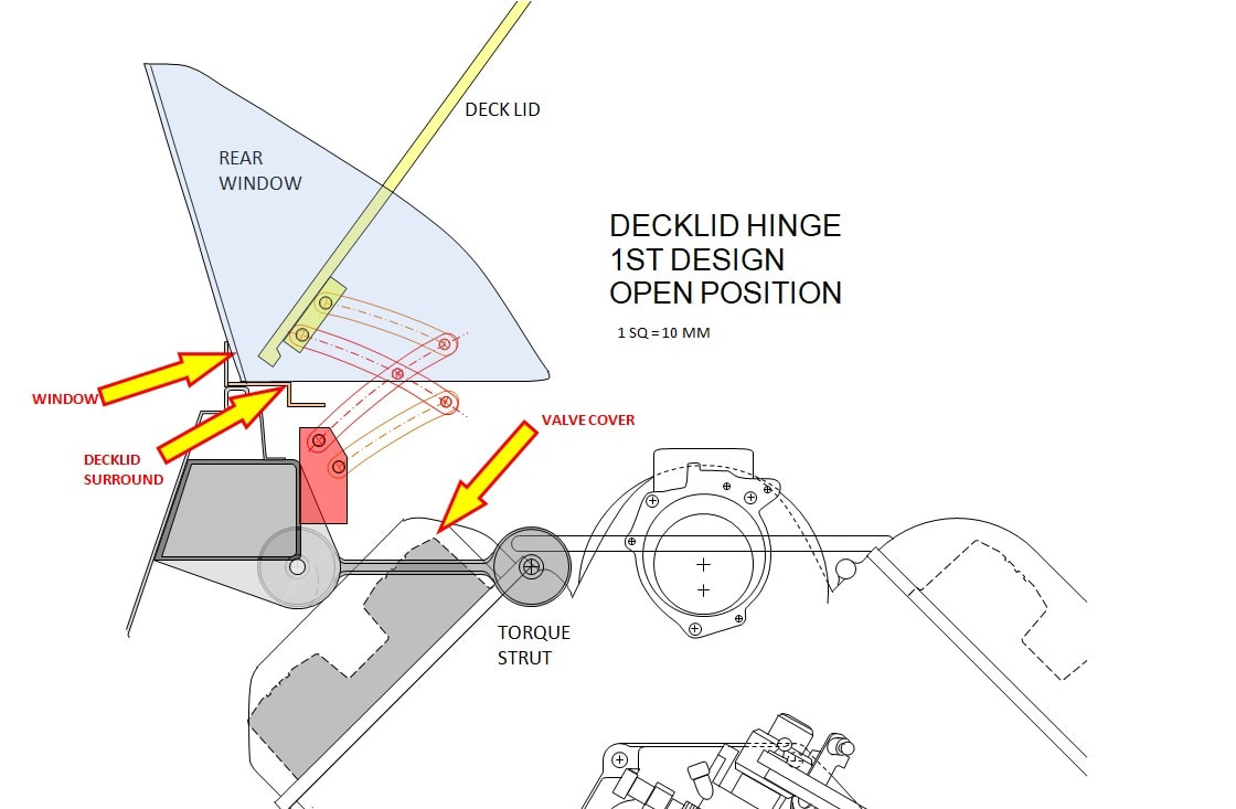
I needed a compact hinge design that would pull backward slightly while raising upward. That automatically meant I’d need a scissor hinge of some type. After hours of research I wasn’t able to find a commercially available scissor hinge that met all of my design criteria, so I decided to try and design my own. This next drawing was my first attempt but the design ultimately failed because it too could not be made to work without either contacting the valve cover when closed, or the deck lid surround when opening. Neither could I find a reasonable way to attach a gas spring, nor a clean way to keep the hinge from over-extending and allowing the decklid to contact the rear window:
I needed a compact hinge design that would pull backward slightly while raising upward. That automatically meant I’d need a scissor hinge of some type. After hours of research I wasn’t able to find a commercially available scissor hinge that met all of my design criteria, so I decided to try and design my own. This next drawing was my first attempt but the design ultimately failed because it too could not be made to work without either contacting the valve cover when closed, or the deck lid surround when opening. Neither could I find a reasonable way to attach a gas spring, nor a clean way to keep the hinge from over-extending and allowing the decklid to contact the rear window:
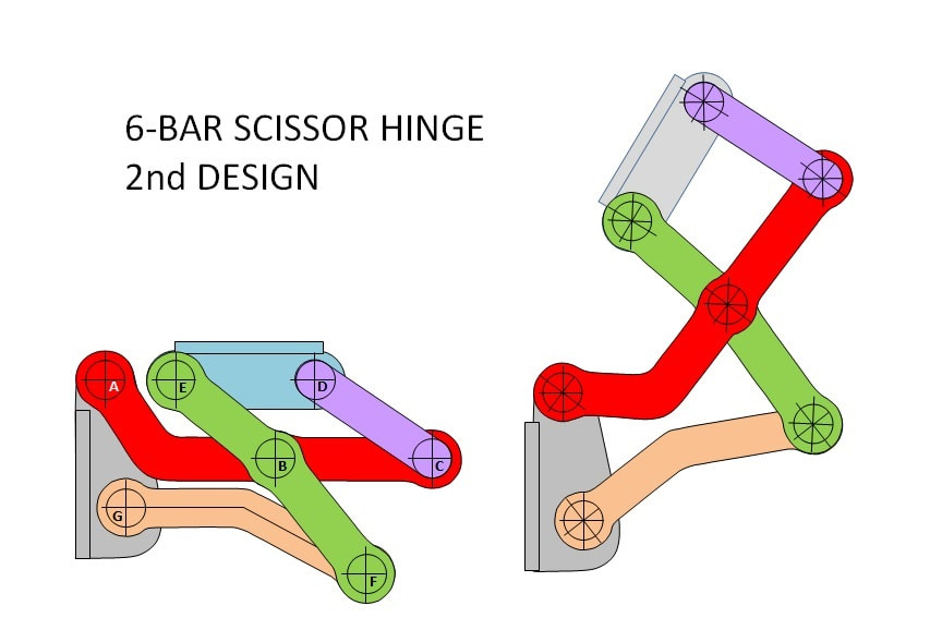
Finally, after getting inspiration from some cabinetry hinge catalogues, I worked out a second design on my computer that was robust, compact, and had the required range and arc of motion:
Finally, after getting inspiration from some cabinetry hinge catalogues, I worked out a second design on my computer that was robust, compact, and had the required range and arc of motion:
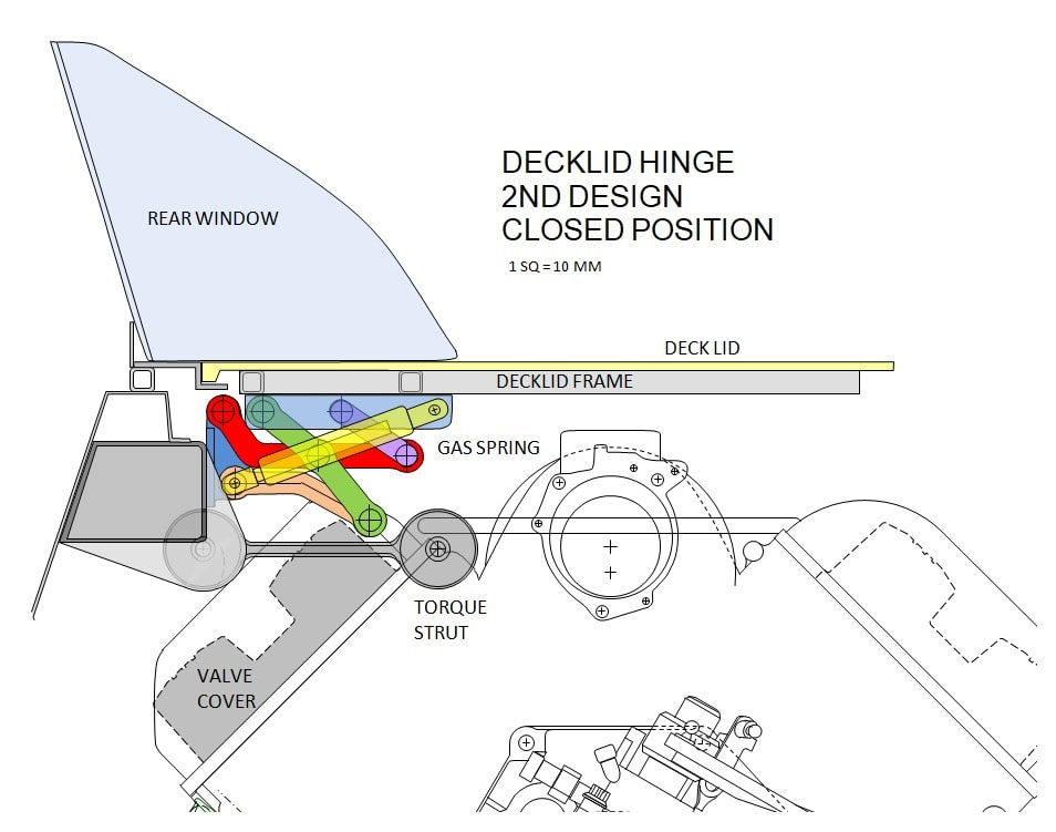
With my handy-dandy general layout drawings I had created earlier, I was able to work out the precise dimensions to clear the valve cover and torque strut when closed, and incorporate a gas spring (yellow component) as well:
With my handy-dandy general layout drawings I had created earlier, I was able to work out the precise dimensions to clear the valve cover and torque strut when closed, and incorporate a gas spring (yellow component) as well:
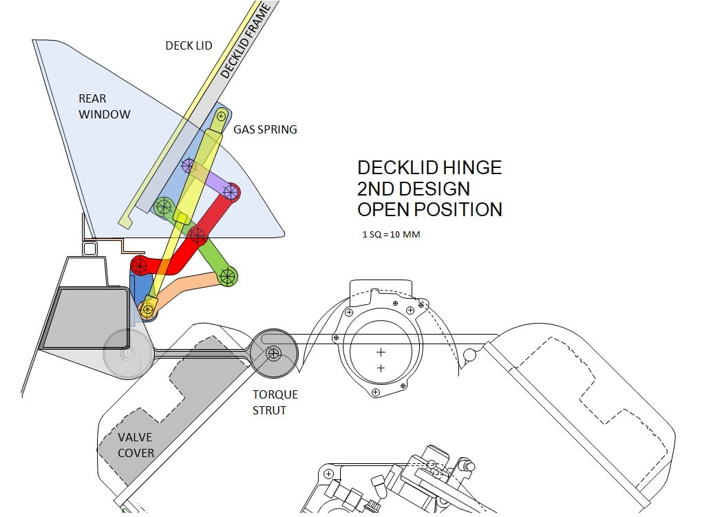
When opened, the hinge pulled slightly backwards first, clearing the decklid from the surround, used near full travel of the same model gas spring as the front compartment, and automatically limited the travel of the decklid to prevent contact with the rear window:
When opened, the hinge pulled slightly backwards first, clearing the decklid from the surround, used near full travel of the same model gas spring as the front compartment, and automatically limited the travel of the decklid to prevent contact with the rear window:
It worked well enough on “paper”, but since this was the most critical part of the deck lid mounting, I hired a friend to convert my 2D drawings into 3D and run a simple animation to determine if any of the pivot points would bind within the range of motion I needed.
It worked well enough on “paper”, but since this was the most critical part of the deck lid mounting, I hired a friend to convert my 2D drawings into 3D and run a simple animation to determine if any of the pivot points would bind within the range of motion I needed.
The animation would have broken down if any of the 7 pivot points bound up during cycling, but it worked flawlessly.
The next step was to confirm if there would be any interference with the myriad components under the hood, so I decided to have a full-sized prototype hinge 3D printed for form, fit, and function testing:
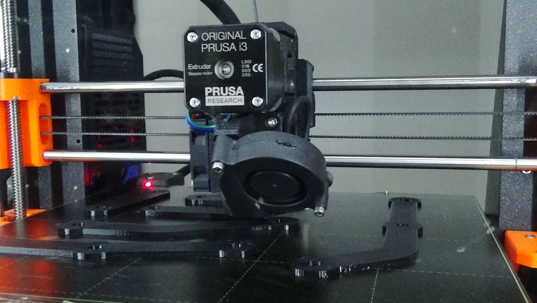
The 3D printing was done by a friend for the cost of the materials only, so about $3. I had nothing to lose and everything to gain since my end goal was to have the pieces CNC milled from aluminum plate. The cost of discovering a problem at that stage would have been significantly greater.
The priority of printing my hinges wasn’t very high, so you’ll have to wait (as I did) to see the results.

 RSS Feed
