This is a place-holder to reserve the space for future chassis posts on the fuel system installation.
|
|
|
This is a place-holder to reserve the space for future chassis posts on the fuel system installation.
5 Comments
Having ironed out the bulk of the front compartment structure, I tore it all apart to clean the fingerprints off the bare sheet metal, hit it with some Duplicolor self-etching primer, then applied a coat of 2K epoxy primer to everything: 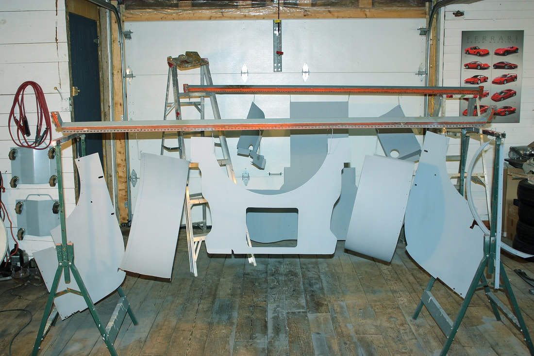 Once the epoxy had cured, I pinned it all back together again using Cleco fasteners to plan out which pieces should be permanently fastened to the chassis, and which ones I would make removable for access later on. When I stepped back I couldn’t help to think it looked like a cow-catcher on a train!: 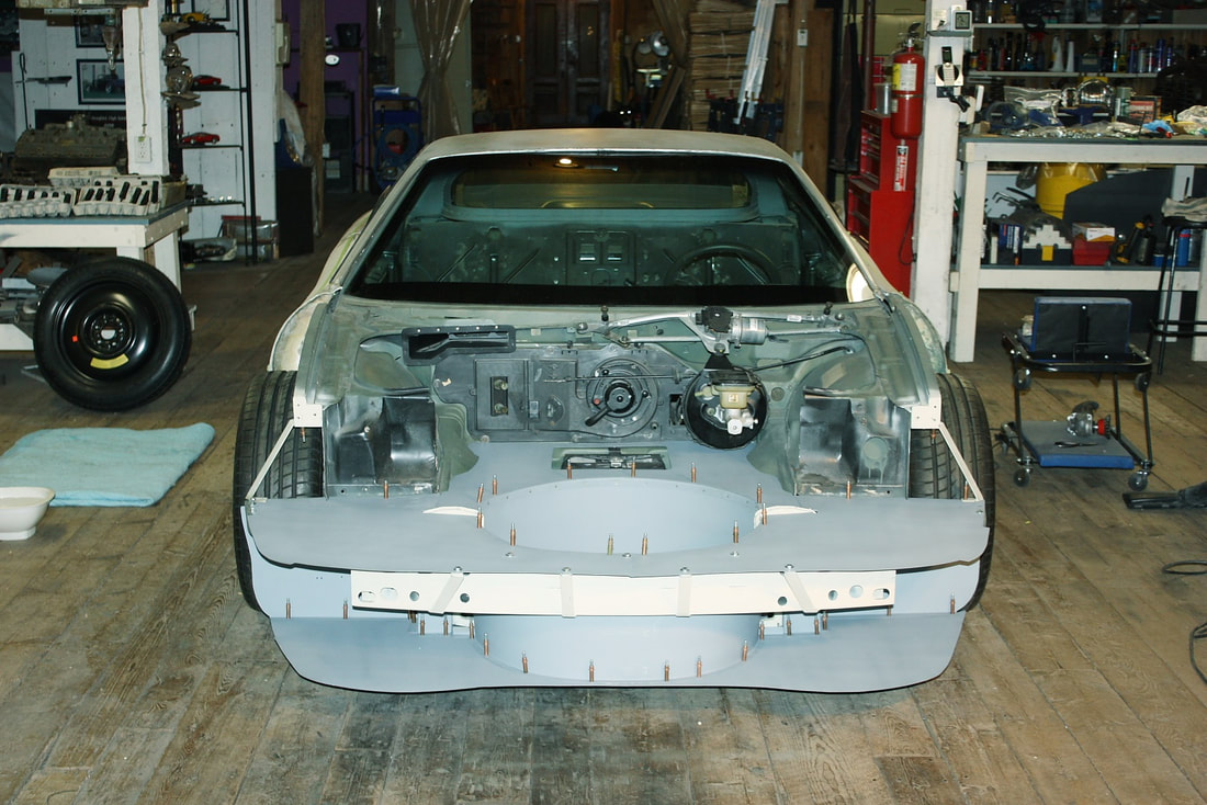 And from the top view it sorta looked like a hammerhead shark! 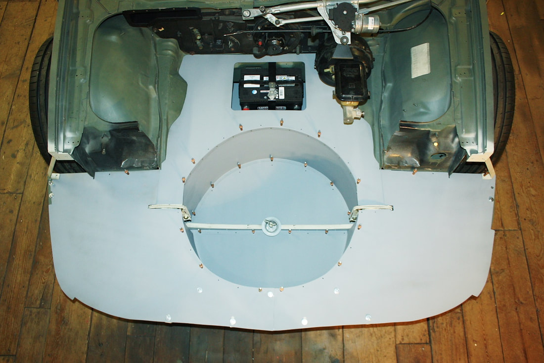 When I slipped the lower fascia back on, I realized I’d have to address a problem that's been brewing ever since I started compartmentalizing the front end: Airflow into the front grill would have nowhere to go: 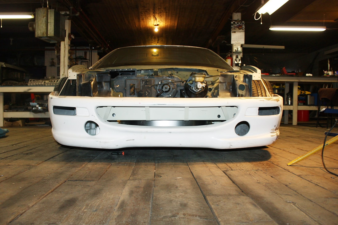 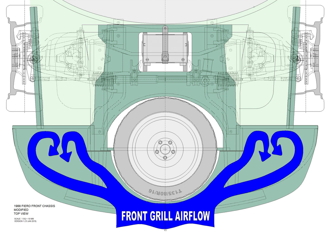 I thought about making rear facing louvers in the undertray, but then that would've just crammed high pressure air under the car and generated front end lift. Then I thought about ducting the air to the HVAC inlet, which I'll probably do, but not now. Finally, although my driving style won’t require it, I decided to duct the air to the front brakes: 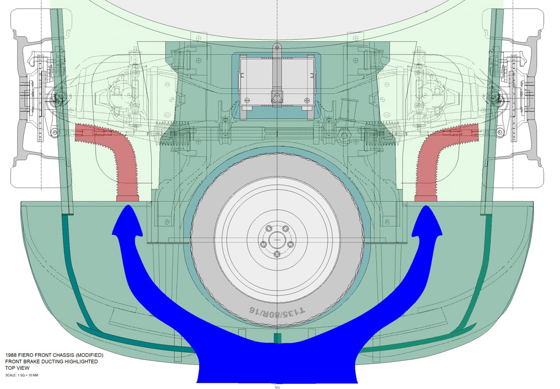 I started by cutting a 3” diameter hole into each of the bulkheads that separate the front compartment from the wheel well: 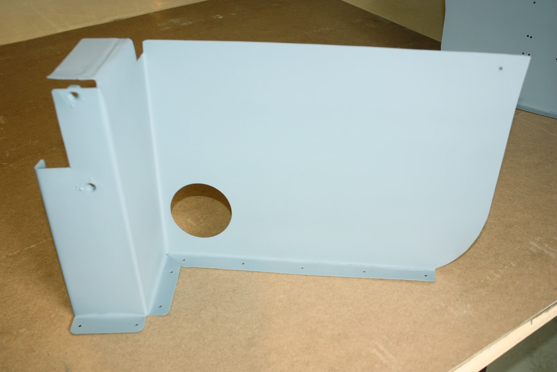 Then I bought a pair of 3” diameter vents from the local hardware store and proceeded to open them up, effectively turning them into mounting flanges for the ducting. I cut out the louvers but left the screening in place for now: 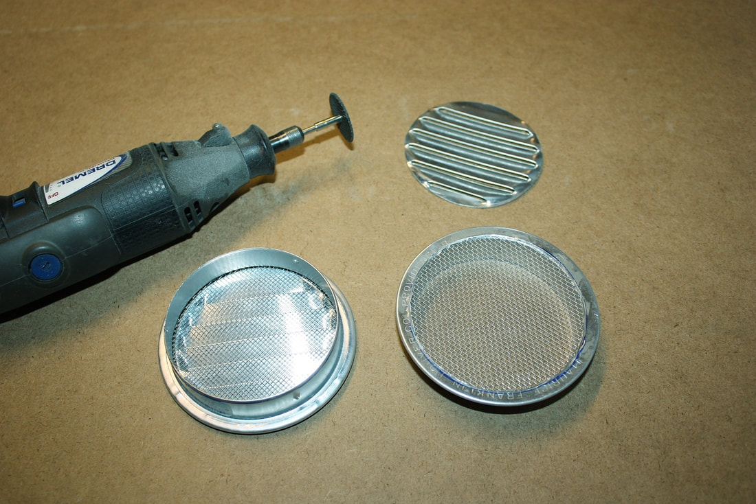 They slipped nicely into place, and were pretty solid after riveting them to the bulkheads: 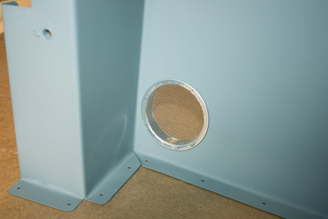 Then I reinstalled the bulkheads: 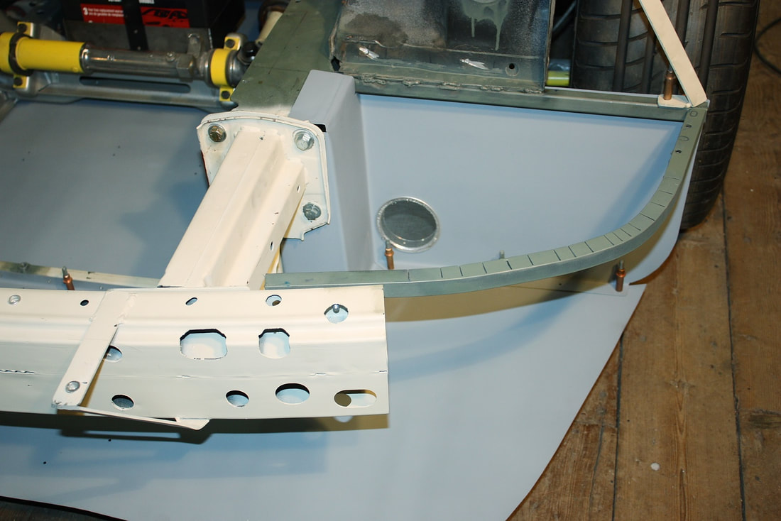 From this view you can see the brake duct flange (yellow arrow) sticking out into the wheel well, with the lower control arm and wheel in the background: 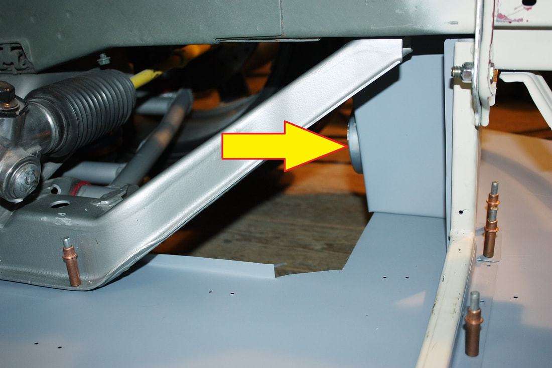 I bought some 3” diameter aluminium flex hose for use with a clothes drier for the actual ducting. At $12 it won’t be much of a loss if it turns out to be too flimsy for the job. In the meantime, I’ll keep my eyes open for something a little more robust: 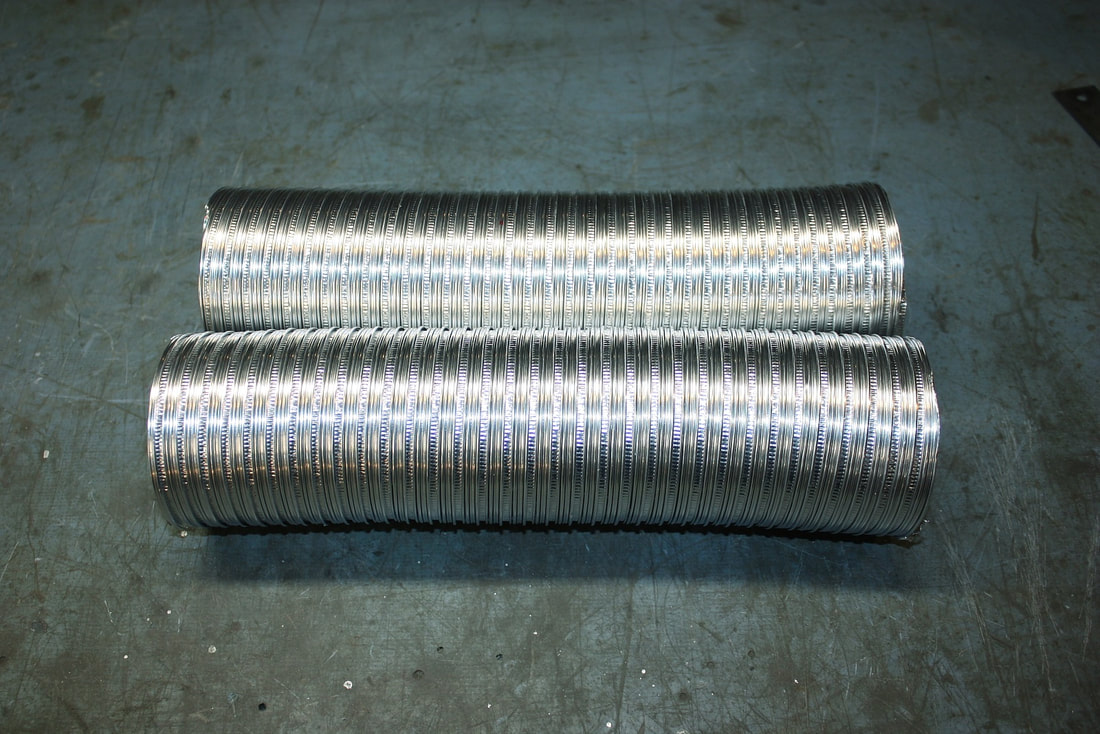 After forming 90 degree elbows in the ducting, I slipped them into place with ease: 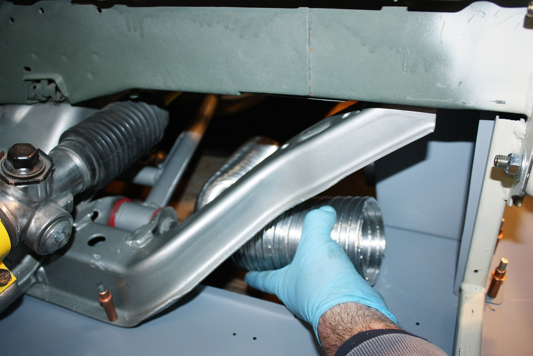 Then I clamped them to the freshly installed mounting flanges with a hose clamp. They’ll have to be clamped to the lower control arm as well in order to move up and down with the wheel, and they’ll have to be positioned to clear the steering arc of the tire as well, but I’ll work those details out later: 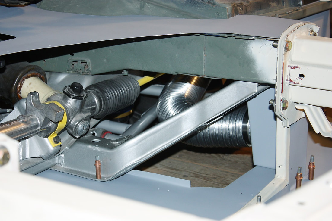 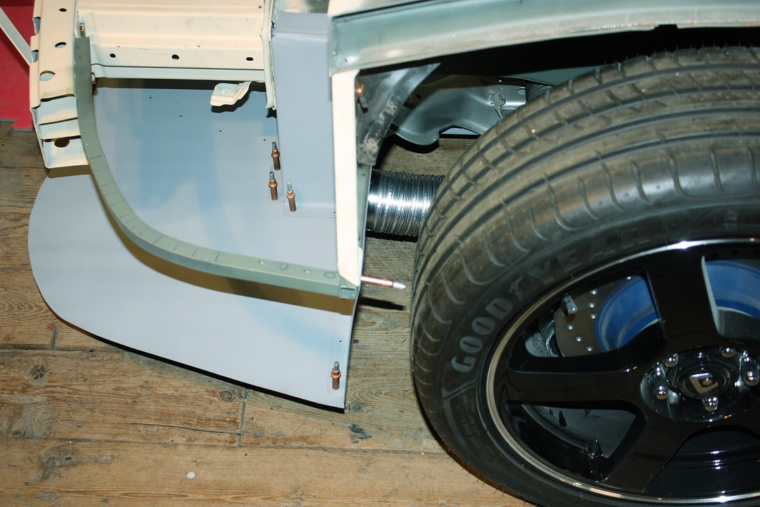 Whether two 3” ducts are going to be enough to vent the ram air coming through the front grill is yet to be seen, but if not, I can always put extra louvers in the bulkheads to vent excess pressure into the wheel wells. Since I was working in the general area, I decided I should at least plan the layout for a few other miscellaneous front end components. I'll use the passenger side front bulkhead to mount the horns and possibly a filter box for the HVAC system. Note how the HVAC inlet at the base windshield on the passenger side lines up well with this area. The driver’s side will get the windshield washer reservoir: 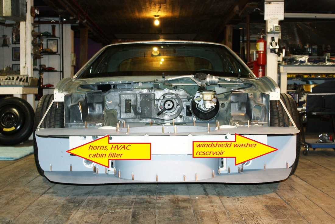 Knowing what physical space was available for the windshield washer reservoir, I set off for the salvage yard again, this time hunting for a part that’s often hidden behind body panels. Luckily I didn't have to look too long before stumbling across a 2010 Ford Fusion with the RH front fender and facsia removed. It looked to be the perfect shape and size! 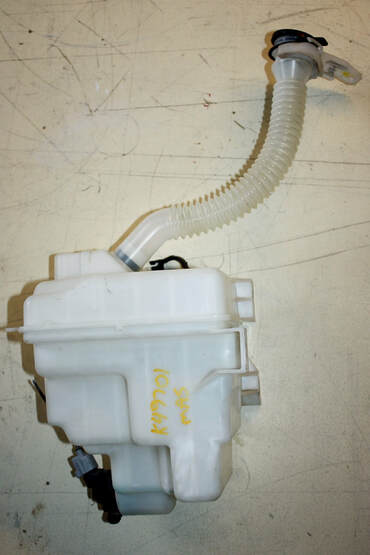 And because of my crazy desire to document everything, I drew it out in two dimensions… 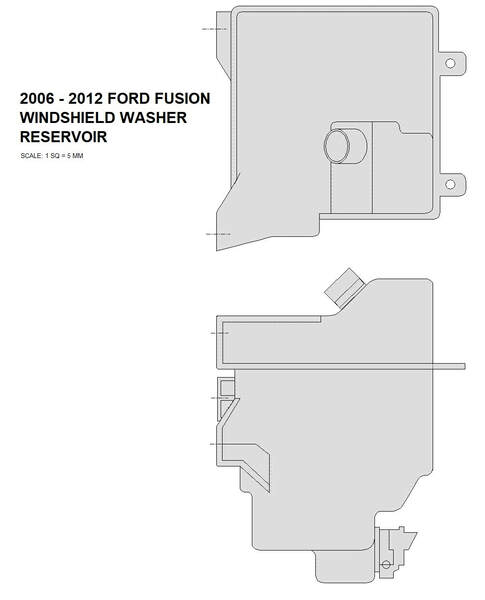 … and added it to my chassis drawings: 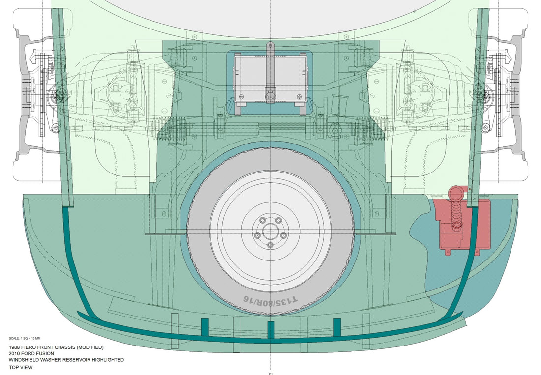 The front compartment bulkhead that I wanted to mount the reservoir to, wasn’t made perfectly vertical… I made it with a 10 degree slant, which meant that I’d have to make oppositely angled mounts for the reservoir to sit level. Since I needed three mounts for the reservoir, and since they were all at different heights, I was able to form a single 10 degree bracket that I could simply cut in three pieces: 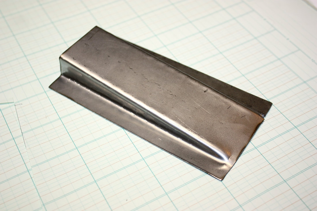 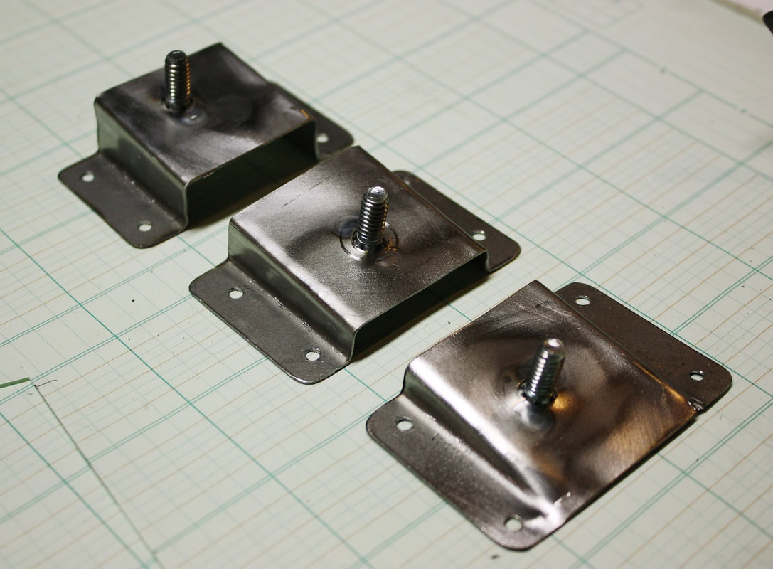 After marking the appropriate spots on the bulkead, I drilled mounting holes and mocked up the mounts: 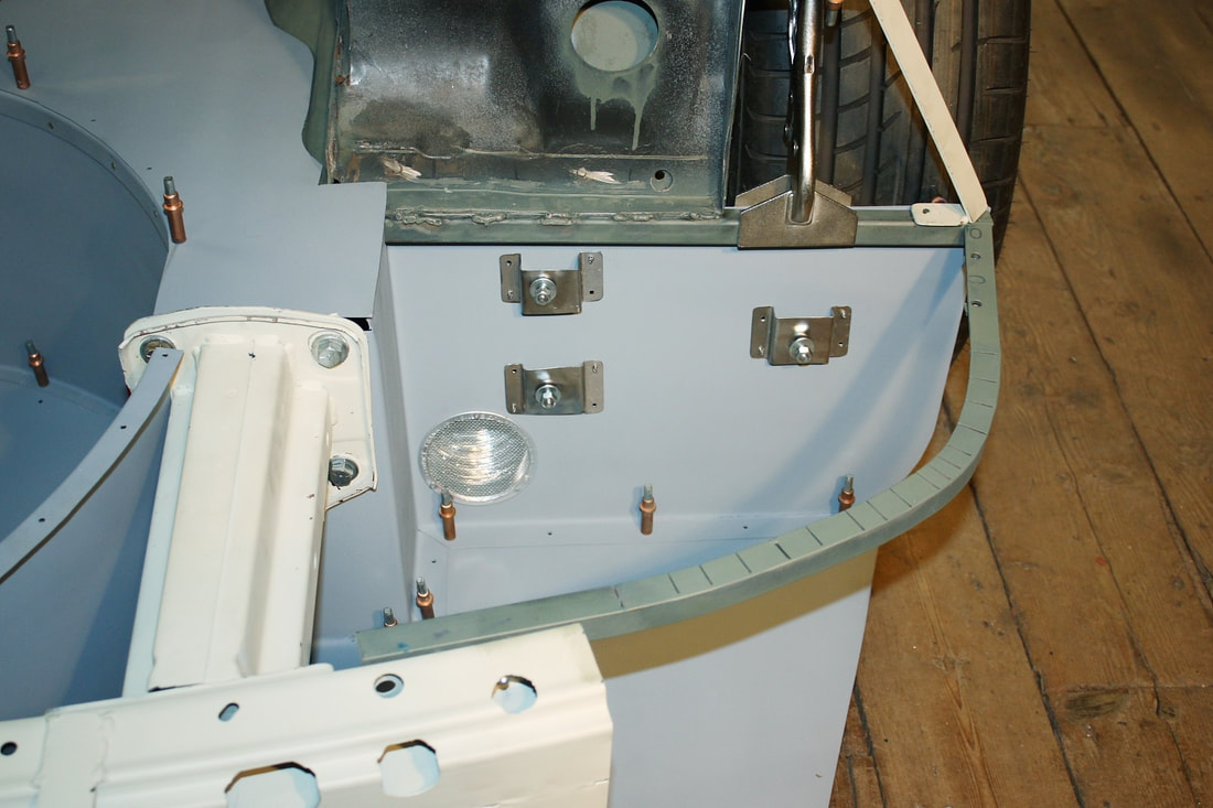 Then I bolted the reservoir to the bulkhead… easy peasy. Even the filler neck turned out to be at the right height to bolt to the upper frame rail. I’ll shorten the mounting tab on the neck to straighten it out. 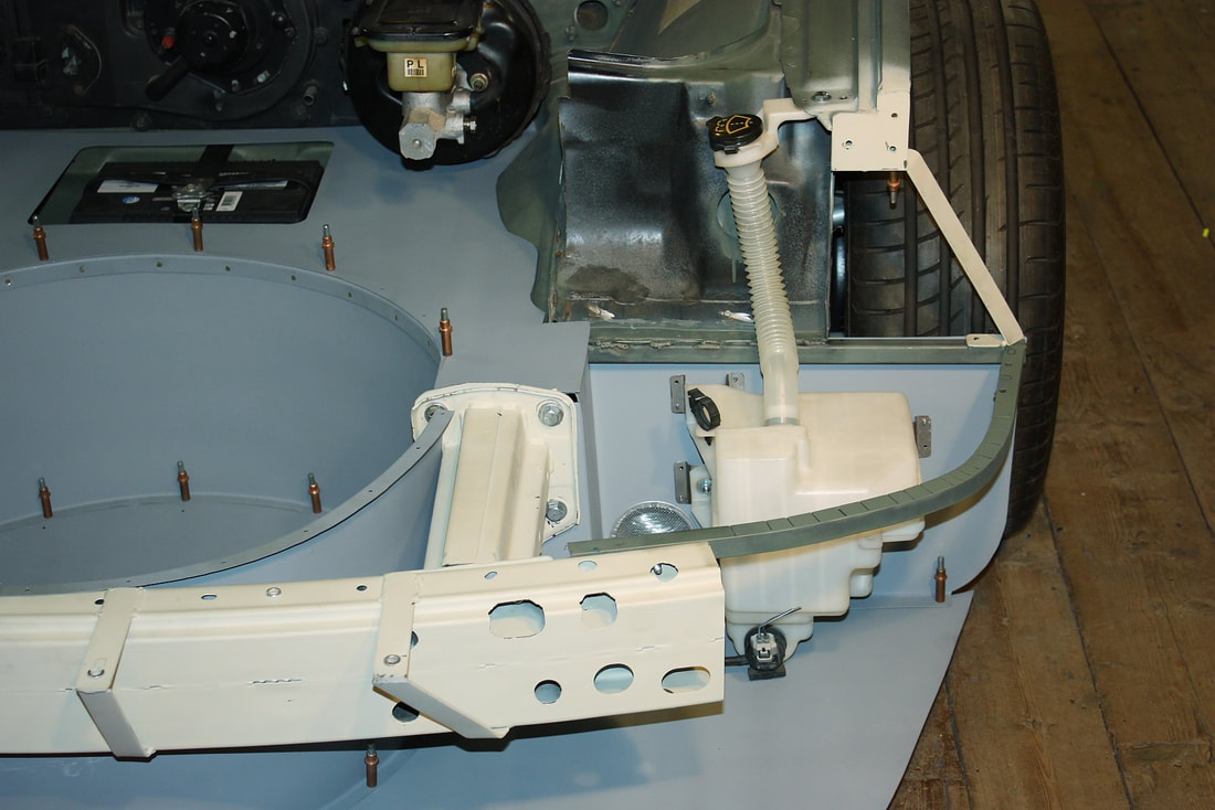 Finally, this next photo shows why I needed the funky mounting brackets I made to get the tank sitting level, and to direct the last little bit of fluid to the side with the pump: 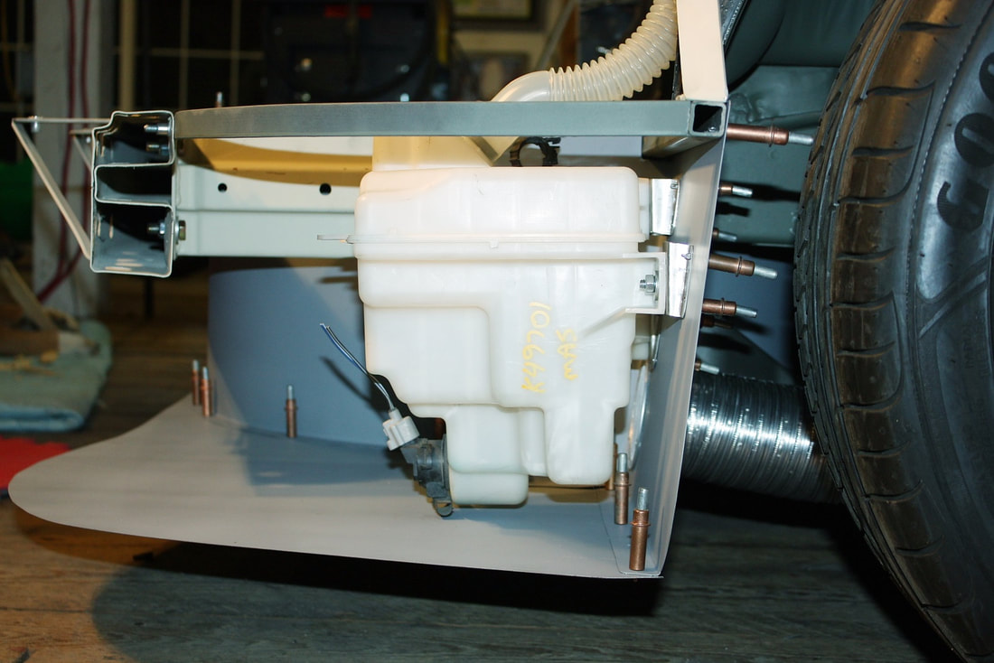
I'll use a similar approach to install the horns and HVAC cabin filter on the passenger side, so I'll spare you the details. Besides, I've got to keep the last two posts I've reserved in this section to cover the entire fuel system at some later point. For now though, it’s time to head over to the Body section! With the spare tire and battery locations sorted out, I was finally ready to seal the lower portion of the front compartment from the upper half, which would become the luggage compartment. Since the area where the battery is located is open to the elements via the wheel houses, a large tailor cut sheet (yellow arrows) would serve to divide the wet and dry compartments. 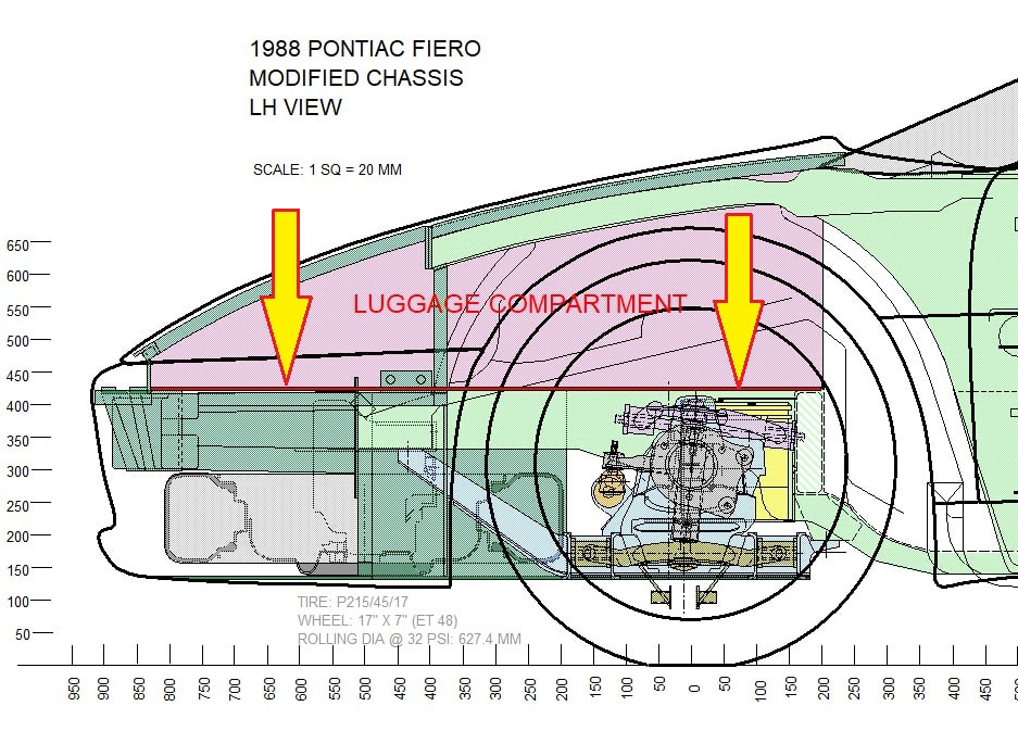 It would have to be done in several pieces if I wanted it to fit tightly, so I started by planning a piece to seal off the battery compartment, like so: 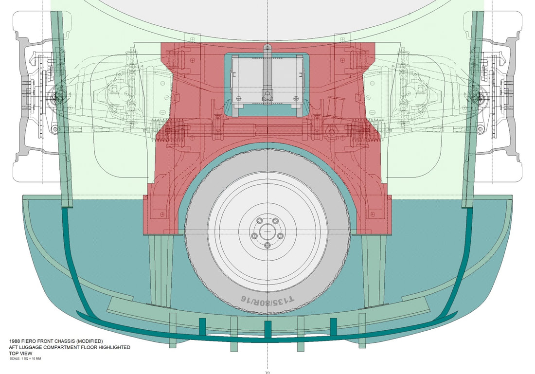 I made a paper template (as always), then trimmed and modified it numerous times until it fit just right side-to-side between the lower frame rails, and front-to-back between the curved flange of the spare tire well and the main cabin cross member: 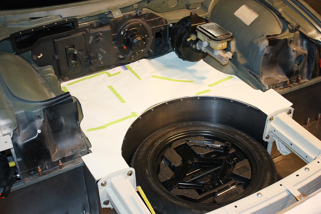 Then, I traced the template onto some 22 gauge steel, and cut it out with a thin cut-off wheel on the angle grinder. After de-burring the edges, it slipped right into place like a factory part: 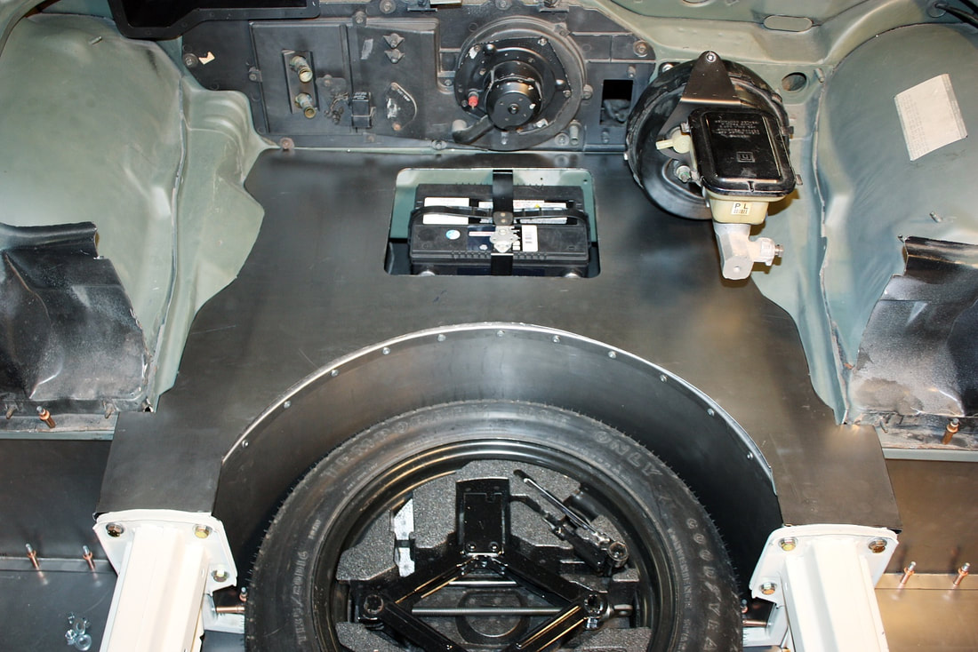 I wanted to be sure I’d have unrestricted access to the battery from above, in case I ever needed to change it, so I carefully measured the location of the battery and cut a hole in the floor panel. I’ll eventually create an access door to cover the hole: 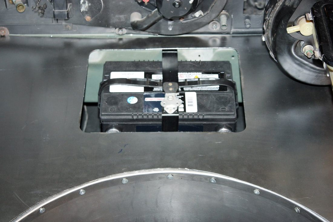 Next, I needed to seal off the upper luggage compartment from the dirty air coming through the front grill. This forward section of the luggage compartment floor will also serve as a mounting surface for the headlights and hood hinges later on: 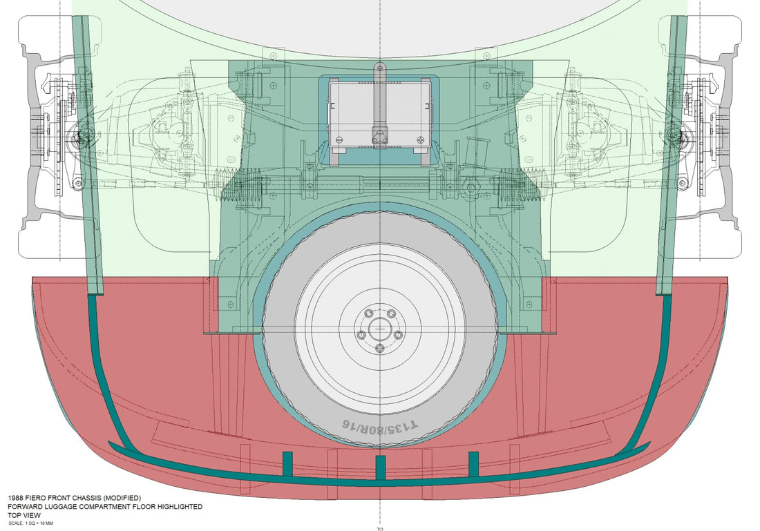 Once again I resorted to my bristle board stocks to make a pattern for the floor panel. Rather than try to make one “go” of it, I made the half-template in several pieces to fit tight areas perfectly, then taped them together: 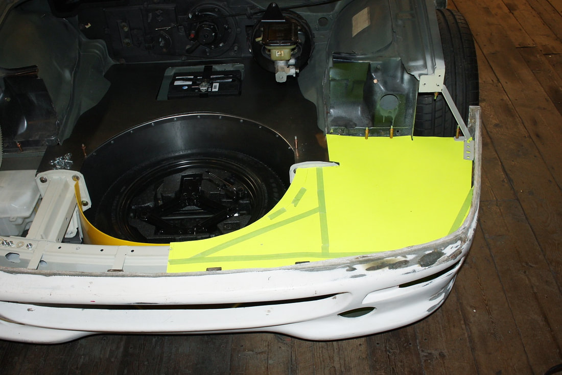 Then I traced out the template on some more 22 gauge steel and cut it out: 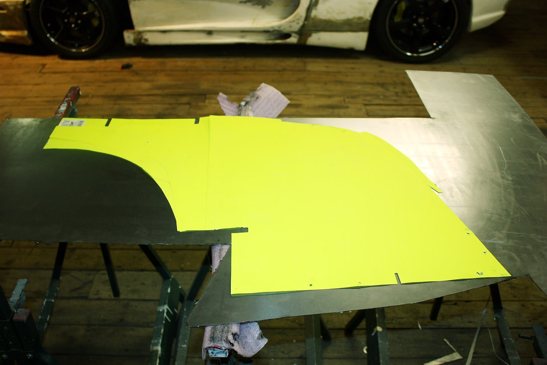 It took a bit of flexing and some final tweaking but the driver’s side floor panel fit like a glove. Then I simply turned the template upside down, fit it to the passenger side, made some minor changes to it since both sides aren’t perfectly symmetrical, and I was ready for the second half: 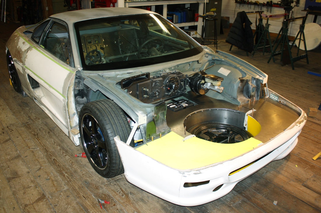 After a bit more fitting and jostling, the passenger side luggage compartment floor fit into place and was also ready for duty: 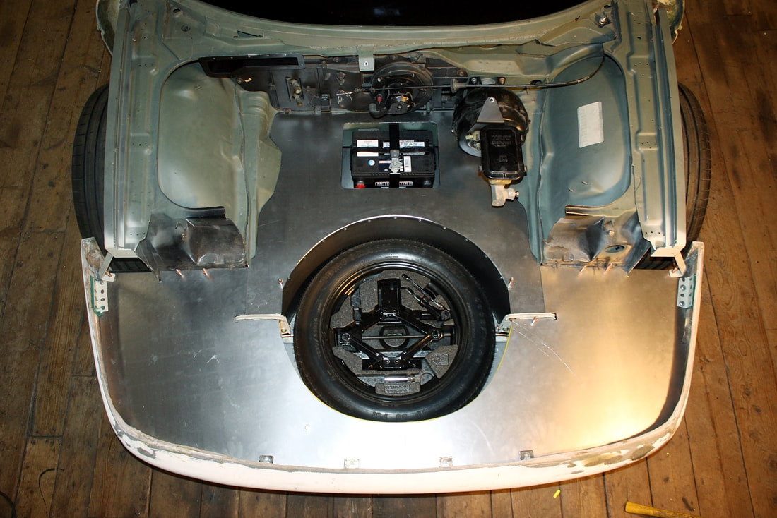 As it stood, these two forward pieces were supported with flanges and structures lying beneath them everywhere except along the curved edge of the spare tire well. Since I also needed a way to seal off the front of the well from the dirty air coming in through the front grill, I had one more piece to make: 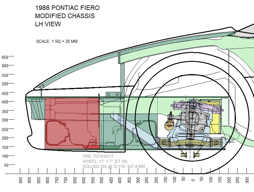 Using cardboard is tricky for a curved template since it doesn’t hold its form very well so I opted to make it out of Coroplast. Provided it’s flexed the right way in relation to its internal ribbing, the Coroplast springs nicely into a continuous curve: 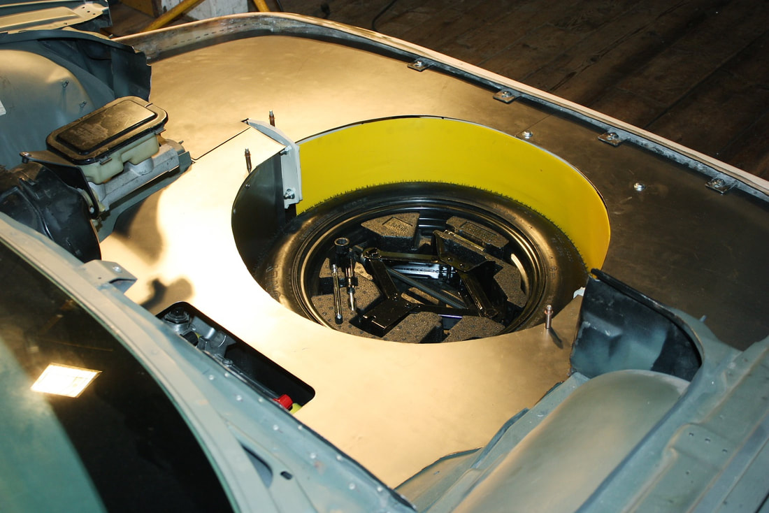 Here’s a better view through the front grill of why it’s needed: 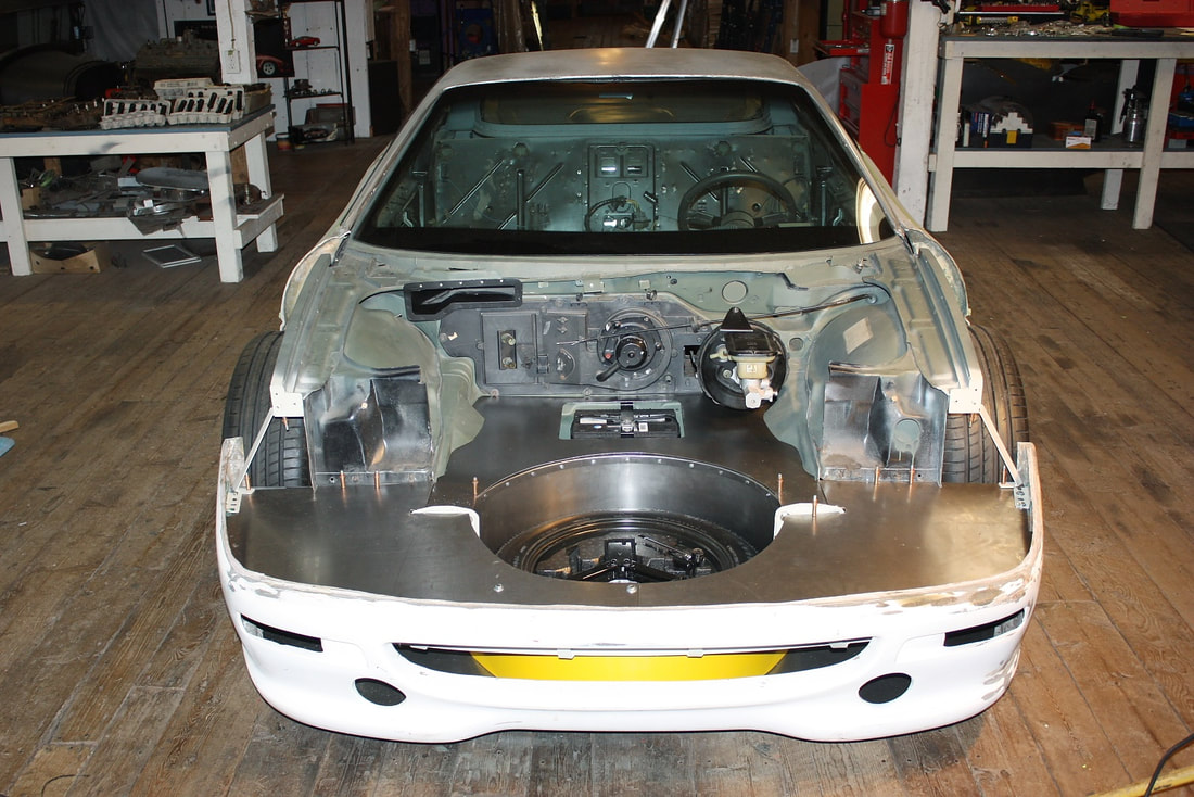 I cut some 22 gauge steel according to the template, bent some 90 degree flanges along the two longest edges, then curved the flanges on the stretcher, and ended up with the forward spare tire well wall: 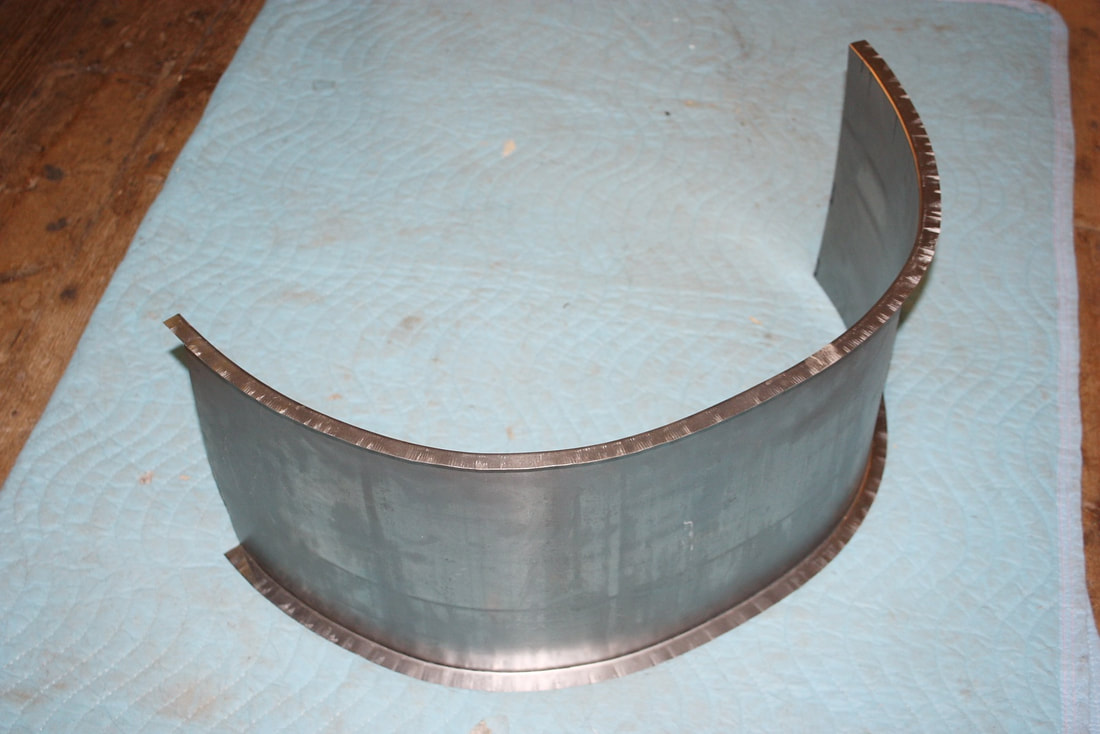 Once mocked up into place, it sealed off the tire well, and gave me the flanges I needed to secure the undertray and the luggage compartment floor to it: 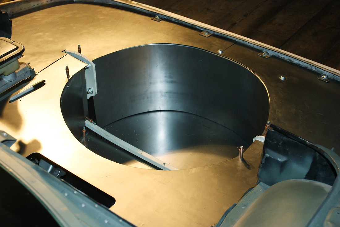 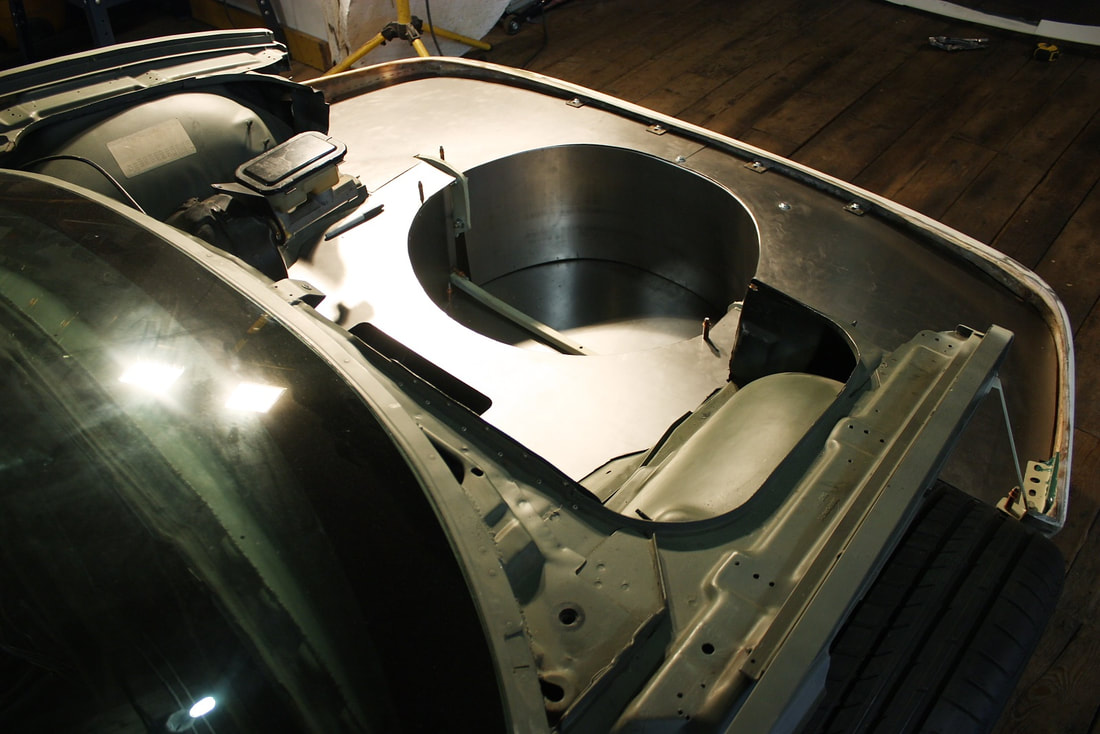 With everything mocked up at this point, I was ready to disassemble the whole front end sheet metalwork, finalize all of the attachment points, prime and paint it, and plan my next move: 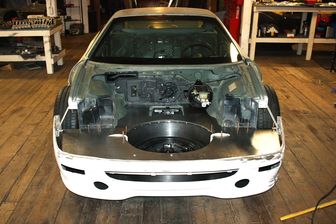 My next challenge was to find a space-saver rim that would have the correct bolt pattern to fit my hubs, and have the right offset and overall diameter and clear my brake hardware. I wanted a space-saver primarily to save money: a full size Motegi alloy wheel and performance tire here in Canada would’ve cost me upwards of $450, and might never be used, whereas a junk yard space-saver might cost $20, and save a bit of weight and space. My job was made considerably more difficult when I discovered the local salvage yard removes all the spare wheels from their vehicles, using them to prop up the carcasses of stripped out chassis. After 2 hours of searching I found a spare wheel in a 1st generation Subaru Outback that they had forgotten in the trunk. The rim looked nearly perfect with a 16” dia, 5 x 100 mm bolt pattern, and a 48 mm offset. The hub bore was 1 mm smaller than needed, and the tire size was too large, but both of those issues could be managed: 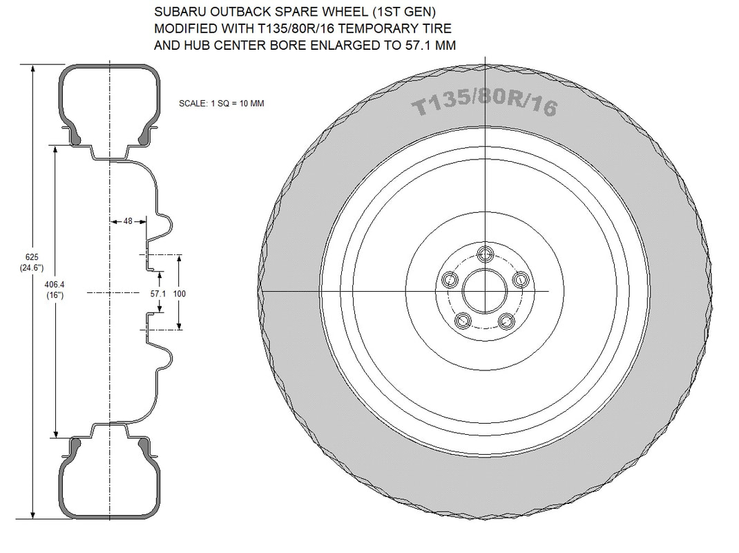 The stock T145/80/16 tire was about 5/8” too big in diameter, so I scrounged around for another hour before finding a T135/80/16 tire from 2014 Honda Insight. Of course the Insight’s rim was all wrong, but all I needed was the tire. So for $20 I left the salvage yard with two wheel assemblies and a plan to make my Franken-wheel. Another $10 was spent at the local garage to swap the tires and I came away a happy customer: 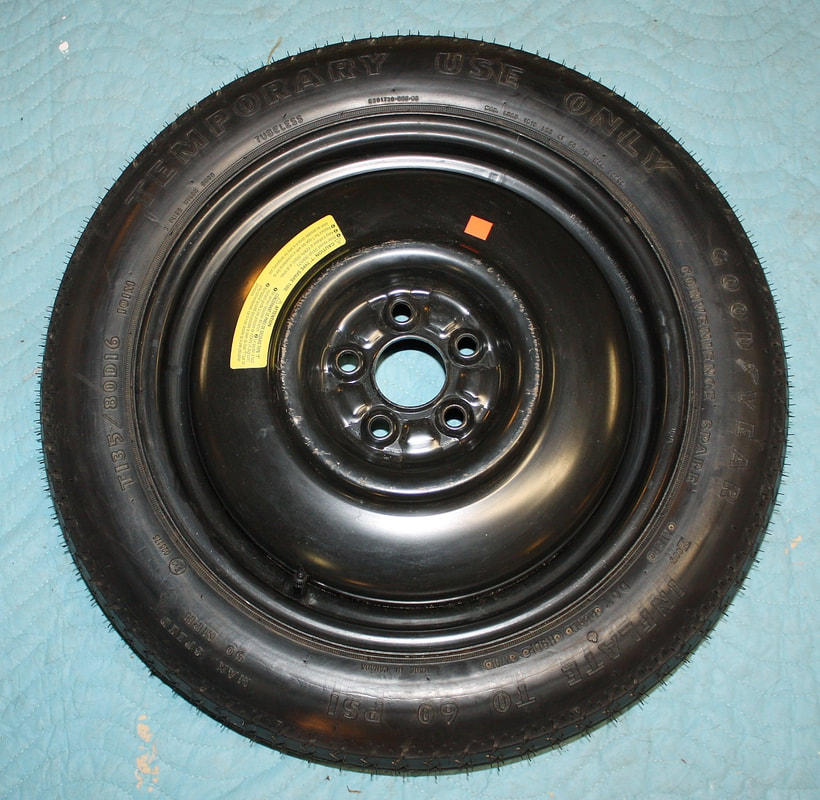 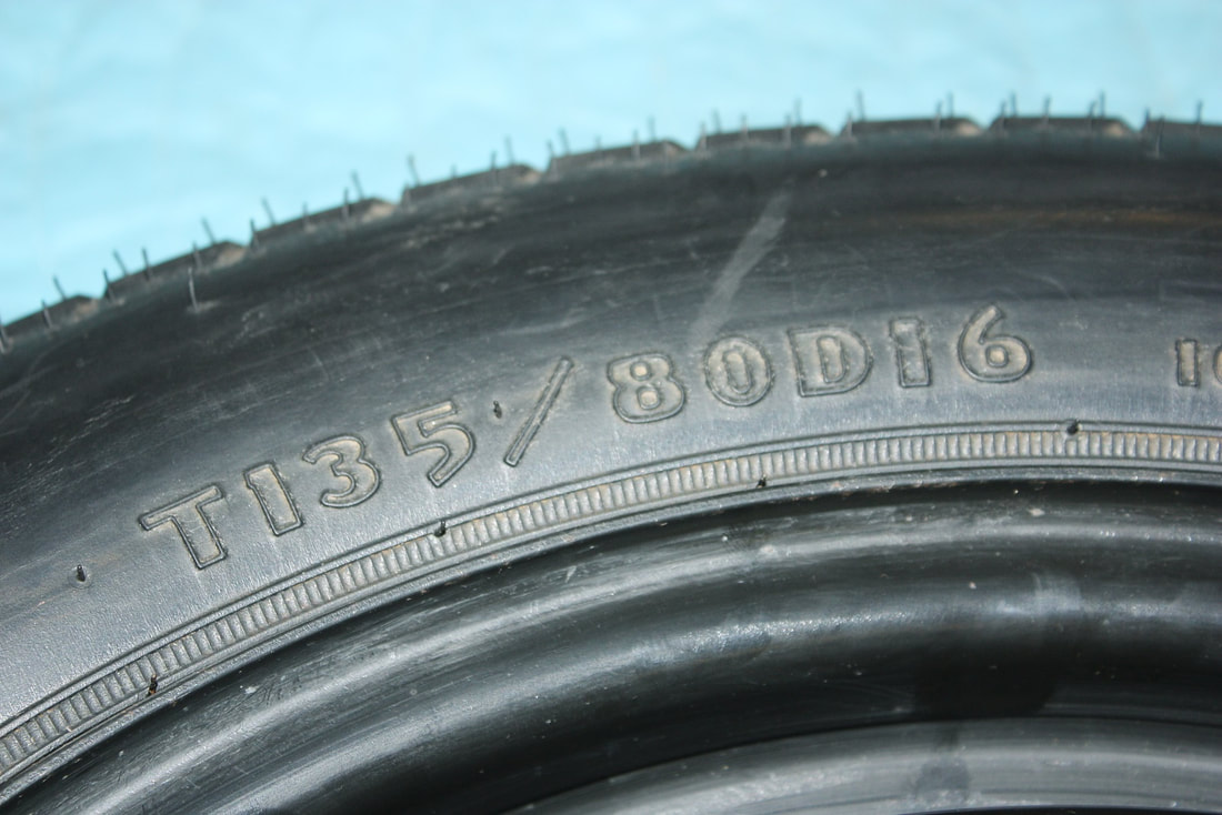 My field calculations told me that the Subaru rim would clear my C4 Corvette brakes, but I test fitted it to make sure. Then I drew up this schematic showing by how much I was in the clear: 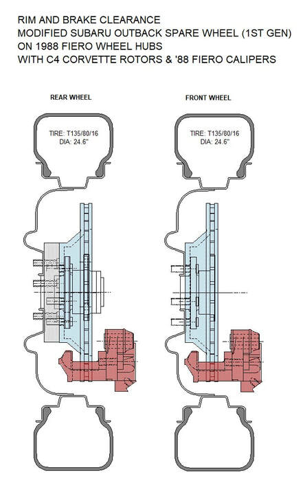 Then, I updated my digital chassis drawing to include the new hybrid temporary spare wheel: 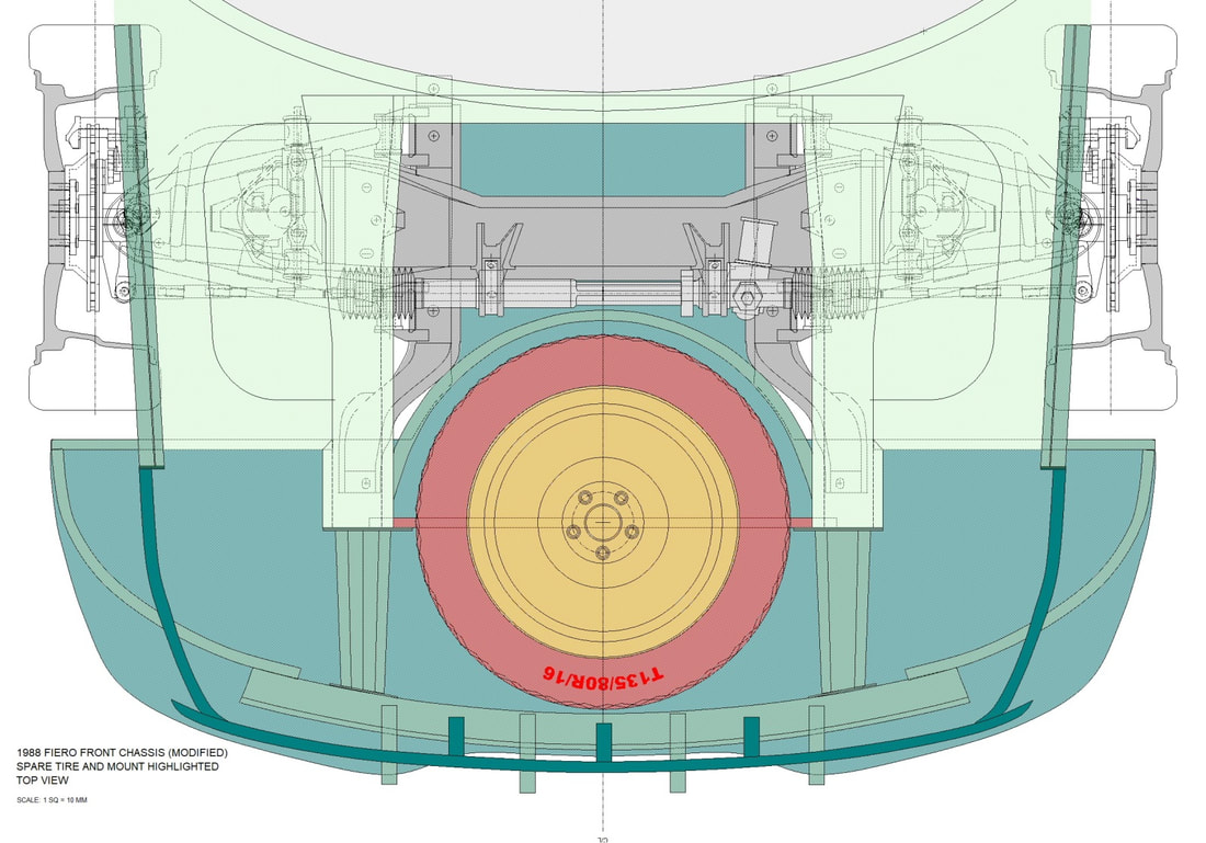 I also test-fitted the wheel to my new spare tire compartment, then marked and tapped the square tube support under it, for the hold-down bolt. I used the hold-down hardware I scarfed from the Subaru: 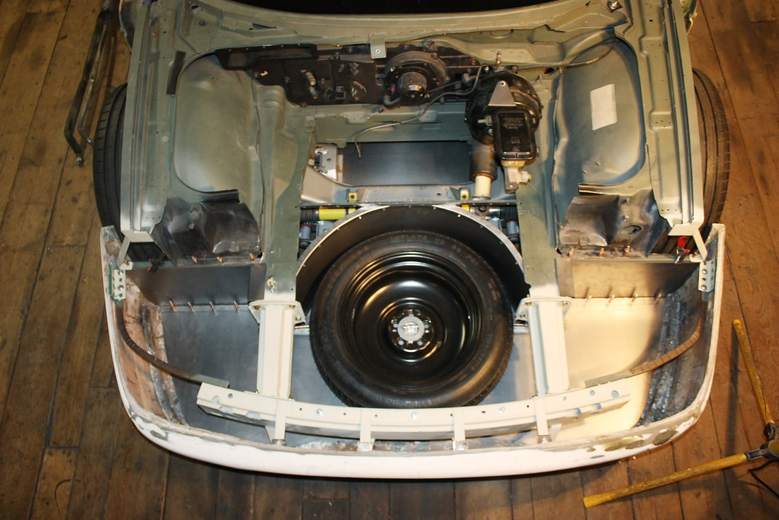 As luck would have it, while I was pilfering the salvage yard, I came across a late model Subaru Outback whose spare tire had been removed, but the foam-mounted jack kit was left behind. After checking the diameter, I found it would fit perfectly inside my spare tire rim. Not a bad find for an additional $20: 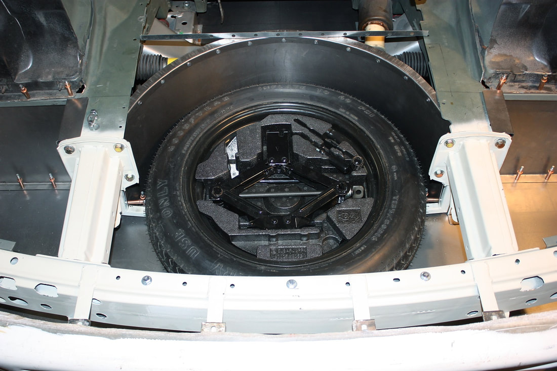 I may have to modify the top pad of the scissor jack for my frame, but that’s an easy task with a cut-off wheel and a welder. The next item on the agenda was to mount the battery. A basic Fiero hot-rodding trick is to move the 50 lb battery up front to help with better weight distribution. I didn’t have much choice since I was quickly running out of real estate in the engine bay. After a few measurements, it became clear the best place weight-wise, and for crash protection would be in the middle of the front suspension cross member. Some folks like to mount them ahead of the passenger front wheel, but that increases the polar moment of the car, and isn’t the best place in a front end collision. Besides, I have other plans for that space! 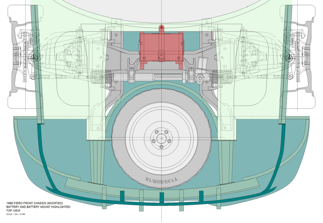 Space permitting, I wanted the amperage of the larger Cadillac battery (Group 78), which is one size up from the stock Fiero battery (Group 75): 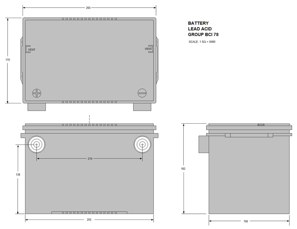 Luckily, there was just enough room between the steering rack mounts to accommodate the larger power pack. I would’ve also preferred a top post, rather than a foul-prone side-post battery, but the terminals would’ve ended up sticking into my planned luggage compartment floor: 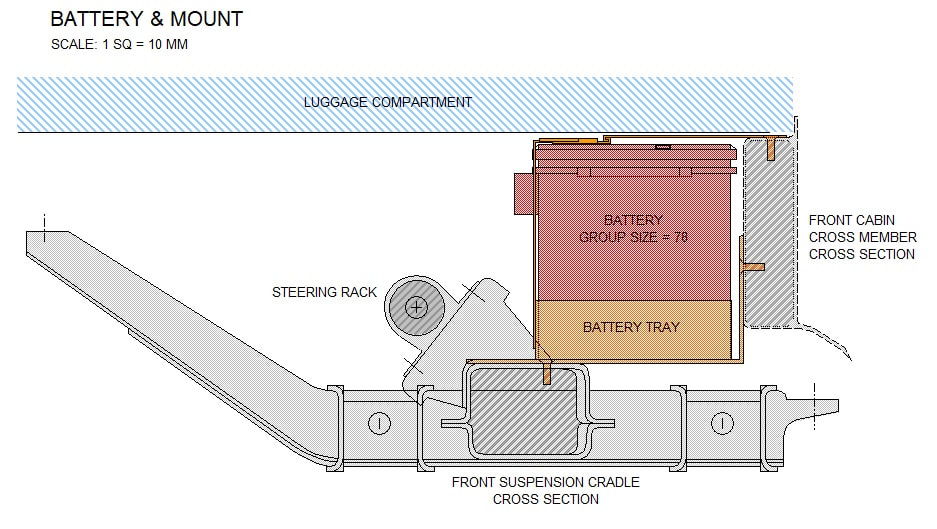 With my plan in hand, I set off to make the battery tray out of some 18 gauge steel to hold it in place laterally and longitudinally. After cutting out the basic box form, I folded the sides in my bench brake: 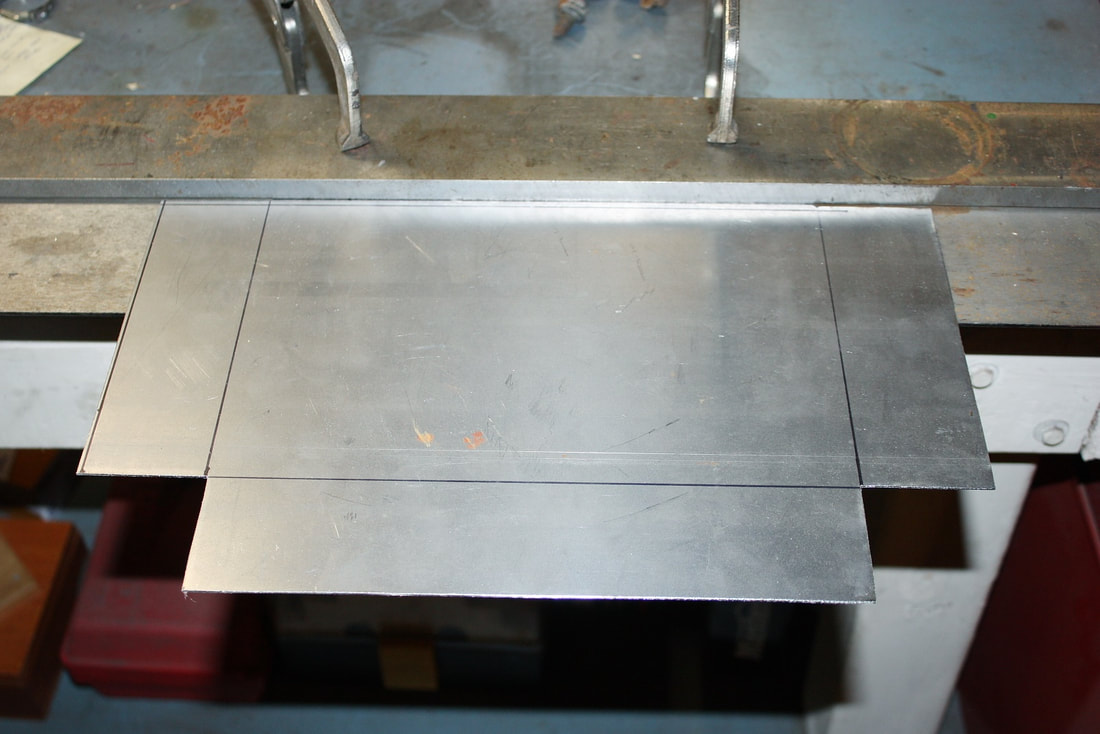 Then I zip-zapped the corners with my MIG welder: 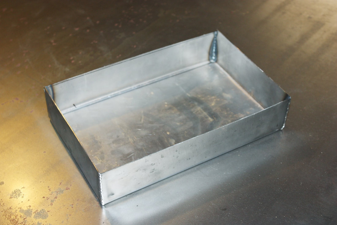 To support the battery tray, I bent a pair 1/8” x 1” flat steel bars into “L” brackets, drilled two countersunk holes in each, then drilled and tapped matching holes in the front suspension cross member, and the front cabin cross member to attach them to: 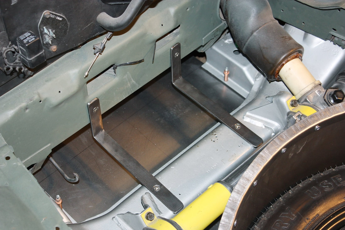 Then I clamped the battery tray to the supports, and welded the tray to them: 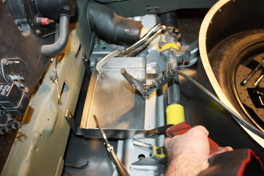 And voila! A tidy, low-CofG, safely protected battery. All that I needed more was an over-battery strap to keep it in place in the event of a roll-over: 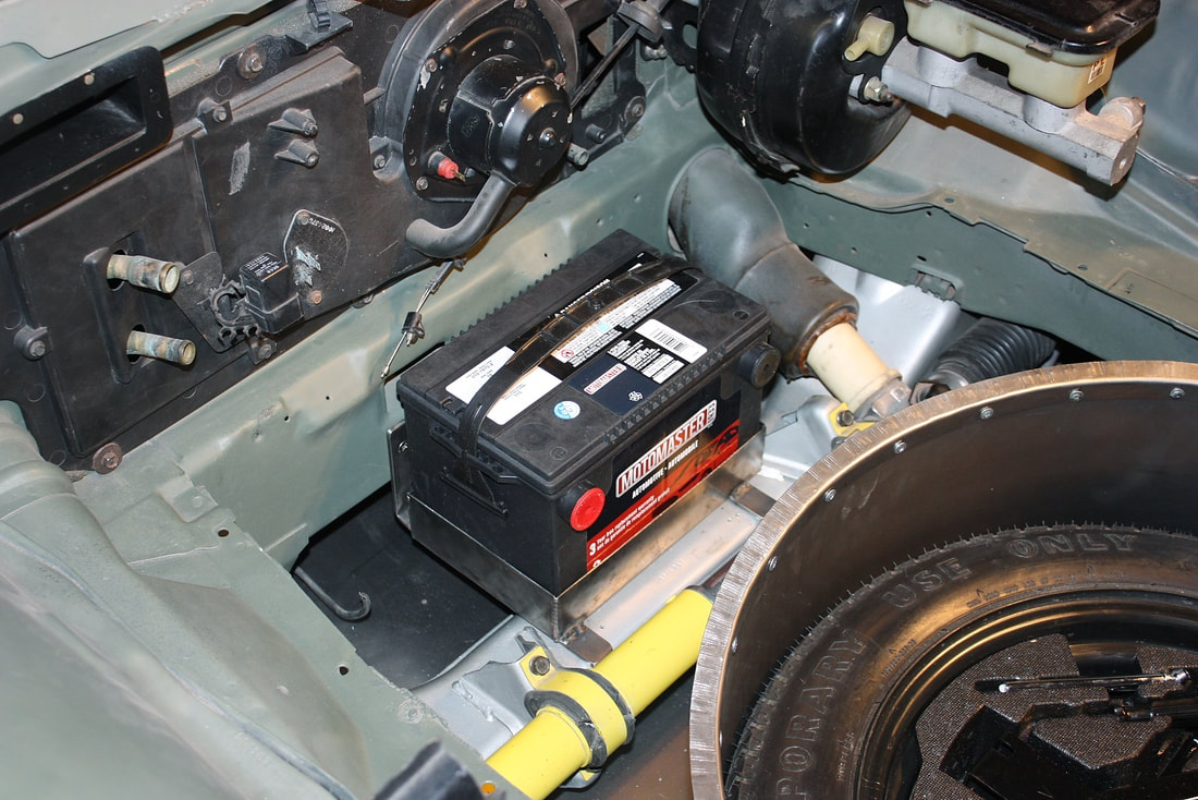 I scratched my head a bit before stumbling upon a neat little low profile butterfly latch in a drawer I keep all sorts of odds and sods: 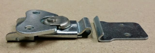 I riveted the latch to some 1-1/4” wide spring steel strapping, then riveted the lower end of the strapping to tray, while attaching the upper end to the cabin cross member with a single pivoting screw. To remove the battery, I undo the latch, and swing the upper strap out of the way: 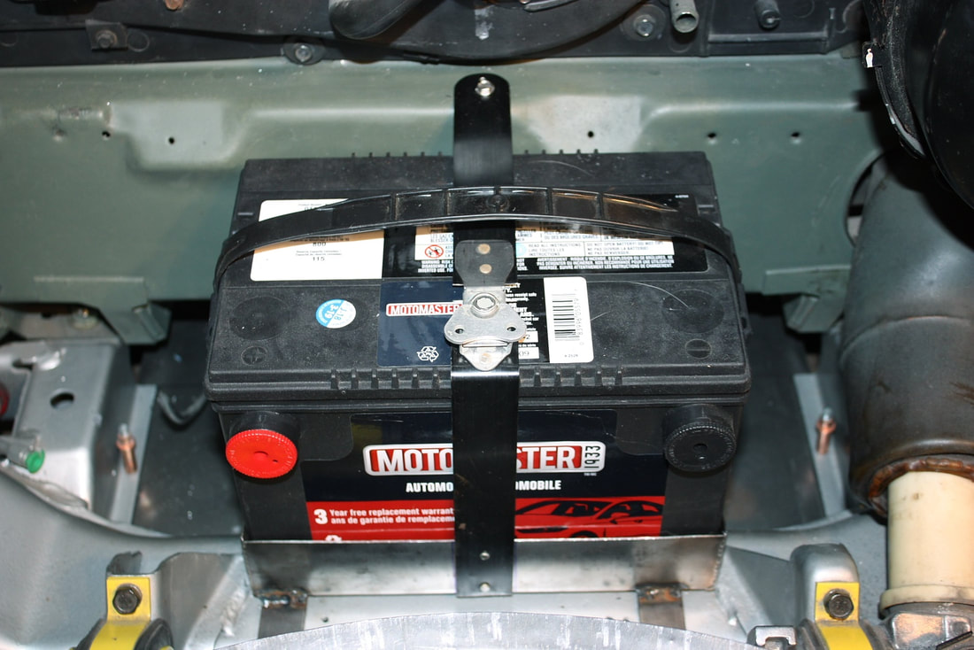 With the battery centered, there's still plenty of room on either side to pass the heater hoses and brake lines that head to the back end of the chassis. With the undertray prototyped in my last post, the next step to seal off the front compartment was to build the walls leading into the front wheel wells. From the last post: 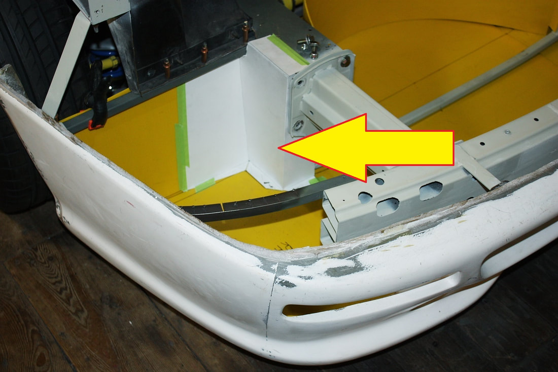 Luckily the left and right hand areas were symmetrical enough that I was able to use the same template for both sides. Once unfolded, I traced the template onto some more 22 gauge steel, and cut out the forms with a thin cut-off wheel: 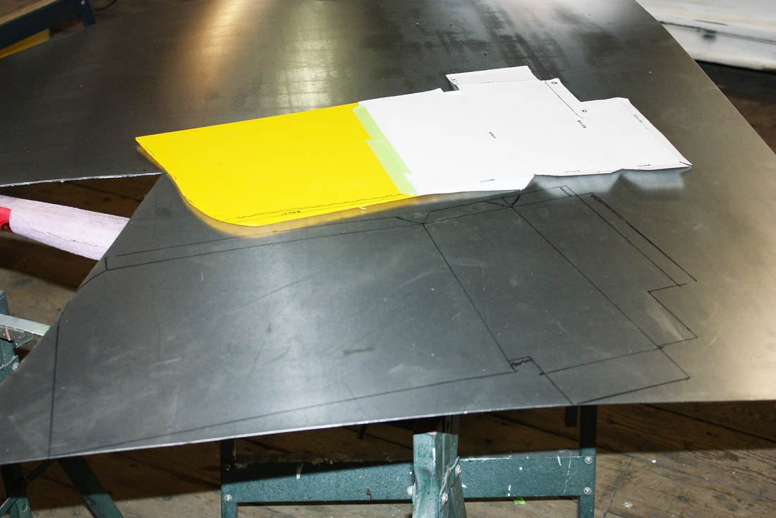 Next I needed to bend them into shape. I have a small, bench-top metal brake that comes in handy for light weight sheet bending: 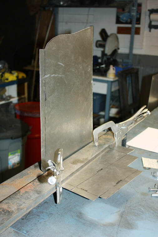 With careful planning, I was able to make all of the longer bends using the brake, and the shorter ones using some duck-billed Vise-grips, without boxing myself into a corner (pun intended!): 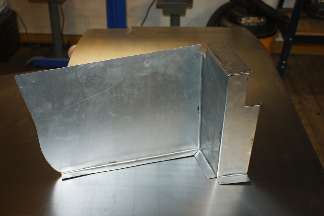 With a little fidgeting, I sealed off the front compartment from the wheel wells with my new forms. I was careful to make integral flanges to tie the pieces into the undertray, and the rest of the chassis: 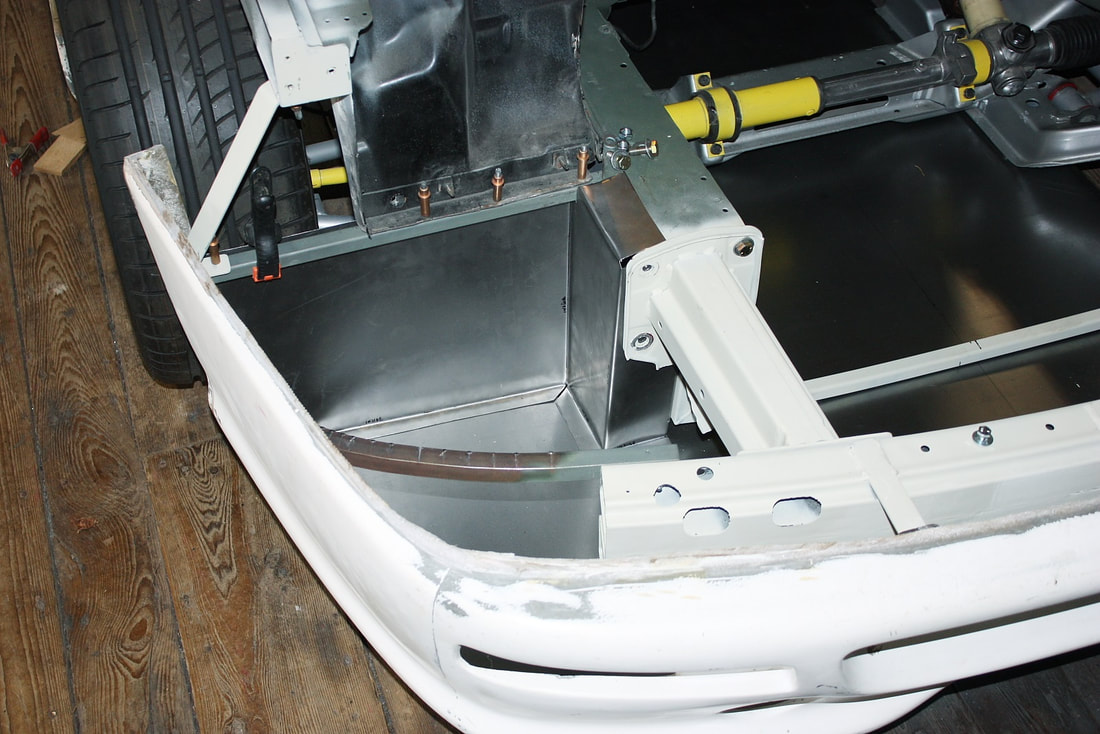 Here’s an overhead photo of both sides mocked up: 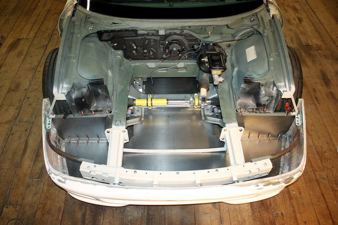 The spare tire well was considerably easier to make. I mocked up the template and took note of any minor changes needed: 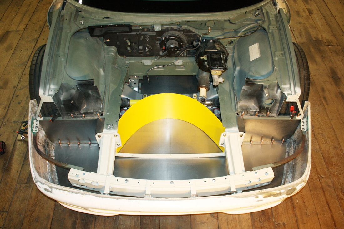 Then I unrolled it and traced it out on some more 22 gauge steel. I wanted the compartment to be made of steel for a couple reasons. The main one was to provide an extra measure of wheel containment in the event of a front end collision, but the wall will also serve as a stiffener for the lower undertray, and will help support the floor of the luggage compartment above it: 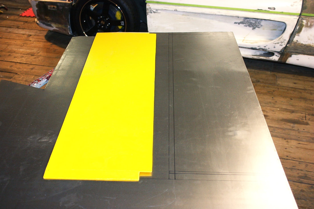 As with the wheel well separators, I planned extra material along the bottom to form a flange that could be fastened to the undertray. My 36” metal brake wasn't long enough to bend the flange so I popped over to the aviation museum where I’m the Avro Lancaster restoration team leader. There, I was able to bend the flange on the 48” finger brake. Volunteering over 1500 hours has its privileges! 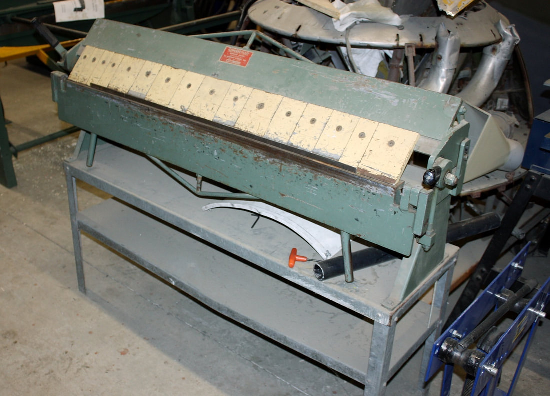 Once back at home, I used my shrinker to put a gentle curve into the flange. The shrinker has jaws that grab and bunch up a small amount of metal at a time allowing an easy way to make simple curved surfaces: 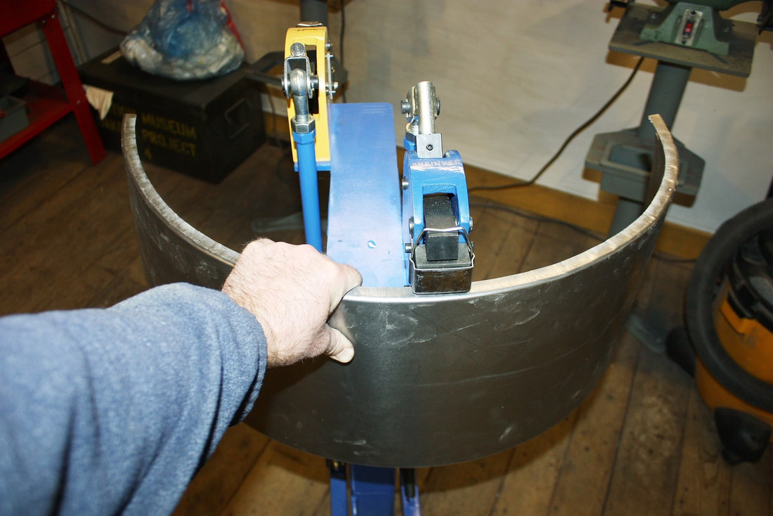 I had traced the curvature I wanted onto a large sheet of paper and kept comparing the actual piece to the desired shape until it was just right: 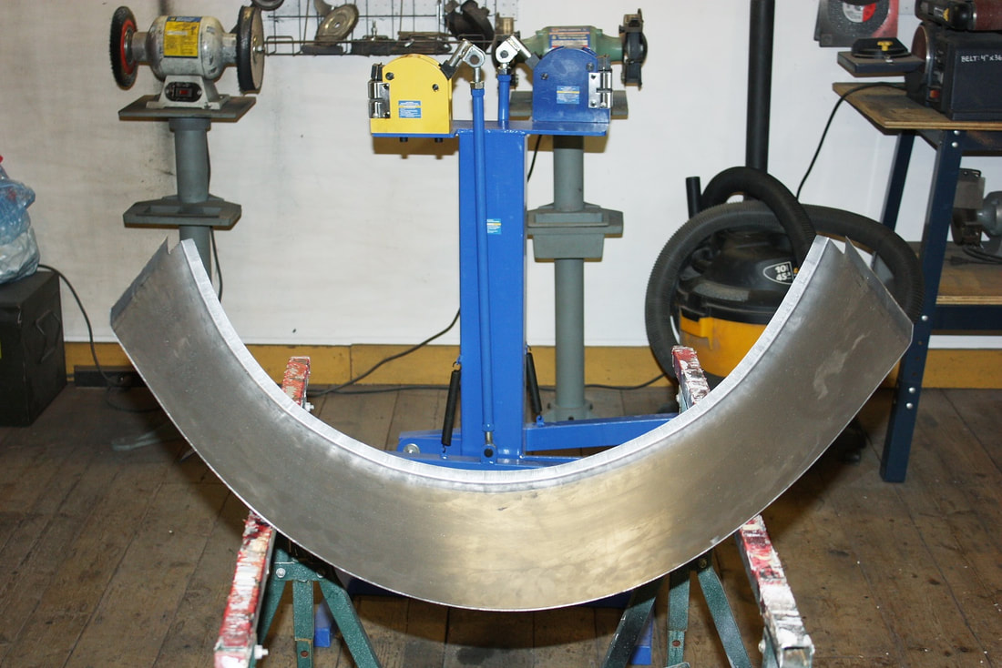 After a few tweaks, it fit like a glove between the two lower frame rails: 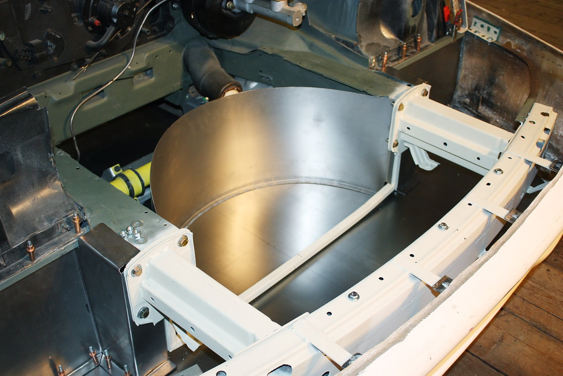 The last step was to form an upper flange. I wanted to kill two birds with one stone: force the proper shape along the top of the curved wall; and provide an upper attachment surface for wall to the luggage compartment floor that will sit above it later on. To make the flange I cut a 42” long x 1-1/2” wide strip of 22 gauge steel, then folded it in half, width-wise using the museum’s finger brake, and finally formed it using the “stretcher” half of my shrinker/stretcher: 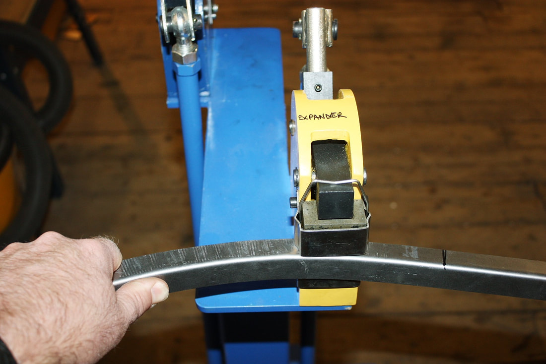 Using the same curvature template I made earlier, here’s what the upper flange looked like when I was done: 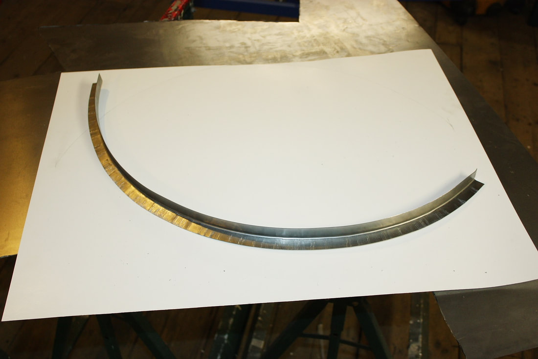 Installing it was a cinch. 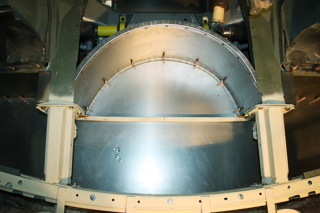 I'll deal with the rest of the spare tire well details when I buy an appropriate spare wheel and tire assembly. I’m currently scouring area salvage yards for a space-saver wheel with at least a 16” rim diameter, 5 x 100mm bolt hole circle, and a large enough offset to clear my 12” brakes. The ideal tire would also have an overall tire diameter of 25 inches. Subarus, late model VW Beetles, and Chrysler PT Cruiser’s are potential candidates. Stick around for more front compartment work in my next post. |

About Dave:A retired military aerospace engineer with nothing better to do. Chassis Topics
All
|
 RSS Feed
