I’ve already covered the radiator plumbing in an earlier post, so this one’s about completing the secondary coolant circuits, with a bonus bit on the Exhaust Gas Recirculation circuit.
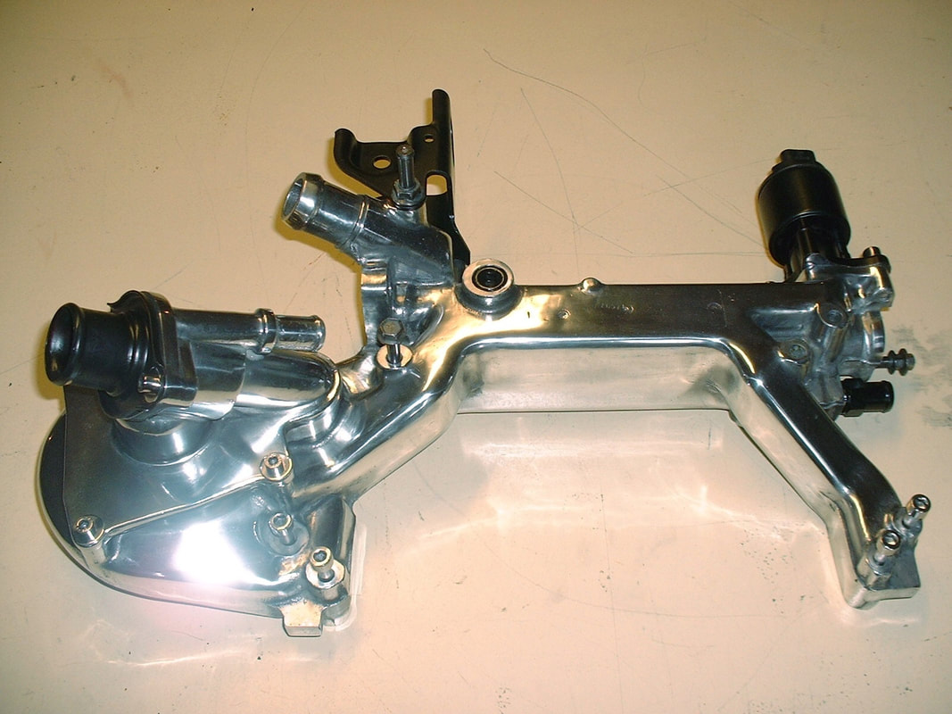
Gone are the days of the simple, input-output pump mounted to a small block Chevy. The Northstar’s water pump is mounted to a cast aluminum water manifold that has no fewer than nine water ports and three EGR ports:
I’ve already covered the radiator plumbing in an earlier post, so this one’s about completing the secondary coolant circuits, with a bonus bit on the Exhaust Gas Recirculation circuit.
Gone are the days of the simple, input-output pump mounted to a small block Chevy. The Northstar’s water pump is mounted to a cast aluminum water manifold that has no fewer than nine water ports and three EGR ports:
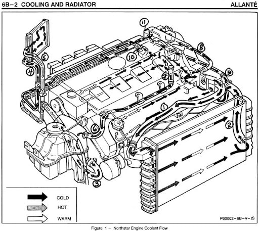
If that weren’t enough, there doesn’t seem to be a single, clear illustration on the entire Worldwide Web that shows how the manifold distributes water to each of the ports internally, what each of the ports are used for, nor how they’re routed to accomplish their task. This is the best the internet has to offer, and it’s completely incomprehensible at the water log:
If that weren’t enough, there doesn’t seem to be a single, clear illustration on the entire Worldwide Web that shows how the manifold distributes water to each of the ports internally, what each of the ports are used for, nor how they’re routed to accomplish their task. This is the best the internet has to offer, and it’s completely incomprehensible at the water log:
I needed something way better than this to know how to plumb the cooling circuits on my car. So after countless hours sorting through incomplete parts diagrams, partial descriptions of system operation, and sorting out conflicting opinions about whether the system is reverse flow or not, I’ve finally cobbled up this all-in-one flow diagram:
I needed something way better than this to know how to plumb the cooling circuits on my car. So after countless hours sorting through incomplete parts diagrams, partial descriptions of system operation, and sorting out conflicting opinions about whether the system is reverse flow or not, I’ve finally cobbled up this all-in-one flow diagram:
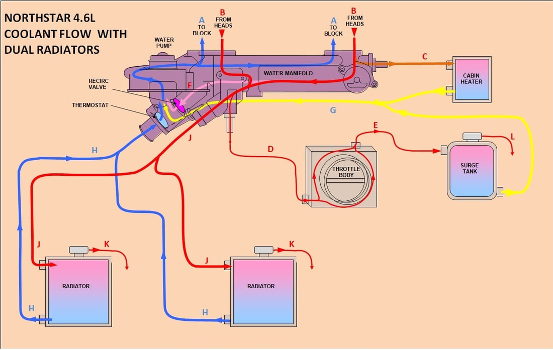
Bear with me as I describe the various circuits since they’re not completely intuitive even with a decent flow diagram. The two keys to understanding the flow through the water manifold is realizing the thermostat lets cold water into the engine, not hot water out like a SBC, and that there’s something new… a recirculation valve. I’ve labeled each of the circuits with a letter to help follow along (This description is mostly for my own benefit because every engineer knows that if you can’t explain something in simple terms, you don’t understand it yourself!):
Cold water leaves the pump and enters the engine block through two ports (A) whenever the pump is running. After circulating through the block it passes up through the heads and is returned to the water manifold through ports (B) in each cylinder head. If the water hasn’t reached normal operating temperature (195*F) the thermostat remains closed preventing the water from circulating to the radiators since the return circuit (H) is closed by the thermostat.
While the thermostat is closed, most of the warm water is forced to take path (F) which is internal to the manifold. It arrives at a spring-loaded recirculation valve which is pushed open by the water pressure created by the blocked flow to the radiators. The water passes through the recirculation valve, back to the pump inlet, and circulated through the block again until it reaches 195*F.
At 195*F the thermostat opens, removing the restriction on the radiator return circuit (H) allowing coolant to flow freely to the radiators via circuit J, and back to the pump inlet via circuit H. The redirected flow relieves the water manifold internal pressure so the spring loaded recirculation valve closes blocking circuit F, forcing most of the water down circuit J to the radiators.
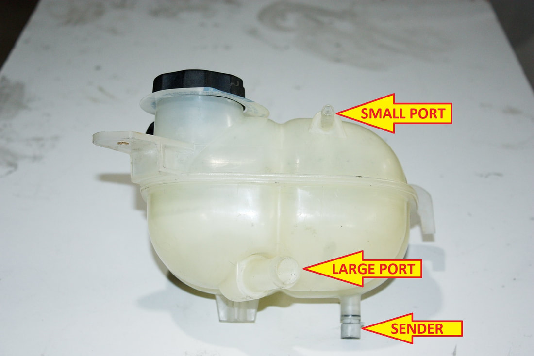
Some hot water is directed to the in-cabin heater core (C), and to the throttle body heater circuit (D) at all times. Once cooled by the throttle body, water is returned (E) to the surge tank. Cold water is drawn at all times from both the surge tank and the heater core back into the pump through circuit G which bypasses the thermostat and the recirculation valve entirely, allowing continuous flow.
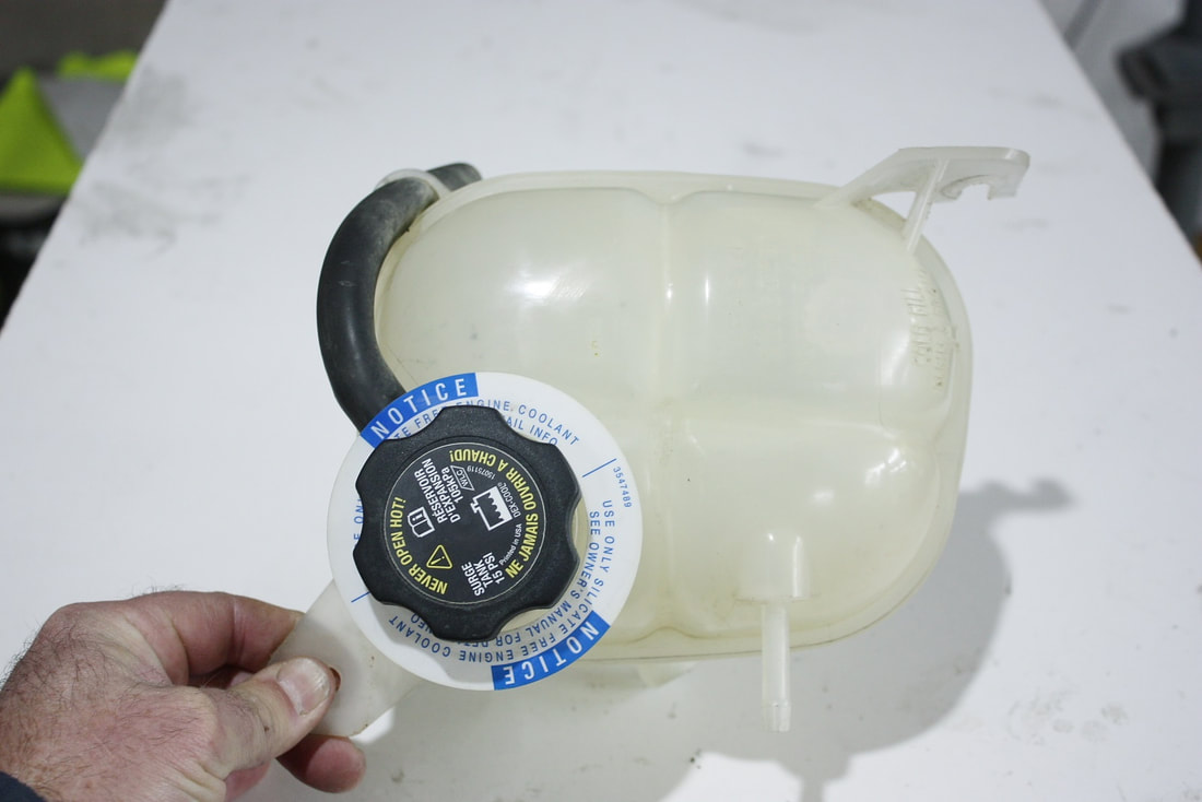
System pressure is maintained below 15 psi to protect the radiators and heater core, which are the weakest link in the system. A spring-loaded pressure relief cap on the surge tank allows the steam at the top of the surge tank to be vented overboard (L) if the pressure exceeds 15 psi.
In the event the surge tank pressure cap fails to relieve an over-pressure situation, each radiator has its own pressure relief cap set 1 psi higher than the surge tank cap. These caps will vent liquid coolant overboard (K) until the system pressure drops below 16 psi.
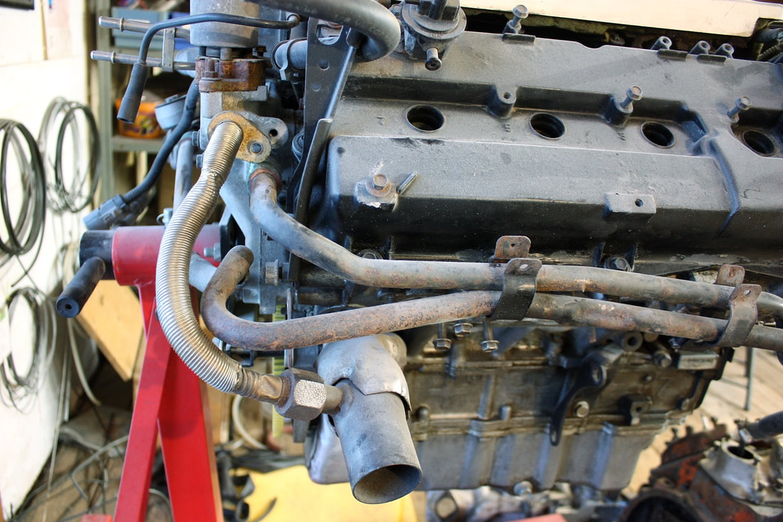
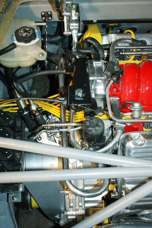
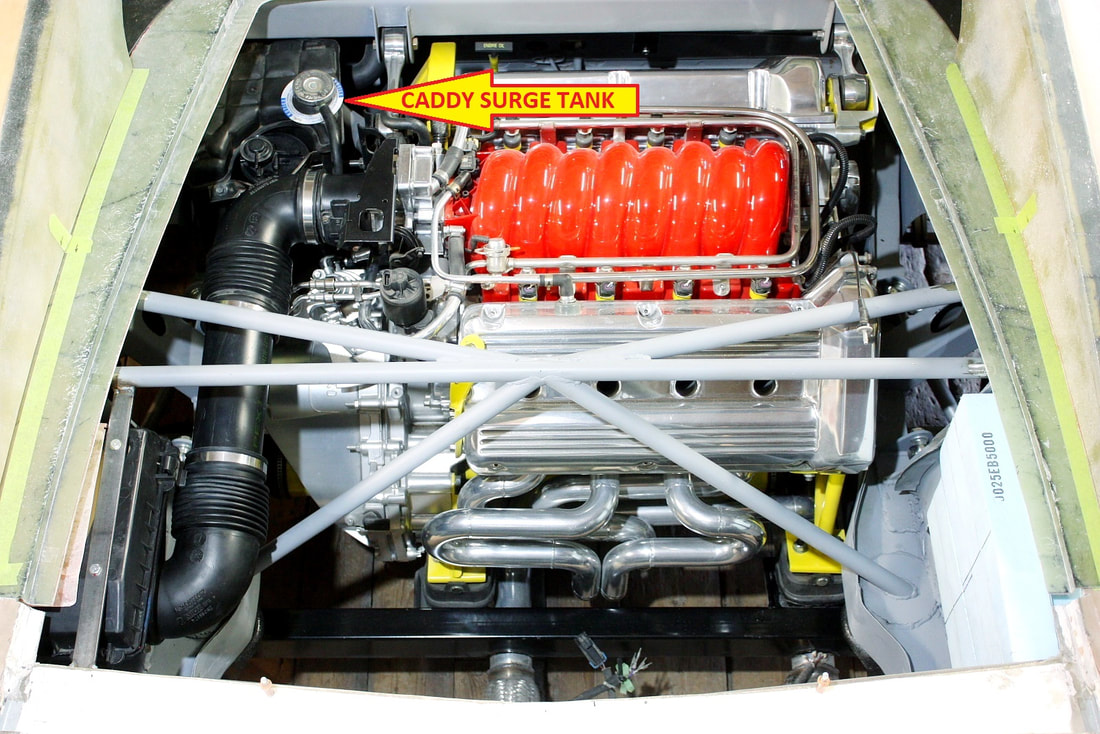
And with that, I was finally able to make some sense of what plumbing I was missing, which port connected to what appliance, and devise a plan to fit it all in the engine bay. One thing was certain, I didn’t want to reuse the ugly OEM steel heater lines. They leave the water manifold, run backwards down the left side of the engine, then across the entire length of the aft valve cover. They’re hidden in the Caddy engine bay because the aft head is against the firewall. Not so in the Fiero engine bay:
Bear with me as I describe the various circuits since they’re not completely intuitive even with a decent flow diagram. The two keys to understanding the flow through the water manifold is realizing the thermostat lets cold water into the engine, not hot water out like a SBC, and that there’s something new… a recirculation valve. I’ve labeled each of the circuits with a letter to help follow along (This description is mostly for my own benefit because every engineer knows that if you can’t explain something in simple terms, you don’t understand it yourself!):
Cold water leaves the pump and enters the engine block through two ports (A) whenever the pump is running. After circulating through the block it passes up through the heads and is returned to the water manifold through ports (B) in each cylinder head. If the water hasn’t reached normal operating temperature (195*F) the thermostat remains closed preventing the water from circulating to the radiators since the return circuit (H) is closed by the thermostat.
While the thermostat is closed, most of the warm water is forced to take path (F) which is internal to the manifold. It arrives at a spring-loaded recirculation valve which is pushed open by the water pressure created by the blocked flow to the radiators. The water passes through the recirculation valve, back to the pump inlet, and circulated through the block again until it reaches 195*F.
At 195*F the thermostat opens, removing the restriction on the radiator return circuit (H) allowing coolant to flow freely to the radiators via circuit J, and back to the pump inlet via circuit H. The redirected flow relieves the water manifold internal pressure so the spring loaded recirculation valve closes blocking circuit F, forcing most of the water down circuit J to the radiators.
Some hot water is directed to the in-cabin heater core (C), and to the throttle body heater circuit (D) at all times. Once cooled by the throttle body, water is returned (E) to the surge tank. Cold water is drawn at all times from both the surge tank and the heater core back into the pump through circuit G which bypasses the thermostat and the recirculation valve entirely, allowing continuous flow.
System pressure is maintained below 15 psi to protect the radiators and heater core, which are the weakest link in the system. A spring-loaded pressure relief cap on the surge tank allows the steam at the top of the surge tank to be vented overboard (L) if the pressure exceeds 15 psi.
In the event the surge tank pressure cap fails to relieve an over-pressure situation, each radiator has its own pressure relief cap set 1 psi higher than the surge tank cap. These caps will vent liquid coolant overboard (K) until the system pressure drops below 16 psi.
And with that, I was finally able to make some sense of what plumbing I was missing, which port connected to what appliance, and devise a plan to fit it all in the engine bay. One thing was certain, I didn’t want to reuse the ugly OEM steel heater lines. They leave the water manifold, run backwards down the left side of the engine, then across the entire length of the aft valve cover. They’re hidden in the Caddy engine bay because the aft head is against the firewall. Not so in the Fiero engine bay:
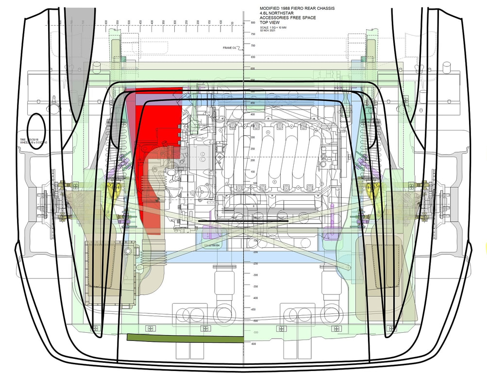
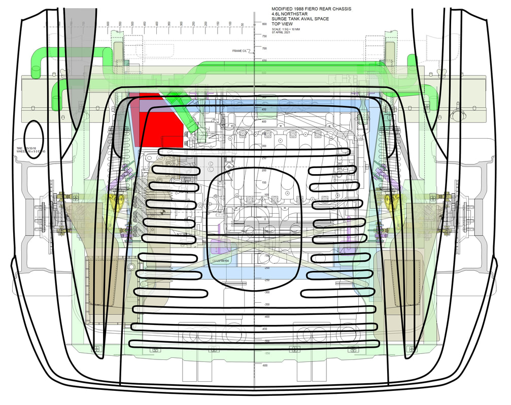
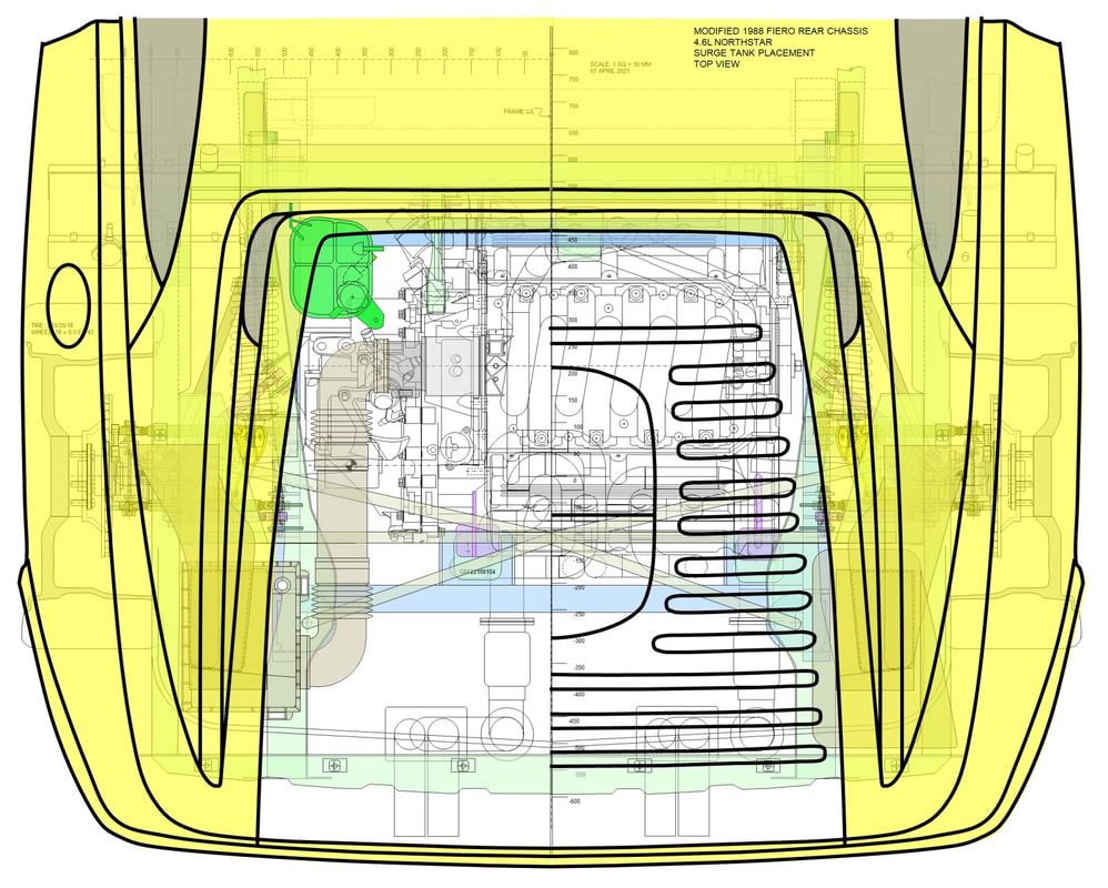
I didn’t want any more of the heater and surge tank plumbing to be visible than was absolutely necessary, but the orientation of the water manifold ports make it a difficult task. I would need to make a few tight 180+ degree turns in the plumbing right out of the manifold to accomplish this. I used my top view drawing of the engine bay to help plan the layout of the tubing, which I colour-coded the same as the first drawing above to help identify the circuits. I left out the throttle body lines for clarity:
I didn’t want any more of the heater and surge tank plumbing to be visible than was absolutely necessary, but the orientation of the water manifold ports make it a difficult task. I would need to make a few tight 180+ degree turns in the plumbing right out of the manifold to accomplish this. I used my top view drawing of the engine bay to help plan the layout of the tubing, which I colour-coded the same as the first drawing above to help identify the circuits. I left out the throttle body lines for clarity:
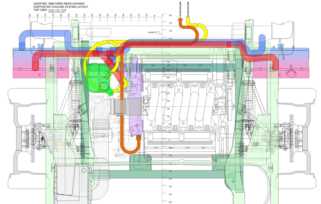
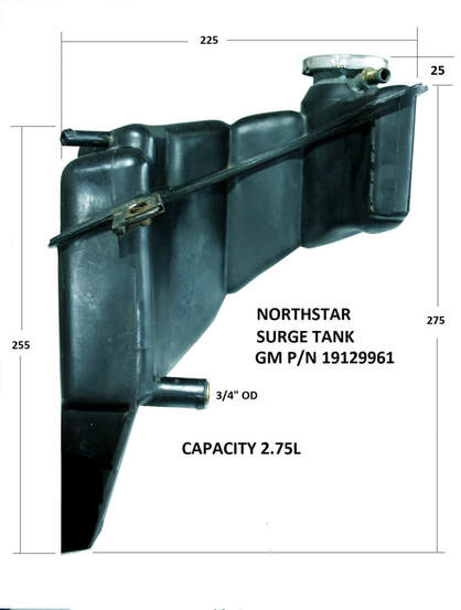
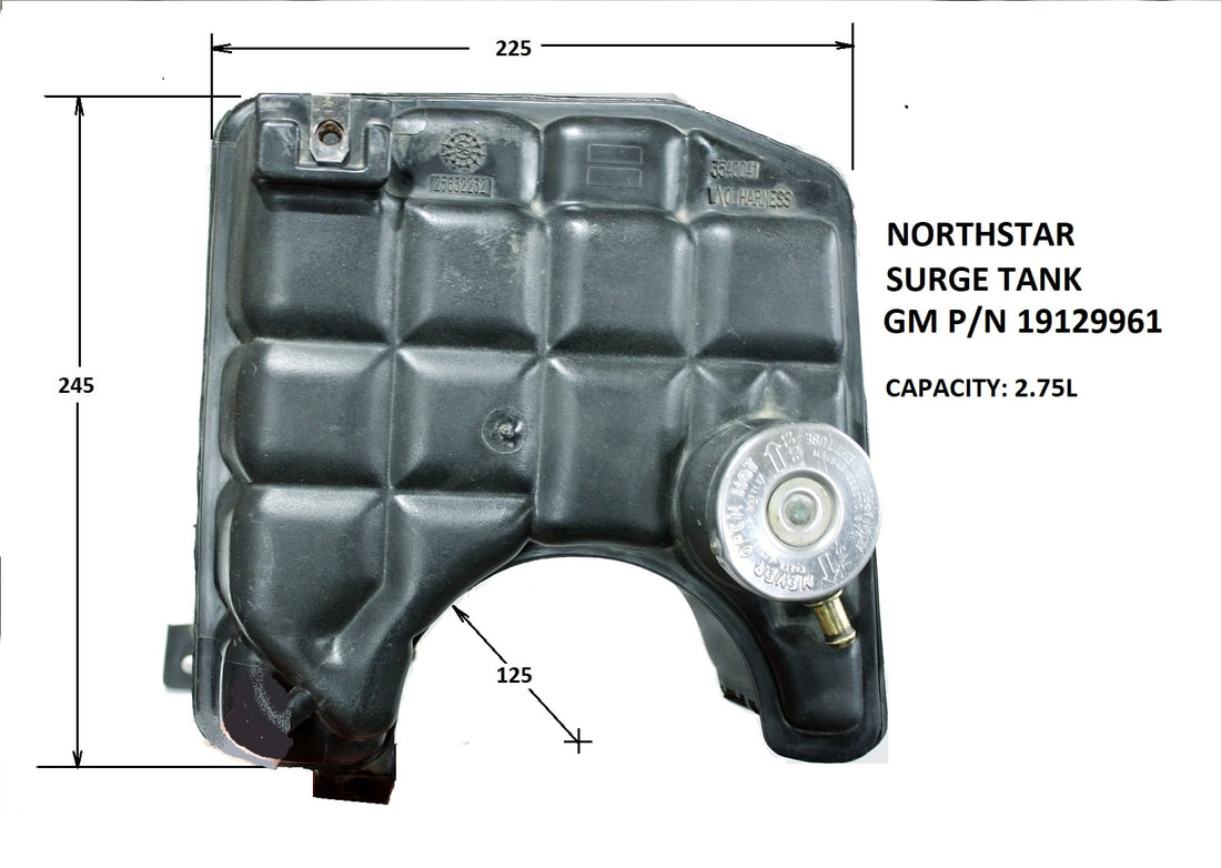
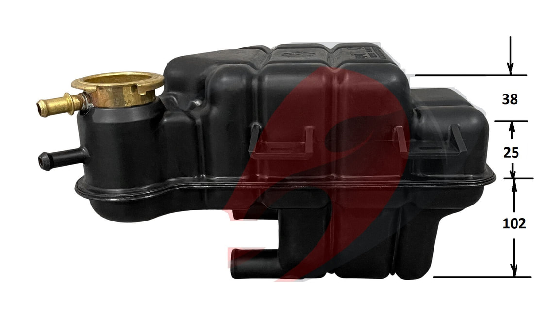
The yellow (or cold water return) circuit was particularly challenging with a 330 degree turn being the only way to get the plumbing headed in the right direction. To clear the engine, I needed a tight 90 degree elbow right out of the water manifold with the rest being made up of gently looped hose. The surge tank’s large port, which also connects to this circuit, was also in a less-than-ideal orientation. The large loop gave me the room to connect the surge tank with a gently curved hose and a Y connector. From the Y onwards, the rest of the yellow circuit would be aluminum tubing.
The orange (or hot water) circuit required a 180 degree U-bend out of the manifold, followed by a section of straight aluminum tubing heading toward the front firewall, coupled to a rubber 90 degree bend, then a straight run along the firewall.
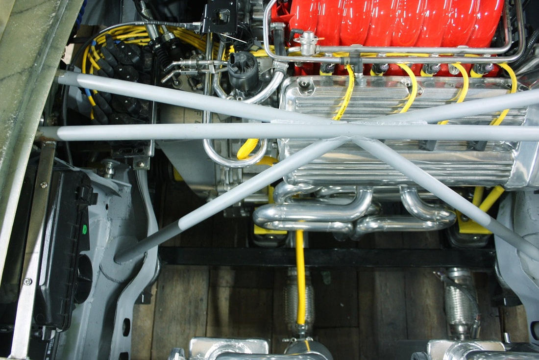
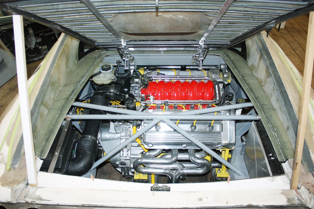
Here’s the rear view of the coolant circuits:
The yellow (or cold water return) circuit was particularly challenging with a 330 degree turn being the only way to get the plumbing headed in the right direction. To clear the engine, I needed a tight 90 degree elbow right out of the water manifold with the rest being made up of gently looped hose. The surge tank’s large port, which also connects to this circuit, was also in a less-than-ideal orientation. The large loop gave me the room to connect the surge tank with a gently curved hose and a Y connector. From the Y onwards, the rest of the yellow circuit would be aluminum tubing.
The orange (or hot water) circuit required a 180 degree U-bend out of the manifold, followed by a section of straight aluminum tubing heading toward the front firewall, coupled to a rubber 90 degree bend, then a straight run along the firewall.
Here’s the rear view of the coolant circuits:
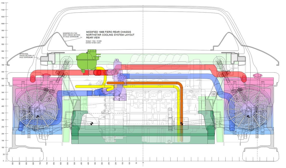
Here it’s clear the heater circuits have to drop back down to the bottom of the car after traversing the firewall. That’s because the stock Fiero lines coming from the heater core run under the center of the chassis.
So with a physical plan in one hand, and a good understanding of what to do, I moved on to fabrication. I didn’t document the entire layout in photos simply because the drawings show it far more clearly than pictures could ever do in the dark, tight space between the firewall and engine.
I will cover one aspect in more detail though, since it very much tried my patience. When I started work on the orange circuit, I needed to source a pre-formed 180 degree U-bend rubber hose to connect to the manifold’s stock barbed fitting:
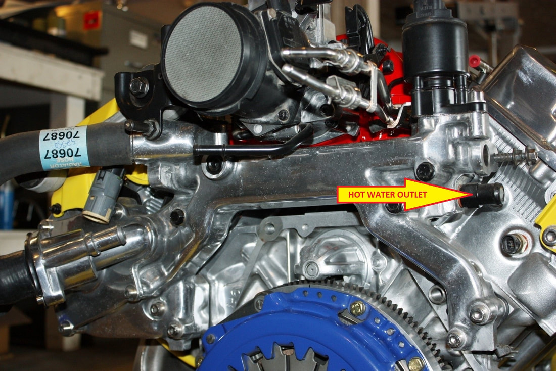
It had to be pre-formed otherwise the tight bend radius would have caused it to collapse. Easy-peasy. That was until the current supply-chain problems due to COVID-19 stopped me in my tracks. At the time of this post, there wasn’t a single ¾” ID rubber or silicone U-bend hose available on any shelf, anywhere. Period. Nor could any retailer predict when they would have them in stock.
So I devised Plan B, which was to replace the barbed fitting in the manifold with a male AN-12 (3/4” diameter) adapter and a matching 180 degree female AN-12 fitting like this:
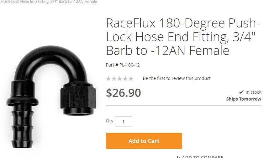
But once again I hit a show-stopper: the bend radius on every one of these style fittings was too tight. I needed a 2.5” bend radius to clear the engine when every fitting I could find had a 1.5” radius.
On to Plan C, which turned out to be the winning solution, but it wasn’t without its own setbacks. I bought some aluminum tubing to bend it to suit my exact needs. Then I searched every machine shop, hydraulic line shop, and refrigeration shop in the land for a tube bender able to bend ¾” tubing, to no avail. So what do you do when the success of 13 years labour fall on being unable to find a U-bent tube? You begrudgingly build your own bender:
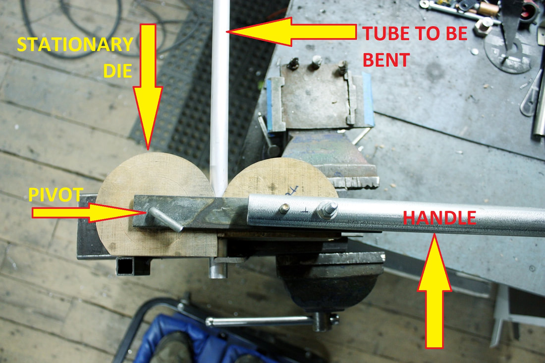
I cut some semi-circular quadrants from some 2” thick hardwood I had laying around, then routered a ¾” semi-circular groove in their circumferences to make dies of each. I pinned the stationary die’s center to a stout steel base, and attached the other to a long handle pivoted at the center of the first die. Then it was a simple matter of inserting the tube between the dies and walking one die around the other:
I cut some semi-circular quadrants from some 2” thick hardwood I had laying around, then routered a ¾” semi-circular groove in their circumferences to make dies of each. I pinned the stationary die’s center to a stout steel base, and attached the other to a long handle pivoted at the center of the first die. Then it was a simple matter of inserting the tube between the dies and walking one die around the other:
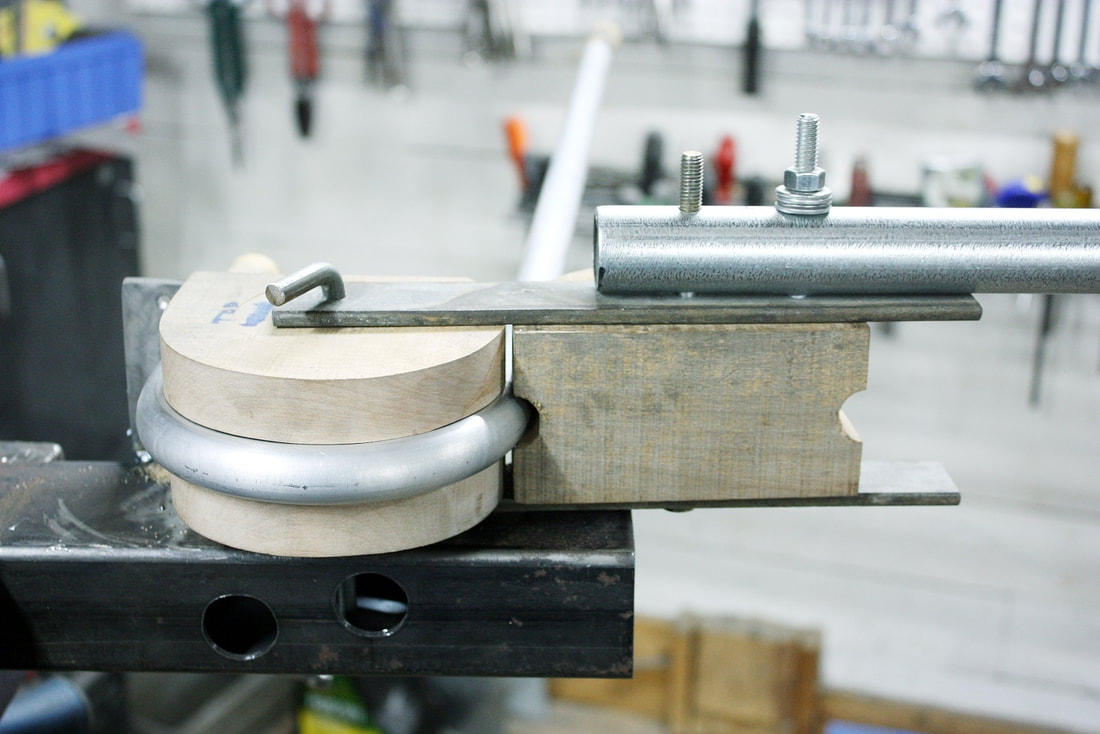
To keep the inner wall of the tube from crimping and the outer wall from collapsing, I tightly packed the tube full of sand and plugged both ends. It worked like a charm, though it took much more work than having been able to simply order a rubber hose:
To keep the inner wall of the tube from crimping and the outer wall from collapsing, I tightly packed the tube full of sand and plugged both ends. It worked like a charm, though it took much more work than having been able to simply order a rubber hose:
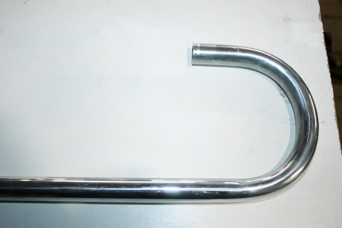
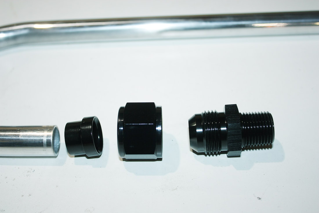
To mate the tube to the water manifold, I could’ve used a straight rubber union, but I decided to spruce it up a bit since it would be front and center. First, I polished the tube, then slipped an AN-12 tube nut and sleeve on it, and flared the end with a 37 degree flaring tool. It would then mate with the male ¾” NPT x male AN-12 adapter shown here:
To mate the tube to the water manifold, I could’ve used a straight rubber union, but I decided to spruce it up a bit since it would be front and center. First, I polished the tube, then slipped an AN-12 tube nut and sleeve on it, and flared the end with a 37 degree flaring tool. It would then mate with the male ¾” NPT x male AN-12 adapter shown here:
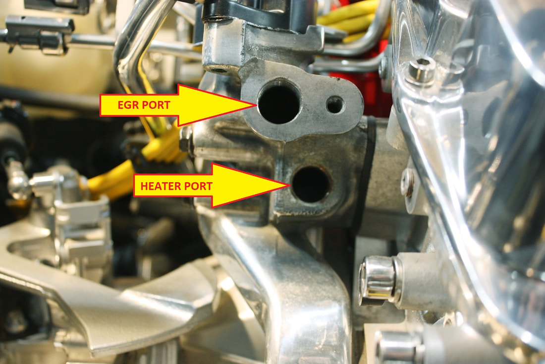
At this point I decided it would be wise not to complete the heater circuit without first considering the impact of the exhaust gas recirculation (EGR) plumbing since it was in virtually the same location as the heater tube:
At this point I decided it would be wise not to complete the heater circuit without first considering the impact of the exhaust gas recirculation (EGR) plumbing since it was in virtually the same location as the heater tube:
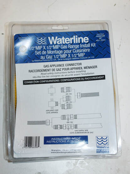
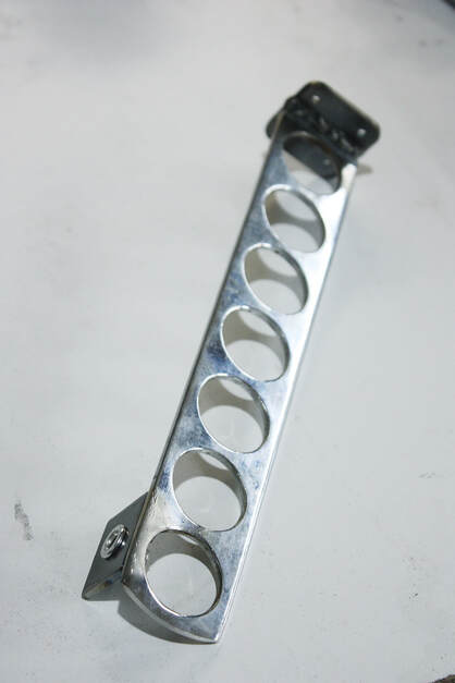
The trouble with the stock EGR tube was that it was far too short to meet up with my exhaust collectors, so a custom, stainless steel flexible tube was needed. I found the perfect source for the corrugated stainless steel tubing (CSST) at a propane appliance store:
The trouble with the stock EGR tube was that it was far too short to meet up with my exhaust collectors, so a custom, stainless steel flexible tube was needed. I found the perfect source for the corrugated stainless steel tubing (CSST) at a propane appliance store:
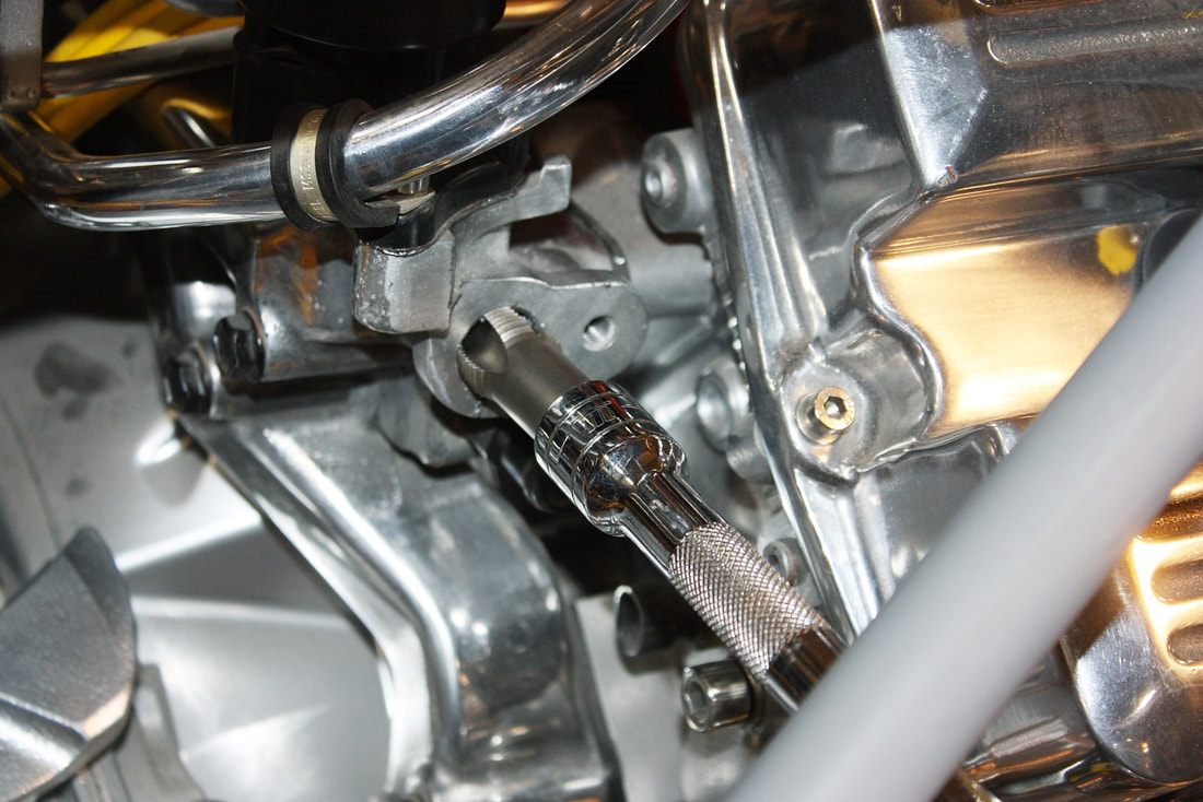
One thing to be noted about propane gas lines, is that they have 45 degree flared fittings versus 37 degree AN-style fittings. They can’t be interchanged, and to prevent unsuspecting DIY’ers from trying to mate the two, the fittings also have different thread pitches. Luckily the propane lines come with adapters that mate with standard NPT fittings so all I needed to do was tap the existing EGR port on the water manifold like so:
One thing to be noted about propane gas lines, is that they have 45 degree flared fittings versus 37 degree AN-style fittings. They can’t be interchanged, and to prevent unsuspecting DIY’ers from trying to mate the two, the fittings also have different thread pitches. Luckily the propane lines come with adapters that mate with standard NPT fittings so all I needed to do was tap the existing EGR port on the water manifold like so:
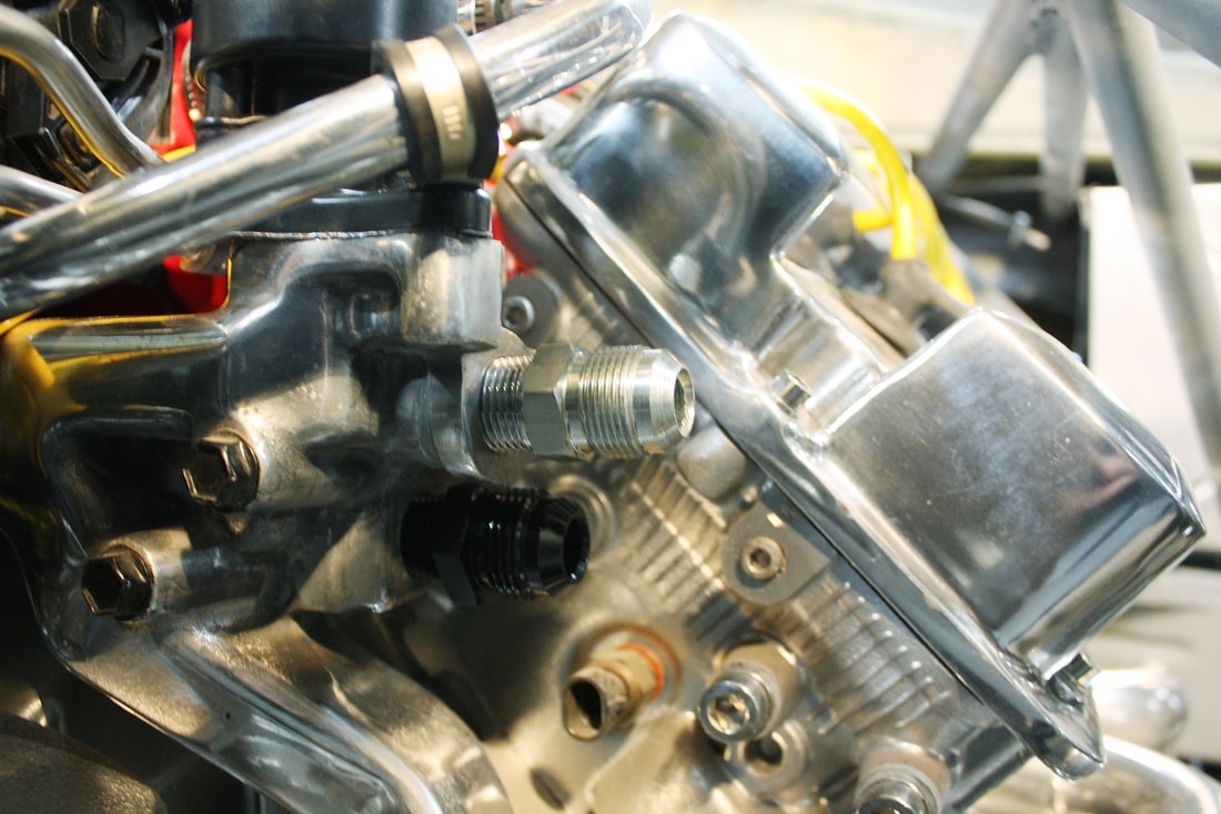
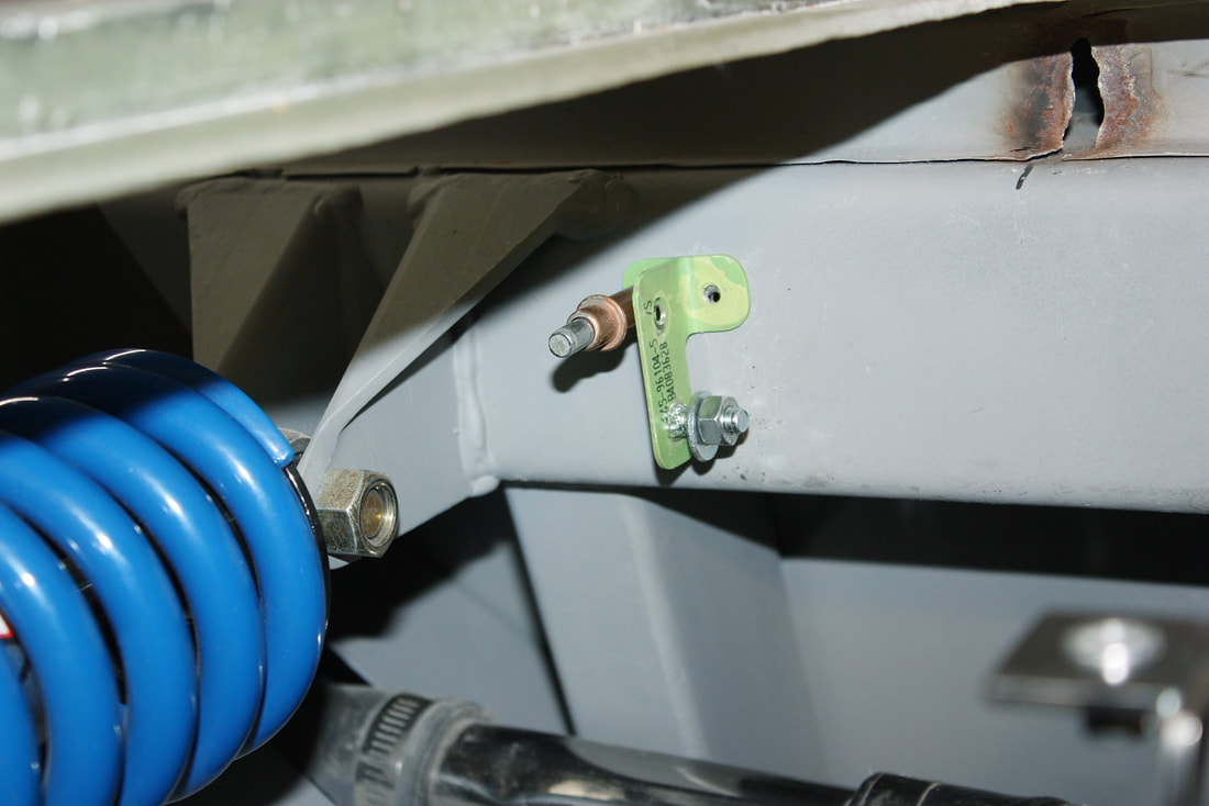
Then I could screw in both the water (black) and EGR (nickel) adapters needed to anchor the plumbing for each system to the manifold:
Then I could screw in both the water (black) and EGR (nickel) adapters needed to anchor the plumbing for each system to the manifold:
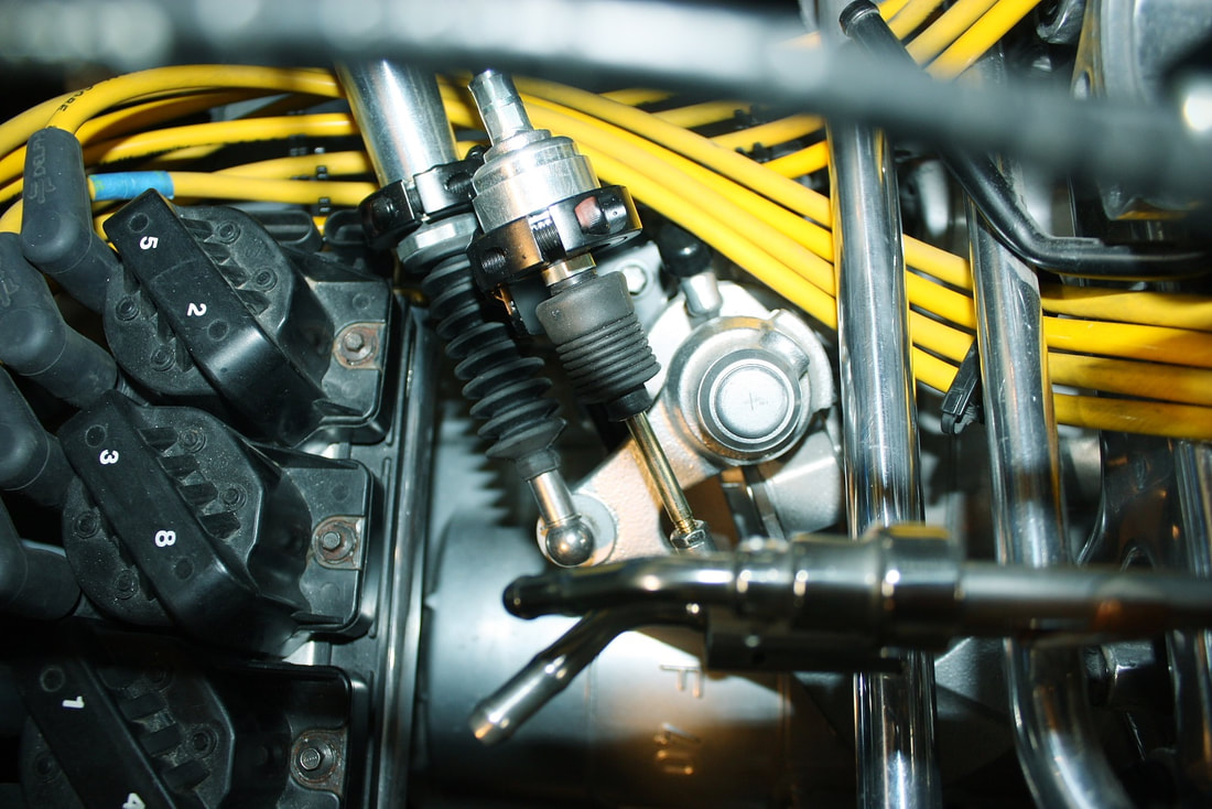
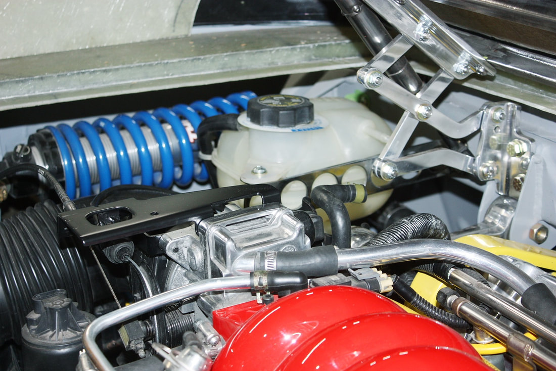
First up was the inflexible water tube I just bent. It’s the lower one in the next photo, with the upper one being the brake booster vacuum line. From this shot it’s easy to see why I needed a specific radius for the water line. Not too big, not too small:
First up was the inflexible water tube I just bent. It’s the lower one in the next photo, with the upper one being the brake booster vacuum line. From this shot it’s easy to see why I needed a specific radius for the water line. Not too big, not too small:
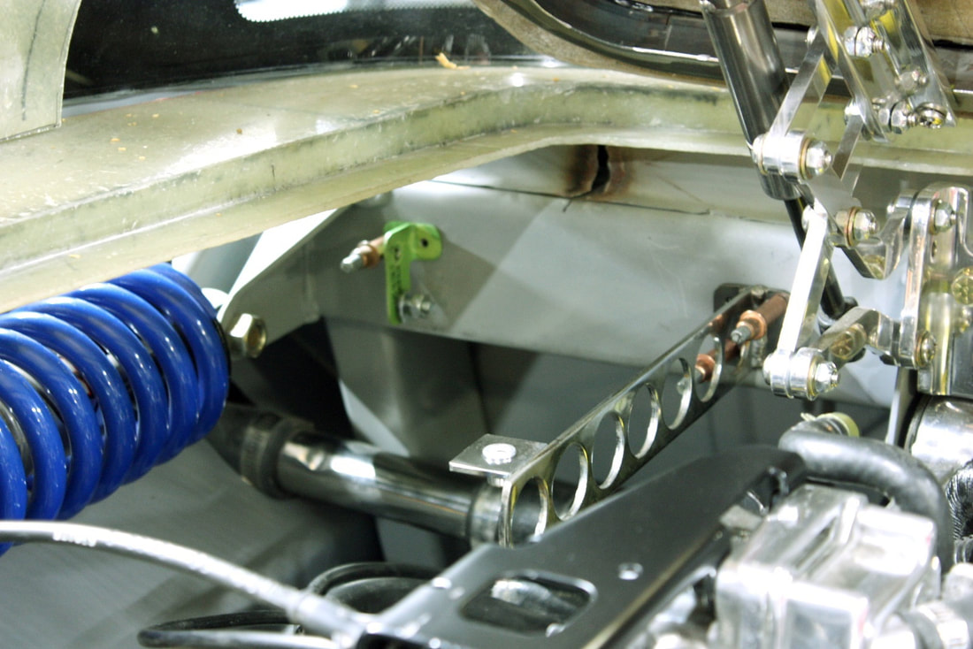
It had to squeeze between the brake booster line and the shifter quadrant. Here’s a close up of the clearances involved:
It had to squeeze between the brake booster line and the shifter quadrant. Here’s a close up of the clearances involved:
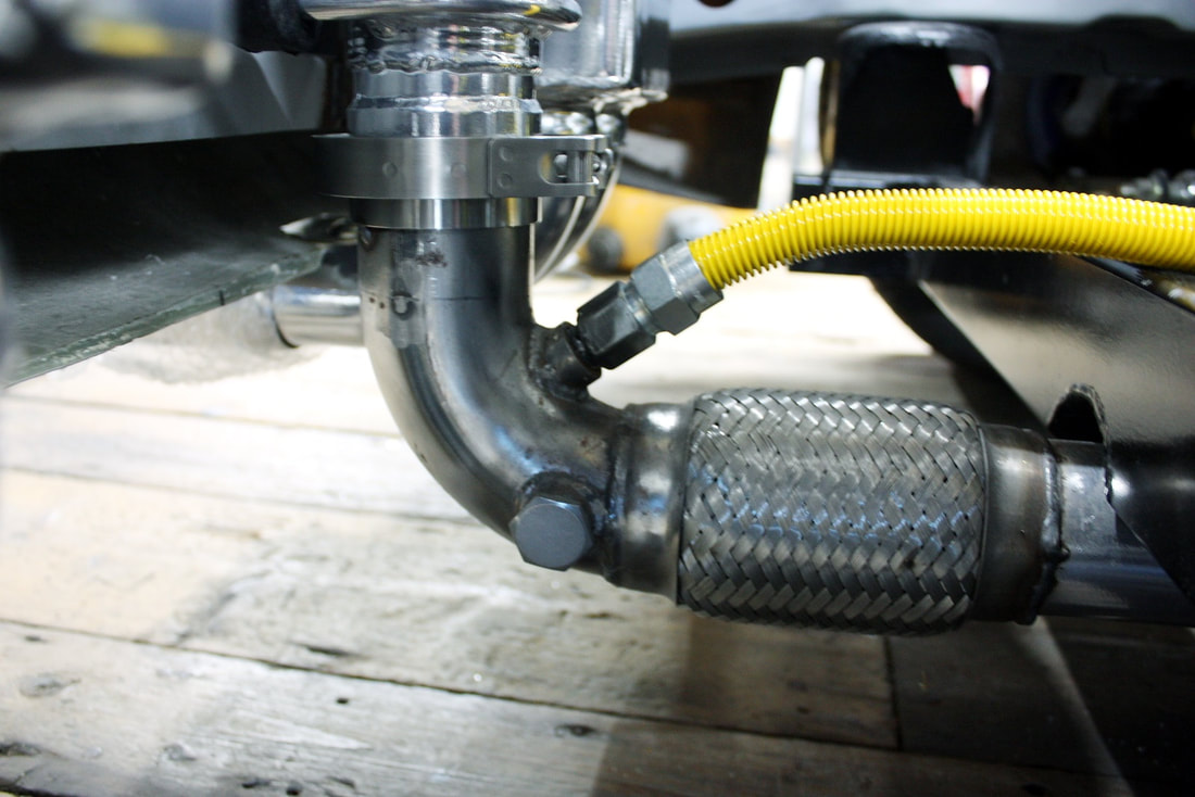
Next, I connected the flexible EGR tube and snaked it inside the heater tube radius, and behind the headers to exit next to the left hand exhaust collector:
Next, I connected the flexible EGR tube and snaked it inside the heater tube radius, and behind the headers to exit next to the left hand exhaust collector:
I left the yellow insulation on the stainless EGR tubing so it would show better in photos, but I intend to remove it before firing up the engine.
To mate the other end of the EGR tube to the collector, I chose to use one of the six O2 sensor ports I installed in the exhaust system:
I left the yellow insulation on the stainless EGR tubing so it would show better in photos, but I intend to remove it before firing up the engine.
To mate the other end of the EGR tube to the collector, I chose to use one of the six O2 sensor ports I installed in the exhaust system:
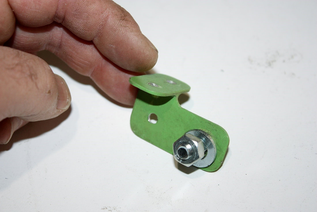
I had to get creative to connect the flex line to the O2 port since the port is metric and the flex line adapter was pipe thread on one end and unique gas line flare on the other. So I bought an M18 x 1.5 metric bolt that fit the O2 bung, cut the head off, drilled the threaded portion hollow, then welded it to the adapter in place of the NPT threaded section after I cut it off. Everything simply unscrews and I could easily swap the flex line to any other O2 port if needed.
That's it for this series of Odds & Sods posts, though I might need another one later on if body work starts to get too boring. Next up: more body work!
 RSS Feed
