Back in Post #156 my main concern was that I still had a number of components to fit into the engine bay and only a small corner of free-space to install them all. I fitted the ignition coils, transmission shifter cables, and throttle and cruise cables first since these were things that had virtually no other place they could be installed. This post is about the compromise I had to make to fit a coolant surge tank in a much smaller area after all the essential stuff had been added into the front corner of the engine bay.
First, why a pressurized surge tank? The simple answer is that it does two things a common reservoir doesn’t: it effectively increases the amount of coolant in the system by maintaining all of it in circulation at all times and; it also is more environmentally friendly because it doesn’t allow ethylene glycol vapour to be released into the atmosphere under normal conditions.
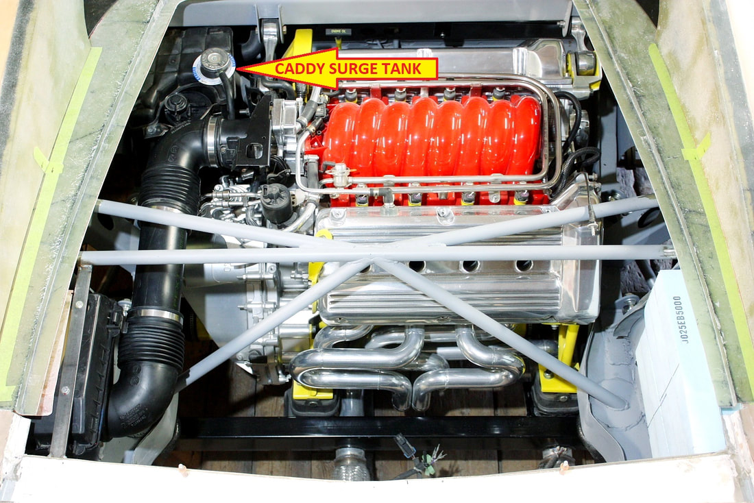
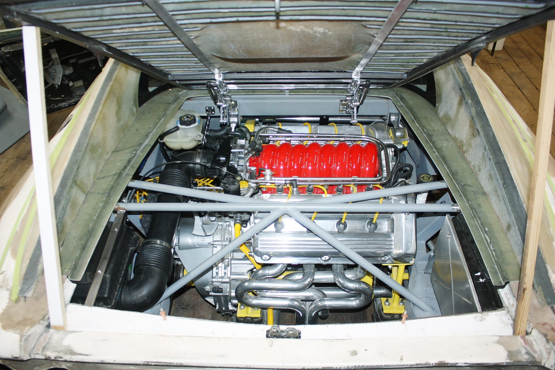
I had been hoping all along to use the 1997 DeVille surge tank I had on hand to avoid extra costs, but also because it seemed to fit exceptionally well in my engine bay. In fact if you peruse many of my earlier photos, you’ll see it mocked up looking like it was already installed… like this one:
First, why a pressurized surge tank? The simple answer is that it does two things a common reservoir doesn’t: it effectively increases the amount of coolant in the system by maintaining all of it in circulation at all times and; it also is more environmentally friendly because it doesn’t allow ethylene glycol vapour to be released into the atmosphere under normal conditions.
I had been hoping all along to use the 1997 DeVille surge tank I had on hand to avoid extra costs, but also because it seemed to fit exceptionally well in my engine bay. In fact if you peruse many of my earlier photos, you’ll see it mocked up looking like it was already installed… like this one:
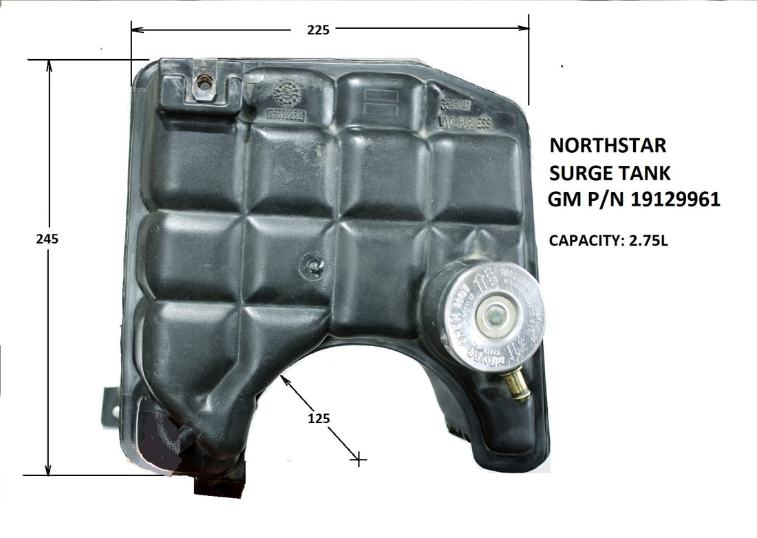
It has a large 2.75 litre capacity, a long leg that conveniently reaches down to the top of the lower frame rail making mounting it a snap, and a huge clearance area for the shifter cables to pass under it:
It has a large 2.75 litre capacity, a long leg that conveniently reaches down to the top of the lower frame rail making mounting it a snap, and a huge clearance area for the shifter cables to pass under it:
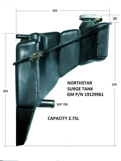
Even better, it has a semi-circular cut-out that would’ve nicely allowed the EVAP canister to nestle with it for the greatest space efficiency:
Even better, it has a semi-circular cut-out that would’ve nicely allowed the EVAP canister to nestle with it for the greatest space efficiency:
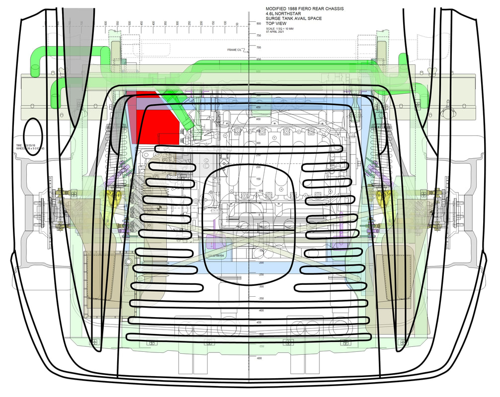
The trouble was I started out with this much room before the essential components were installed (red area):
The trouble was I started out with this much room before the essential components were installed (red area):
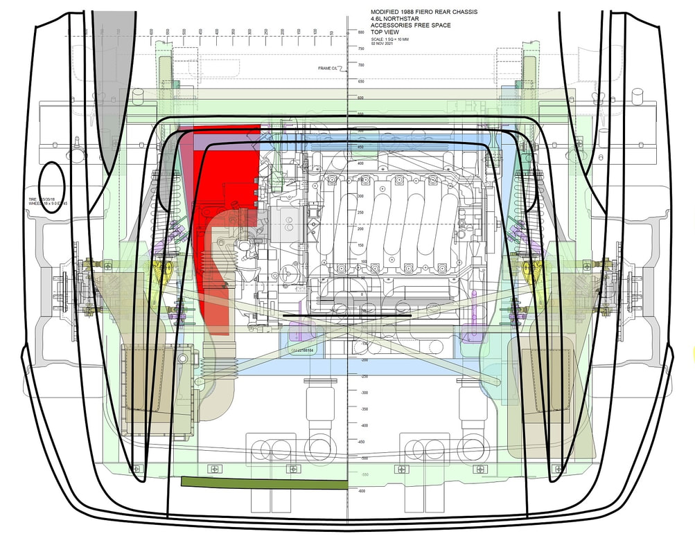
And ended up with only this much afterwards:
And ended up with only this much afterwards:
The Caddy surge tank became too big for the available space and it interfered with the shifter cables below it, despite the large cut-out under the tank. Regrettably I had to move on to Plan B.
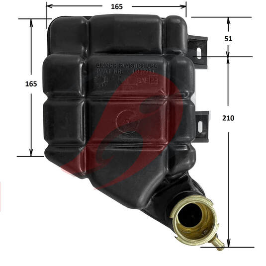
I searched the internet for alternate solutions and found the 1992-1996 Corvette surge tanks to be popular because of their low profile. They have one more large port than the Caddy tanks, but that could easily be accommodated by routing the plumbing slightly differently than on the stock Northstar:
The Caddy surge tank became too big for the available space and it interfered with the shifter cables below it, despite the large cut-out under the tank. Regrettably I had to move on to Plan B.
I searched the internet for alternate solutions and found the 1992-1996 Corvette surge tanks to be popular because of their low profile. They have one more large port than the Caddy tanks, but that could easily be accommodated by routing the plumbing slightly differently than on the stock Northstar:
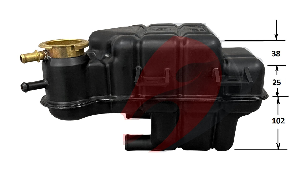
Even the configuration from the top looked promising, if not for the fact that it held 1.25 litres less than the Caddy tank. Of course dimensions were nowhere to be found on the web, and I wasn’t ready to spend $100 on a used tank only to find it wouldn’t fit. So I enlisted a long-distance friend with a C4 Corvette to measure his tank for me:
Even the configuration from the top looked promising, if not for the fact that it held 1.25 litres less than the Caddy tank. Of course dimensions were nowhere to be found on the web, and I wasn’t ready to spend $100 on a used tank only to find it wouldn’t fit. So I enlisted a long-distance friend with a C4 Corvette to measure his tank for me:
But darn it! It would only just fit between the firewall and the MAF sensor leaving no room for engine movement. So on to Plan C. Actually, it was back to the scrap yard for ideas.
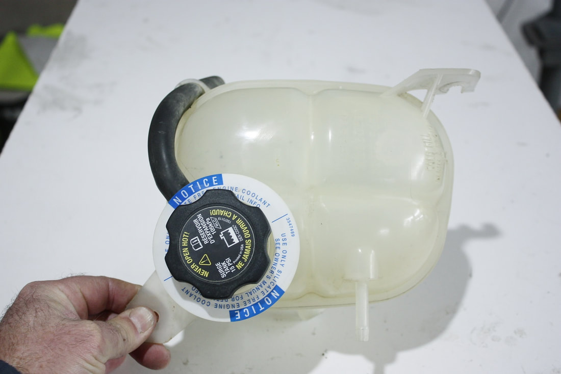
That’s when I stumbled across an ’06 Saturn Ion. The tank has a retro bulbous look rather than a modern square-ish shape but it was clean, had a large and small port like the Caddy’s, and had a GM fluid level sender.
But darn it! It would only just fit between the firewall and the MAF sensor leaving no room for engine movement. So on to Plan C. Actually, it was back to the scrap yard for ideas.
That’s when I stumbled across an ’06 Saturn Ion. The tank has a retro bulbous look rather than a modern square-ish shape but it was clean, had a large and small port like the Caddy’s, and had a GM fluid level sender.
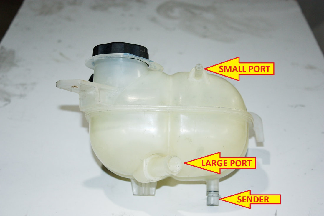
It also had two convenient mounting points, was small enough to allow engine movement, had a 1.8 litre capacity, and was only $50:
It also had two convenient mounting points, was small enough to allow engine movement, had a 1.8 litre capacity, and was only $50:
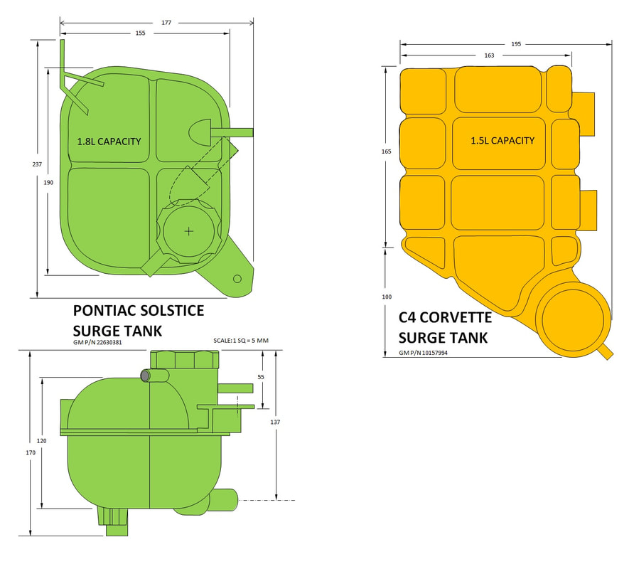
Here’s a scale comparison of the Ion/Solstice and C4 Corvette tanks… the difference in length was make-or-break for my engine bay and the extra 300 ml capacity was pure bonus:
Here’s a scale comparison of the Ion/Solstice and C4 Corvette tanks… the difference in length was make-or-break for my engine bay and the extra 300 ml capacity was pure bonus:
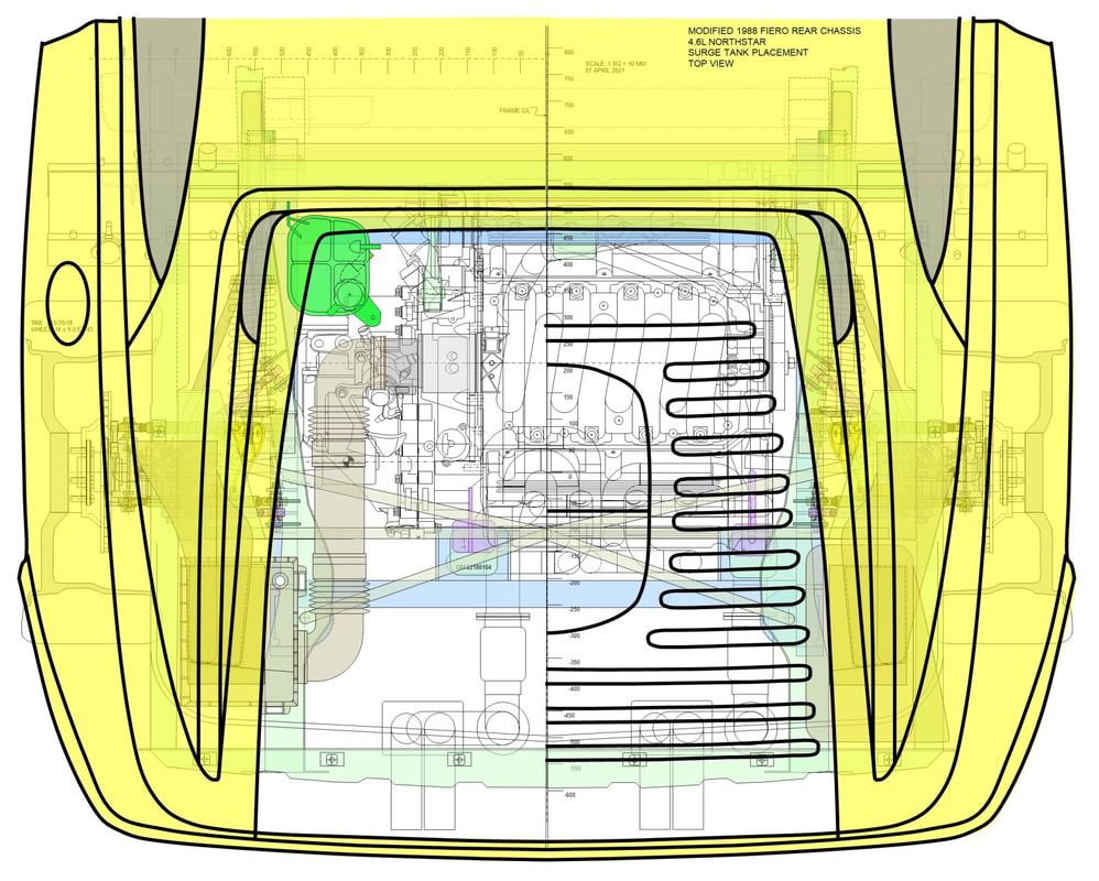
Obviously the location and orientation were equally important to the dimensions of the tank. For the tank to work properly, the pressure cap had to be mounted higher than all the other cooling system components, which would put it perilously close to the underside of the decklid.
Though it almost goes without saying, the filler cap also had to be accessible. I’ve seen too many people swap engines without any regard for basic maintainability. I didn’t want to have to remove body panels or other components to top up the coolant, so here’s where the Ion tank (in green) was going sit:
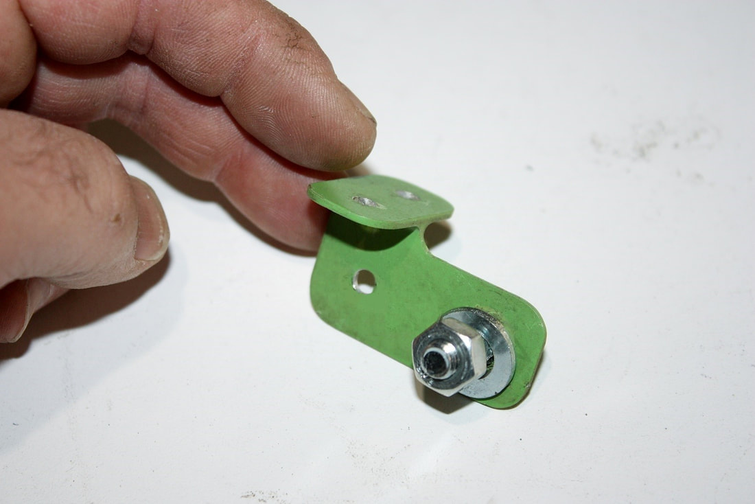
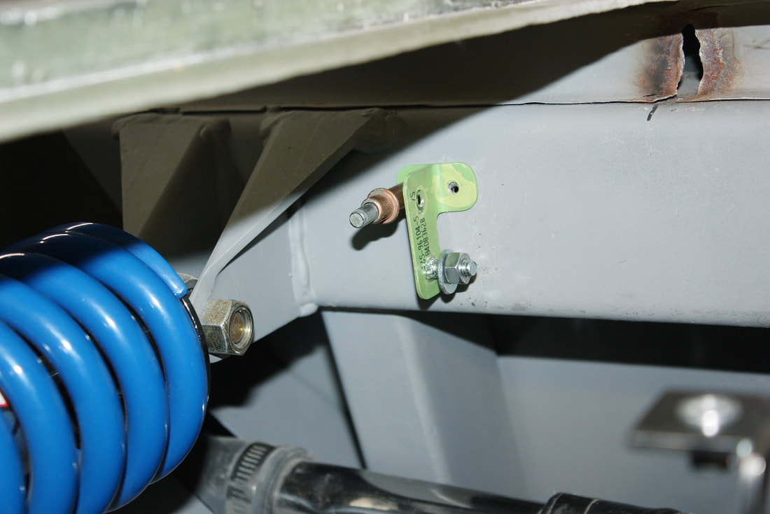
With that sorted out, the next step was to figure out some mounts. The 2”x3” steel beam I added below the rear window a while back turned out to be the perfect base for the two mounts I’d need to hang the surge tank on. From some aluminum angle, I fabricated this simple little T-bracket for one of them:
With that sorted out, the next step was to figure out some mounts. The 2”x3” steel beam I added below the rear window a while back turned out to be the perfect base for the two mounts I’d need to hang the surge tank on. From some aluminum angle, I fabricated this simple little T-bracket for one of them:
Then I measured the location carefully on the beam, drilled it, and temporarily secured it with a Cleco fastener next to the driver’s side shock absorber:
Then I measured the location carefully on the beam, drilled it, and temporarily secured it with a Cleco fastener next to the driver’s side shock absorber:
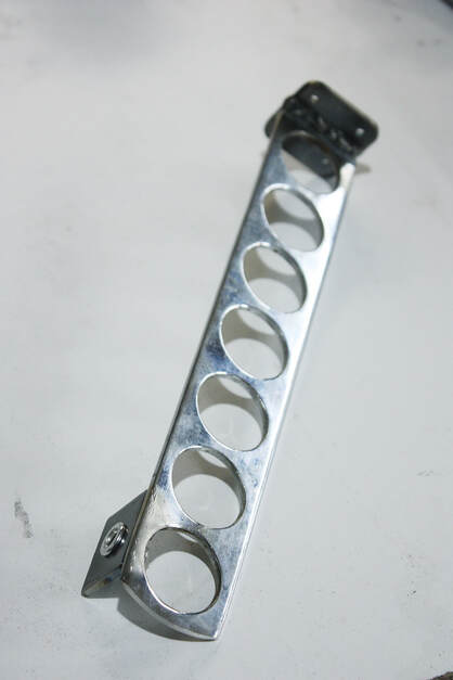
For the second mount I needed something a little more substantial since the tank would be leveraging on it over a much longer arm. I fabricated this simple bracket to attach to the front beam and to capture the mounting flange on plastic tank:
For the second mount I needed something a little more substantial since the tank would be leveraging on it over a much longer arm. I fabricated this simple bracket to attach to the front beam and to capture the mounting flange on plastic tank:
Once again I temporarily fastened the main bracket to the beam after some careful measurements. Here you can see both brackets:
Once again I temporarily fastened the main bracket to the beam after some careful measurements. Here you can see both brackets:
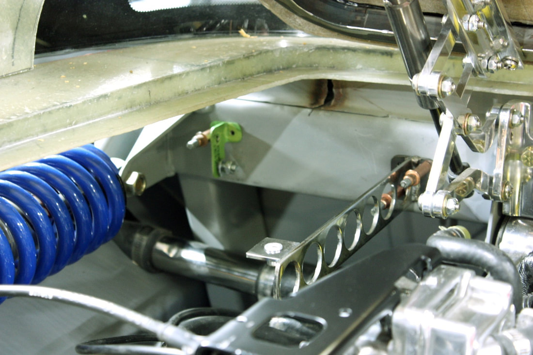
After mocking up the tank to check clearances with the underside of the decklid, the decklid hinges, and the shock/spring, I tapped the front beam to accept ¼” coarse thread bolts, and installed the brackets and tank one final time (at least for now):
After mocking up the tank to check clearances with the underside of the decklid, the decklid hinges, and the shock/spring, I tapped the front beam to accept ¼” coarse thread bolts, and installed the brackets and tank one final time (at least for now):
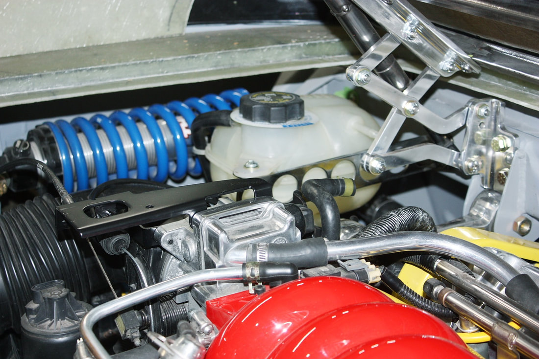
Stepping back, here’s the overall layout up to this point:
Stepping back, here’s the overall layout up to this point:
The next thing was to plumb the surge tank and in-cabin heater lines to the water log. Luckily there was still enough room under the surge tank for a couple hoses and tubes.
The next thing was to plumb the surge tank and in-cabin heater lines to the water log. Luckily there was still enough room under the surge tank for a couple hoses and tubes.
 RSS Feed
