I ended my last post with an illustration of where the two shifter cables would need to be positioned, relative to the transmission, but left them hanging in thin air. This post is about how I attached the cables to A solid mount.
The location of the cables is such that there aren’t many design options for securing the cable ends to the transmission, or anywhere else for that matter. So why not simply use the cable brackets from the Pontiac G6? The main reason is that the OEM brackets would mount on the wrong side of the levers, leading the cables away from the cabin of the car, and they would reverse the shift pattern at the in-car shift knob. That meant a custom bracket was needed.
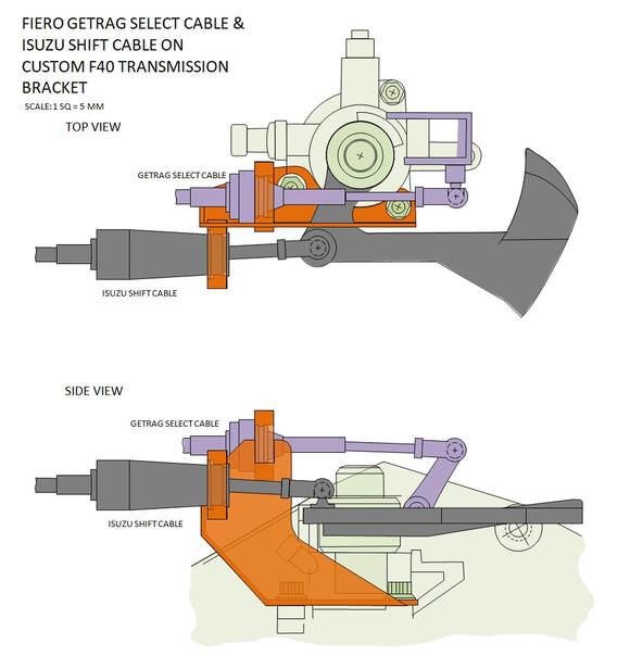
There’s very little room for a bracket, and there are only the three bolts (the ones securing the shifter quadrant to the housing) that are nearby as attachment points. So once again I turned to Fieroguru’s design for inspiration. It’s a simple, elegant, and effective bracket. His design uses two specially machined split shaft collars for securing the cable ends, which are then welded to a 1/8” steel bracket that picks up two of the three shift quadrant bolts. I copied his design (below in orange) but shortened the overall height for extra clearance in my engine bay:
I ended my last post with an illustration of where the two shifter cables would need to be positioned, relative to the transmission, but left them hanging in thin air. This post is about how I attached the cables to A solid mount.
The location of the cables is such that there aren’t many design options for securing the cable ends to the transmission, or anywhere else for that matter. So why not simply use the cable brackets from the Pontiac G6? The main reason is that the OEM brackets would mount on the wrong side of the levers, leading the cables away from the cabin of the car, and they would reverse the shift pattern at the in-car shift knob. That meant a custom bracket was needed.
There’s very little room for a bracket, and there are only the three bolts (the ones securing the shifter quadrant to the housing) that are nearby as attachment points. So once again I turned to Fieroguru’s design for inspiration. It’s a simple, elegant, and effective bracket. His design uses two specially machined split shaft collars for securing the cable ends, which are then welded to a 1/8” steel bracket that picks up two of the three shift quadrant bolts. I copied his design (below in orange) but shortened the overall height for extra clearance in my engine bay:
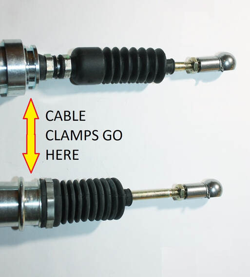
The first step in fabrication was to machine the inside diameter of a pair of split shaft collars to a shape that would capture the ends of the cables. The ends of each cable are different, so the machining operations were different as well:
The first step in fabrication was to machine the inside diameter of a pair of split shaft collars to a shape that would capture the ends of the cables. The ends of each cable are different, so the machining operations were different as well:
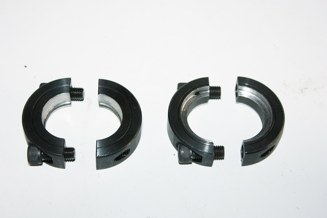
Here are the two split shaft collars after having been turned on a lathe. The exact dimensions are Fieroguru’s proprietary information:
Here are the two split shaft collars after having been turned on a lathe. The exact dimensions are Fieroguru’s proprietary information:
Next up was to make the bracket. This is the template I made using my own dimensions, but clearly inspired by Fieroguru’s design:
Next up was to make the bracket. This is the template I made using my own dimensions, but clearly inspired by Fieroguru’s design:
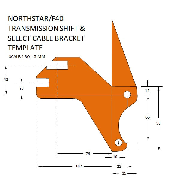
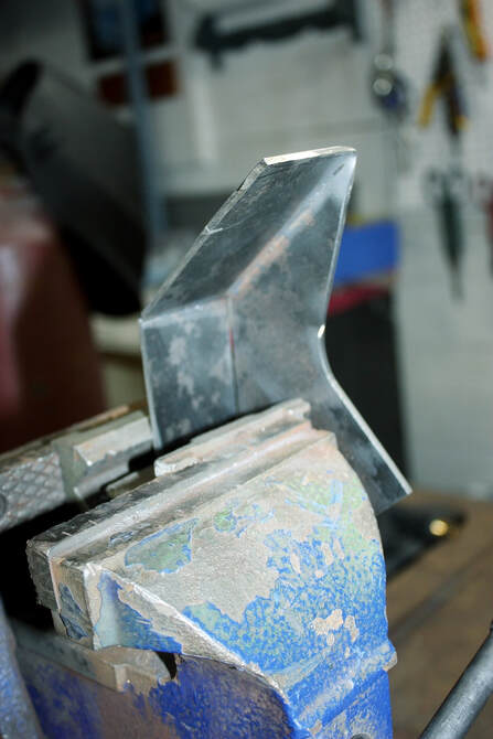
Again, I’ve only provided the minimum dimensions as a starting point for someone looking to make their own. I’ve found through experience that I can’t cut a piece of metal in the shape of the template shown, drill it, and precision bend it after the fact. Rather, I cut the metal leaving three rectangular blocks somewhat larger than the template’s three “lobes”. Then I make the folds using a vise-mounted bender, and weld any seams. The final two steps are to cut the rectangles into their final shape, and only then precision-measure the location for the holes and cut them. Here I was bending the creases using a mini vise bender:
Again, I’ve only provided the minimum dimensions as a starting point for someone looking to make their own. I’ve found through experience that I can’t cut a piece of metal in the shape of the template shown, drill it, and precision bend it after the fact. Rather, I cut the metal leaving three rectangular blocks somewhat larger than the template’s three “lobes”. Then I make the folds using a vise-mounted bender, and weld any seams. The final two steps are to cut the rectangles into their final shape, and only then precision-measure the location for the holes and cut them. Here I was bending the creases using a mini vise bender:
Once the bare bracket was shaped, welded, and drilled, I mocked it up on the transmission shifter quadrant without the shaft collars to verify a couple things: clearance under the CAI tube, proper alignment and location of the cable clamps, and clearance of the Select clamp to the coil pack. Here’s the bare bracket in place:
Once the bare bracket was shaped, welded, and drilled, I mocked it up on the transmission shifter quadrant without the shaft collars to verify a couple things: clearance under the CAI tube, proper alignment and location of the cable clamps, and clearance of the Select clamp to the coil pack. Here’s the bare bracket in place:
With the cable clamp positions finalized, I cut the slots in the bracket and welded half of each split collar to the bracket:
With the cable clamp positions finalized, I cut the slots in the bracket and welded half of each split collar to the bracket:
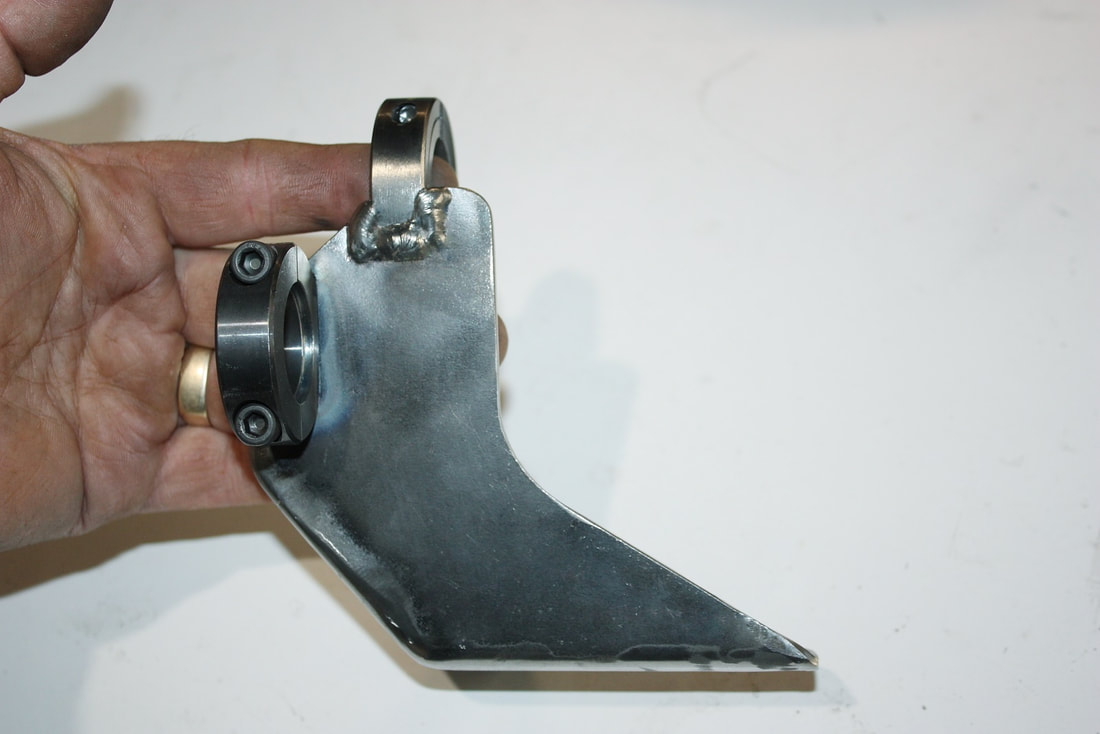
One final test fit of the bracket to the shifter quadrant…:
One final test fit of the bracket to the shifter quadrant…:
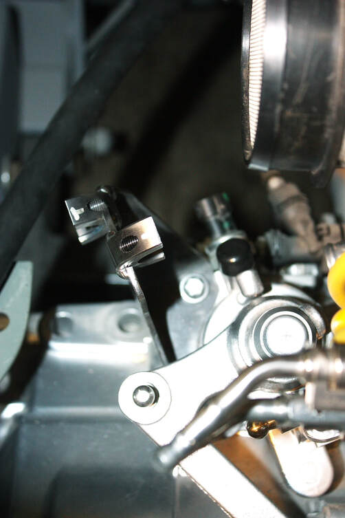
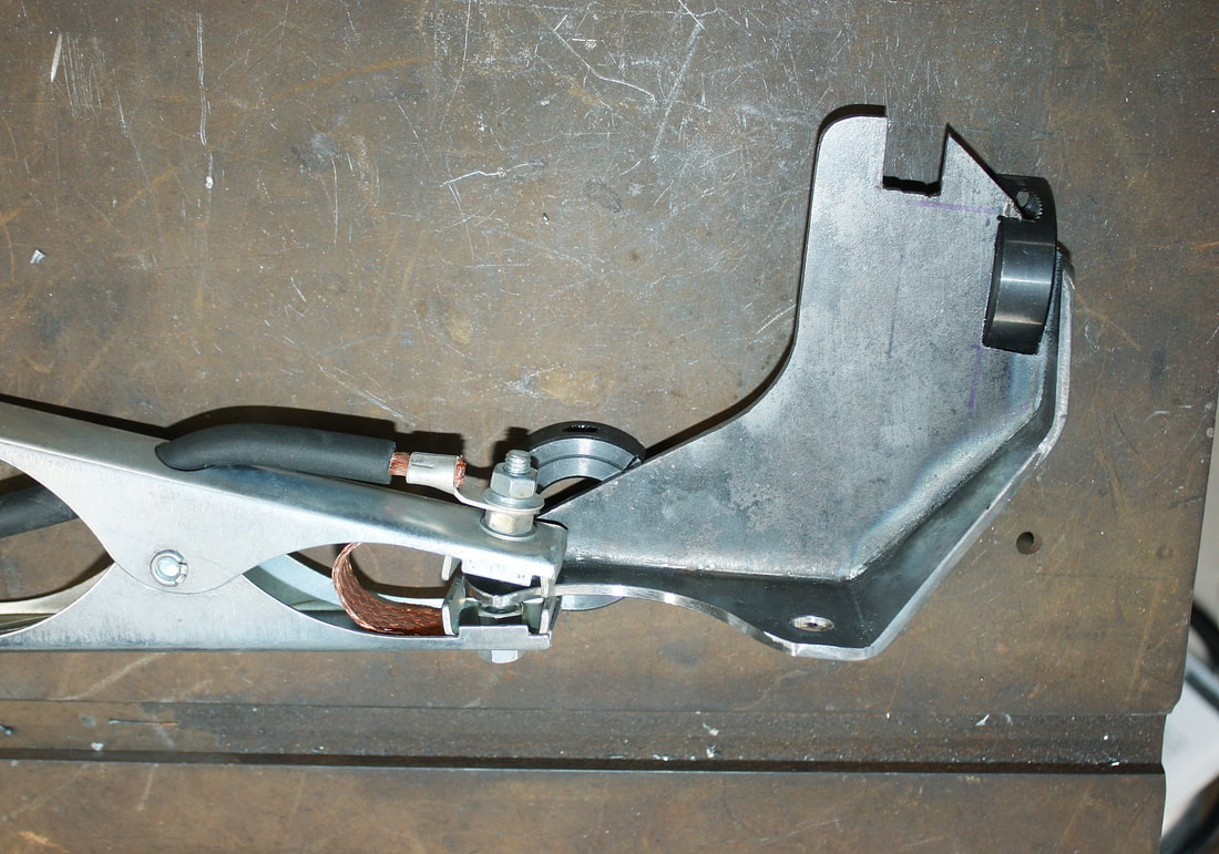
… followed by positioning and clamping the cables in place with the other half of each shaft collar, and ta-dah!
… followed by positioning and clamping the cables in place with the other half of each shaft collar, and ta-dah!
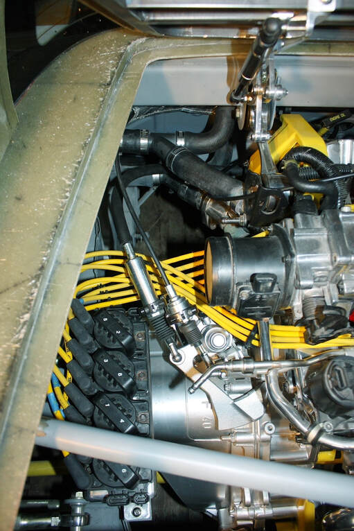
Notice the “free-space” I had earlier in this corner of the engine bay was starting to get occupied. Luckily there’s still more room!
Notice the “free-space” I had earlier in this corner of the engine bay was starting to get occupied. Luckily there’s still more room!
 RSS Feed
