I was anxious to get started on the front suspension. I jacked up the car, placed a couple jack stands under the frame and within an hour or so I had the entire front cross member out along with the stock suspension:
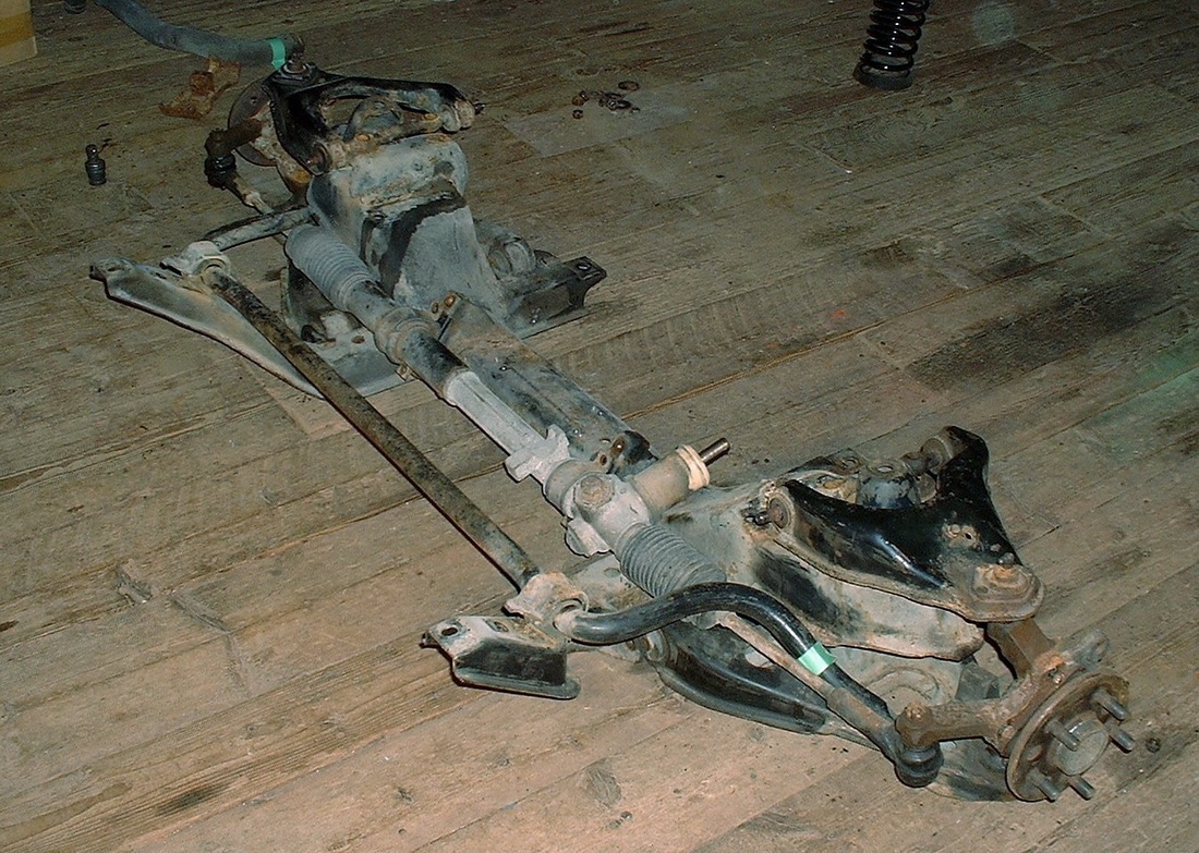
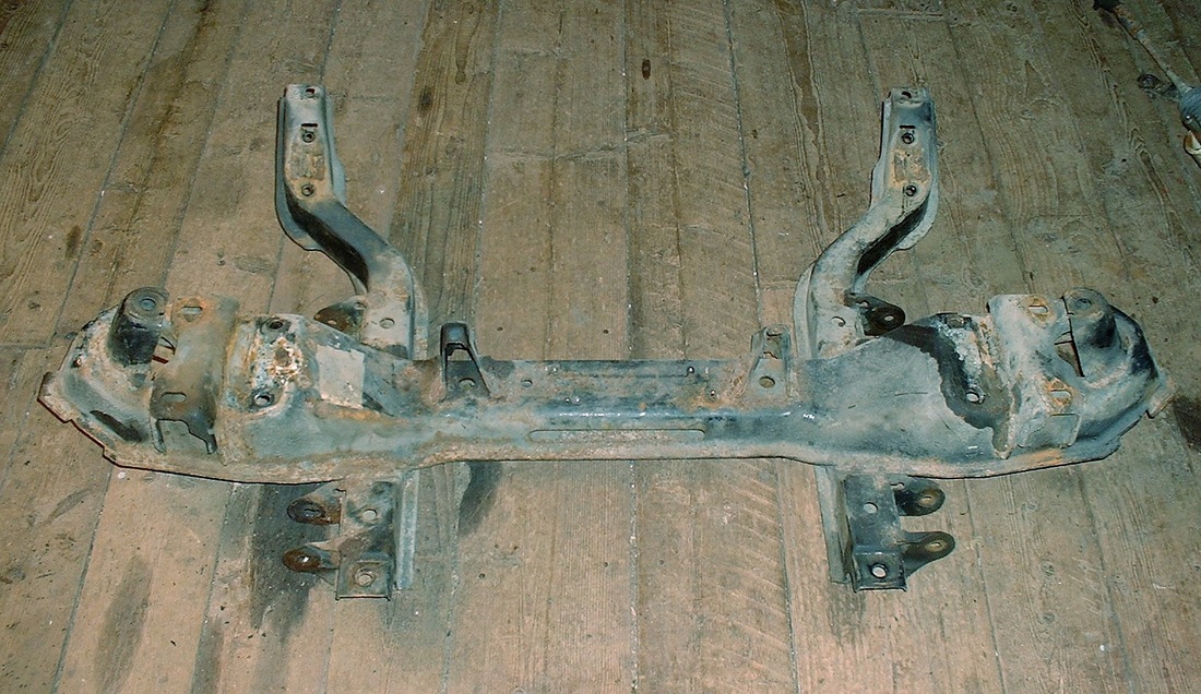
I spent another couple hours getting the suspension components off the cross member, running into the usual problems of seized bushing sleeves, and shearing bolts etc, but here is what I was ultimately after since everything else was headed for a box or two in the attic:
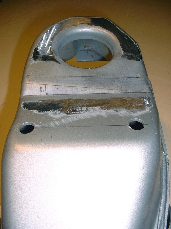
It’s amazing how a good sandblaster can take a painstaking, backbreaking, four-hour crappy task with a wire wheel on an angle grinder, and turn it into a joy to do. It took me less than half an hour and two $10 bags of crushed glass to strip the old paint and rust out of every pore, nook, and cranny of the front cross member. Once stripped, I got it primed with an epoxy primer and a couple hours later it was painted in the final colour.
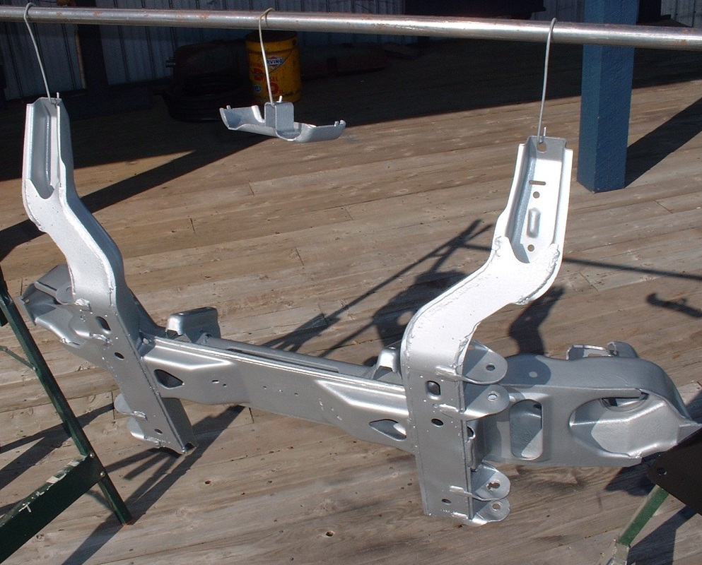
I chose silver because I wanted a different colour than the bottom of the car (which will be black), and a light colour makes it look less heavy. Few people will ever see the bottom of the car, but I want those who do to see right away that this was a ground-up restoration.
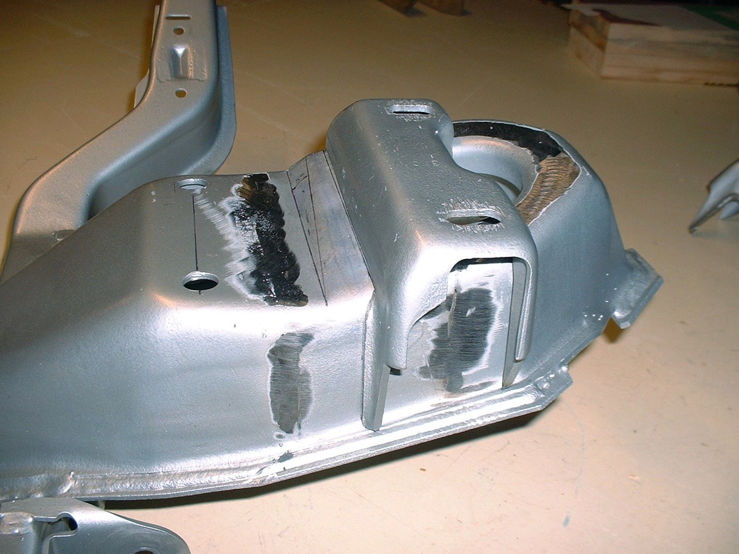
The next thing on the agenda was making the modifications to the shock tower and upper control arm mounts. I started by having a close look at stock configuration:
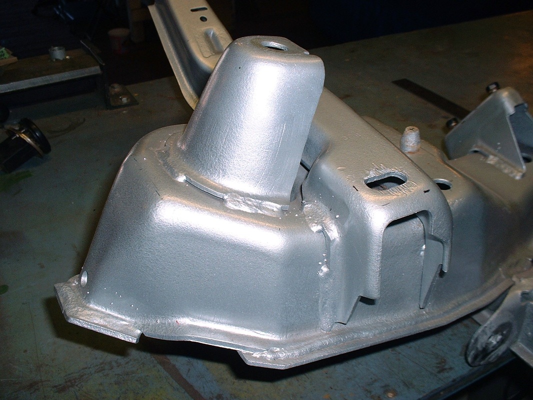
Both were only held on with stitch-welds, so I decided to go gently with a cut-off wheel in the die grinder to minimize any collateral damage to either part. I started with the shock tower since it was in the way of getting the control arm mount off anyway:
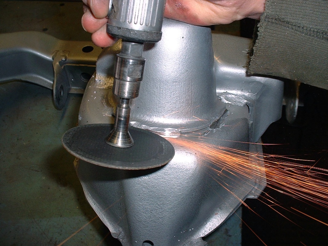
It took about 15 minutes of grinding to remove each shock tower... it surprised me how hard the metal was, but they eventually succumbed:
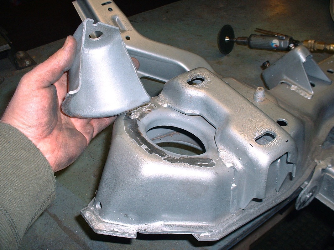
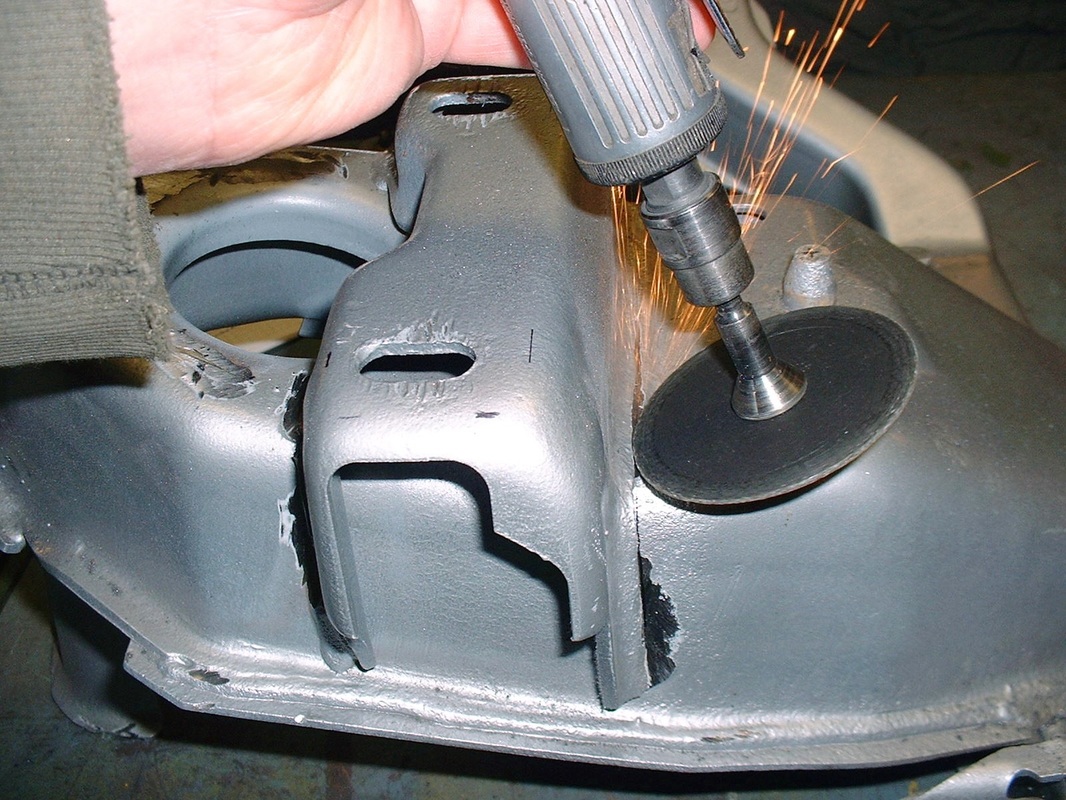
The control arm mounts were next. The odd angles and obstacles meant that the much more powerful angle grinder with cut-off wheel just wasn't going to fit. It took a solid 1/2 hour to cut off each mount:
Next, I was looking at the prospect of modifying the mounts so they would retain the 5 degree slope backwards for anti-dive, and mounting them further uphill onto a surface that was sloped 15 degrees sideways, and yet somehow remain at the same overall height. It seemed less daunting on paper.
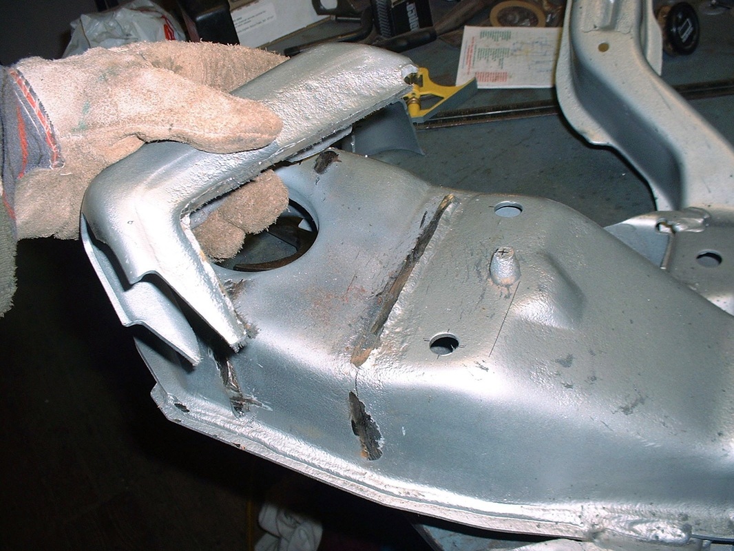
Then I realized the entire 15 degree laterally sloped upper surface of the cross member was also tilted with a built-in 5 degree slope longitudinally (backwards):
The OEM mount straddled the straight-and-level portion and the sloped-and-tilted portion of the crossmember, so it was designed to account for this strange transition. By moving the UCA mounts outboard 35 mm, they ended up entirely on the compound sloped surface. This simplified the modifications to the mounts greatly since I needed only worry about retaining the original height of the mount, while accounting for the 15 degree lateral slope. The 5 degree longitudinal slope would take care of itself.
Here is a side by side photo of the two UCA mounts with the one on the left being the newly modified one:
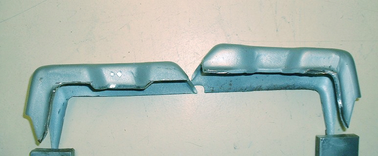
So the only two operations that were needed were to eliminate the built in 5 degree anti-dive by first making the bottom parallel with the top, and then shortening the overall height of the mount to account for it being moved up the 15 degree slope.
With the first mount trimmed just right, I test fitted it to the cross member and measured it for being level in the lateral (cross-car) plane, and for 5 degrees in the longitudinal (fore & aft) plane.
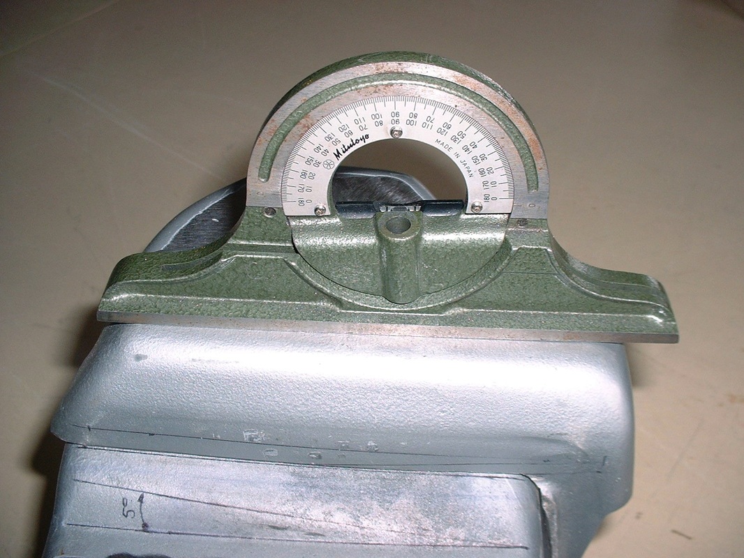
A bit of fine tuning with a file and it was ready for welding:
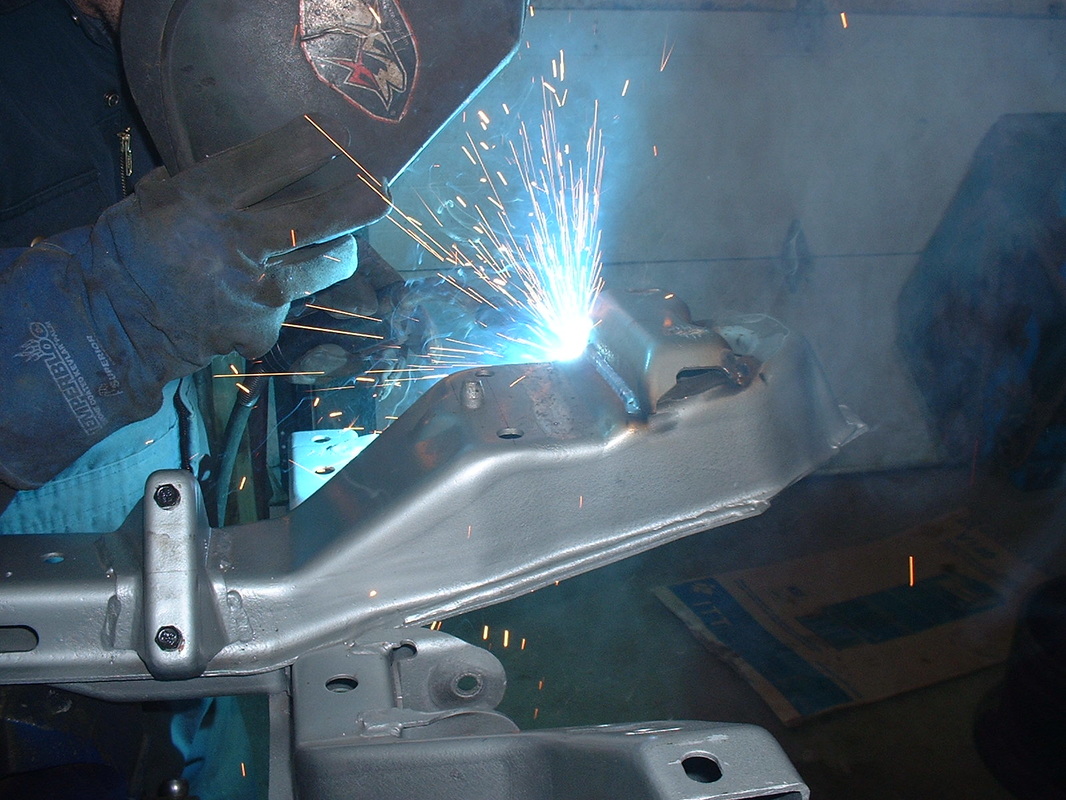
Once the welds cooled, I double checked the measurements to be sure nothing had moved.
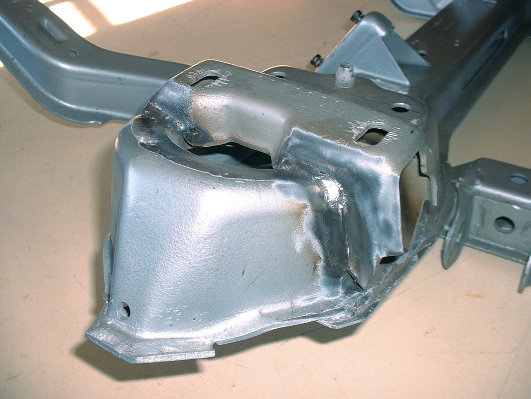
So far, so good.

 RSS Feed
