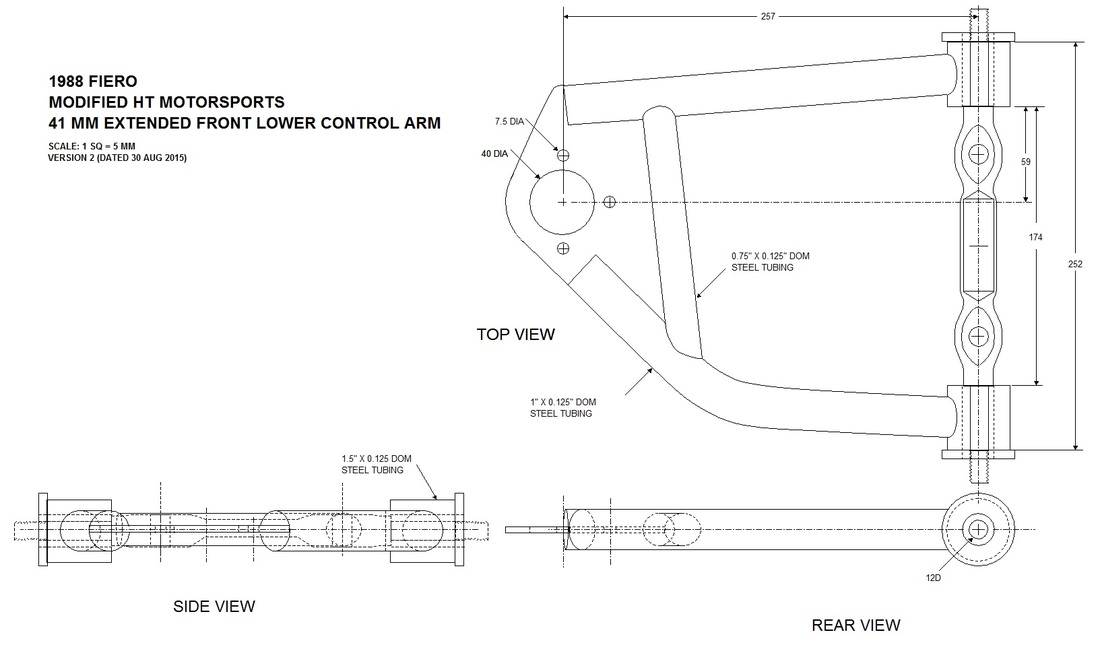
I wasn't sure whether to call this post "UCA Shortening" or "UCA Lengthening" because I'm shortening the long aftermarket arms but they're still going to be 41 mm longer than stock. Anyways, the first step was to make an accurate drawing of the final configuration for my files, and to help make the jig to weld it all back together:
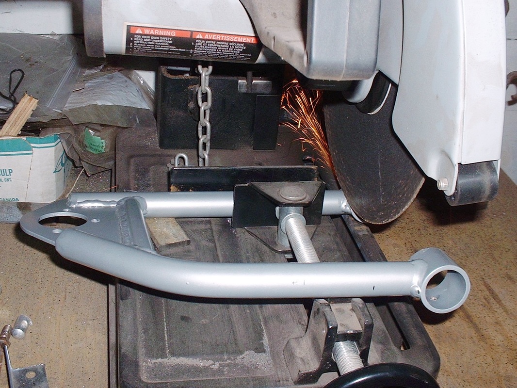
Obviously having moved the mounts on the cross member outboard 35mm meant that the aftermarket control arms would have to be shortened by the same amount. So I clamped the first arm into my chop saw to cut as close to the bushing housings as possible. I have to admit I had a moment of doubt as I started the saw... seemed crazy to be chopping up a nice new shiny part. Then I let her rip:
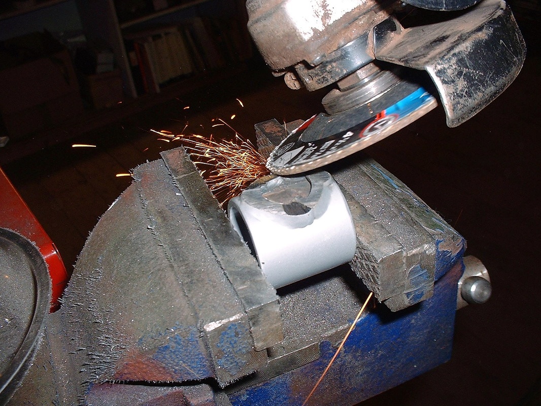
Once all four bushing housings were amputated, I chucked them up in the vise and carefully cleaned off the old welds with the angle grinder.
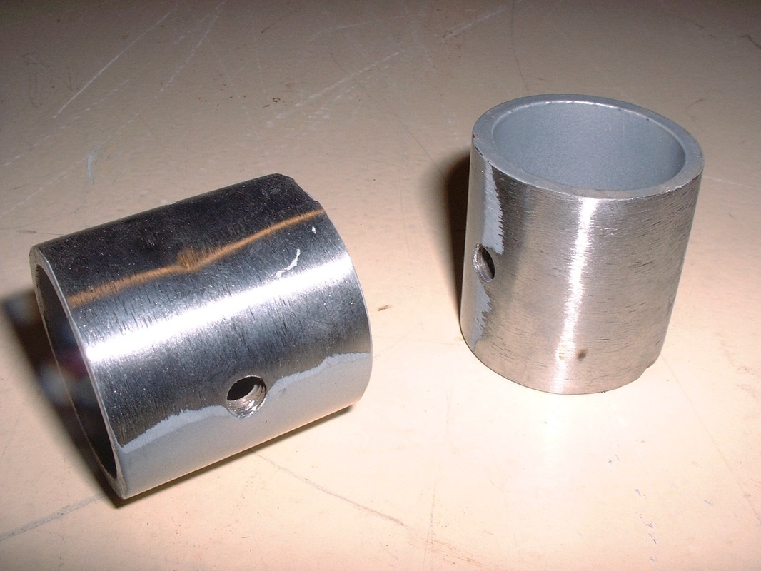
By the time I was finished the last one, the first one had cooled off enough to hold it to the belt sander for final dressing and preparation for the new welds (the tapped holes are for grease nipples):
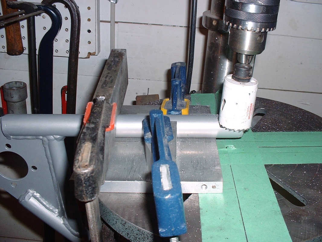
The next operation was to build a rigid jig on the drill press table to make the fish-mouth cuts in the arms at the correct location, and at the correct angle to ensure the concentricity of the two bushing housings. It wasn't as straight-forward as it could have been since the control arm legs meet up with the bushing housings at odd angles. The curved leg meets up at 3 degrees, and the straight leg at 5 degrees. My angle finder (resting on the table) paid for itself this time around:
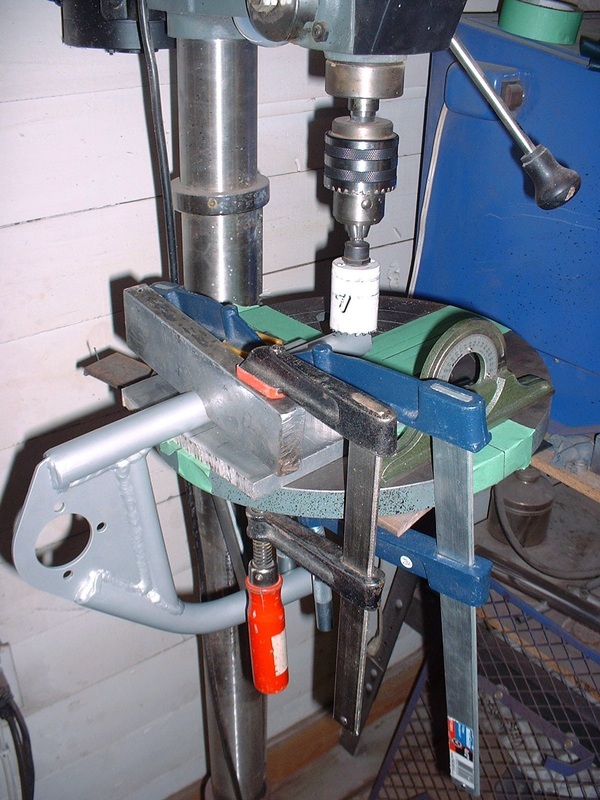
The bushing housings are 1.5" in diameter, so that's the size of the hole saw needed:
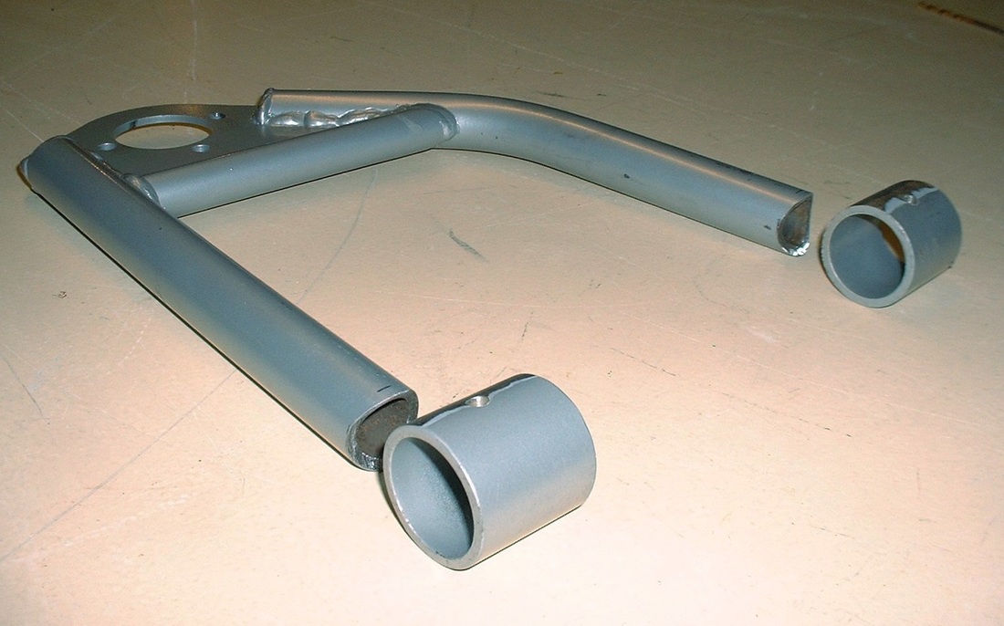
And here's one shortened (lengthened?) arm ready to be mounted in the re-welding jig:
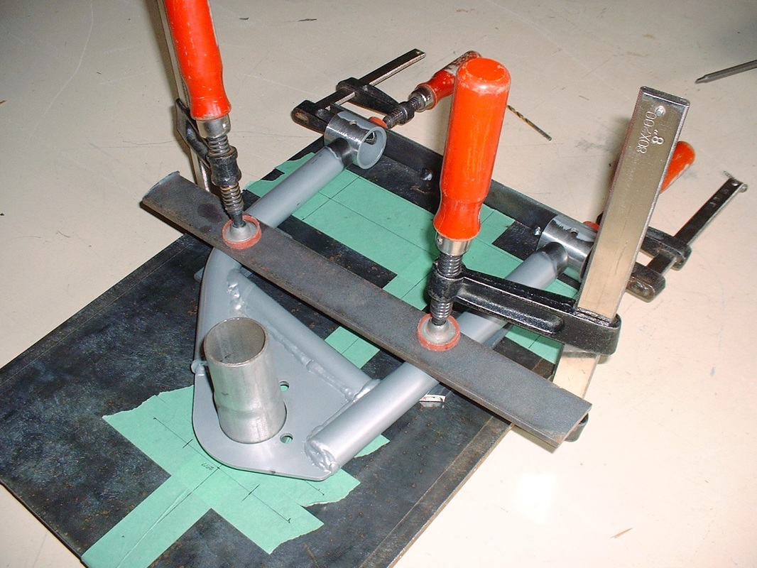
To re-weld the bushing eyelets back onto the control arms, I had to make another small jig out of some 1/4" steel plate, some angle iron, and a piece of exhaust tubing. After tacking the angle iron onto the plate as a back-stop for the bushing eyelets, I transferred the key dimensions of the shortened control arm onto the steel plate. This gave me the exact location for the ball joint in relation to the two pivots. After bringing a short piece of exhaust tubing to a local muffler shop to have them expand it to the correct diameter, I tack-welded it to the sheet metal plate to act as the ball joint alignment pin, like so:
Once the three control arm pieces were clamped in place, it was a simple matter of tack welding the parts together so they wouldn't move:
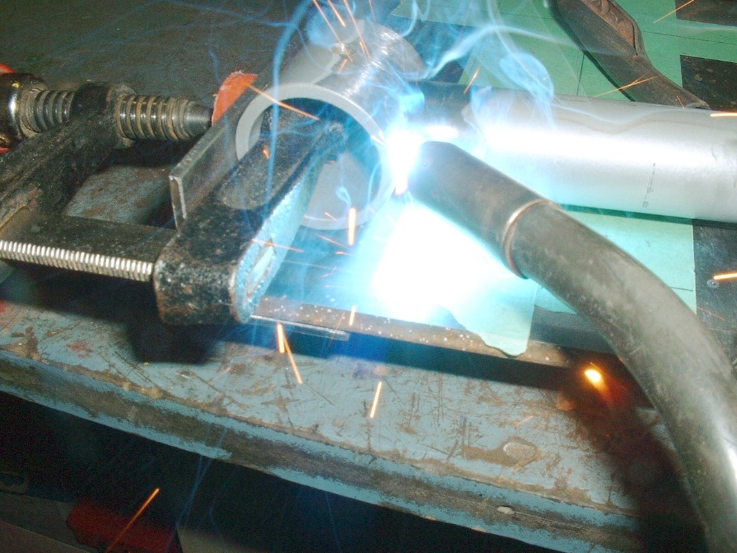
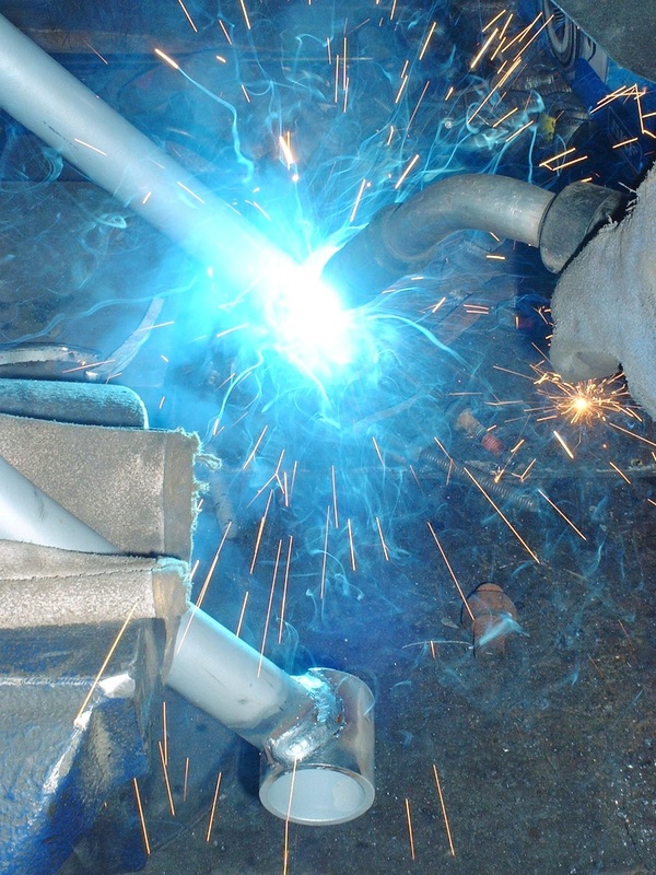
Then I removed the arms from the jig to allow me to finish-weld the joints 360 degrees around:
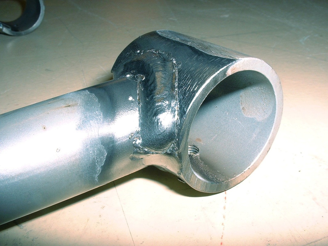
When the smoke settled, I cleaned up the burnt off paint with a wire wheel. I had to grind one small nugget from the inside diameter of one bushing housing since the weld penetrated right through. No biggie.
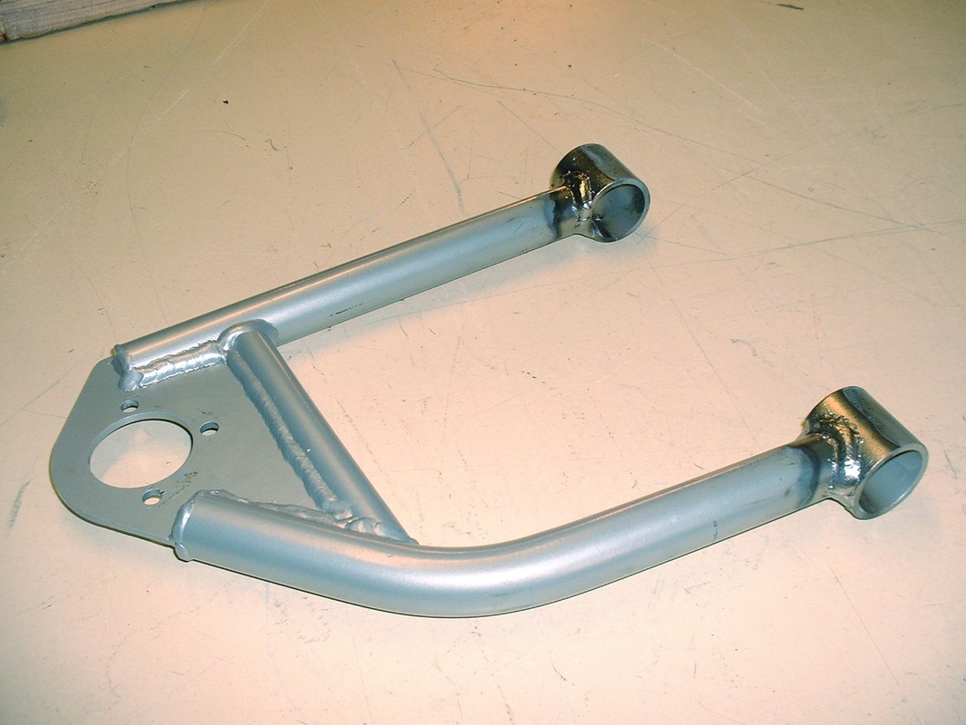
Lastly, here's an overall view of one completed arm. A little primer and some new paint and it should look like the new piece it is, only better:
I was finally ready to build up the front suspension.

 RSS Feed
