Apart from the obvious challenge of finding a small diameter clutch to hold the power of the Northstar, there were many other design issues. It would be a relatively simple task if there were a parts supplier that could or would give you the stack height of a clutch and pressure plate, or the required throw on the fingers to get full disengagement, or a whole bunch of other data needed to figure out if it'll fit and work, or not. But technical data is proprietary, leaving trial and error as the only route to success for the hobbyist. Here are just four critical criteria that any set up would need to meet:
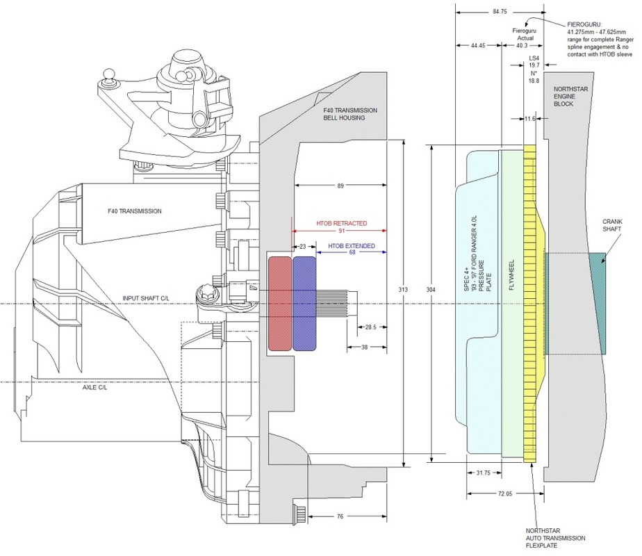
The next challenge was to design a flywheel and clutch package to mate the six speed manual transmission to the Northstar. The Northstar engine only ever came with a flex plate for an automatic transmission so a full scale design exercise was in the cards. I spent a lot of time measuring, drawing, and researching the dimensions between the transmission, engine, and various clutch assemblies and drew up some schematics. The first one shows the key relationships between one of the many configurations I considered:
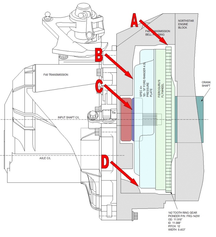
A. the ring gear had to fit inside the bell housing diameter and it had to be set at the correct depth for the starter;
B. the depth of the flywheel, clutch, and pressure plate stack couldn't exceed the depth of the bell housing;
C. the fingers on the pressure plate had sit at a depth that allowed the hydraulic throw-out bearing (HTOB) to operate within it's range; and
D. the pressure plate had to clear a differential housing bump that protrudes into the F40 transmission bell housing.
Luckily, an online friend had recently designed a flywheel to mate the same six speed transmission to an even more powerful, but different engine. He based the critical dimensions from an aluminium LT1 Fidanza flywheel, with a steel wear plate. The stars aligned when he shared his design and parts list and the only adjustment I needed to make was to the bolt pattern on the flywheel to mount it to the Northstar crankshaft, and the size of the centering hole in the middle.
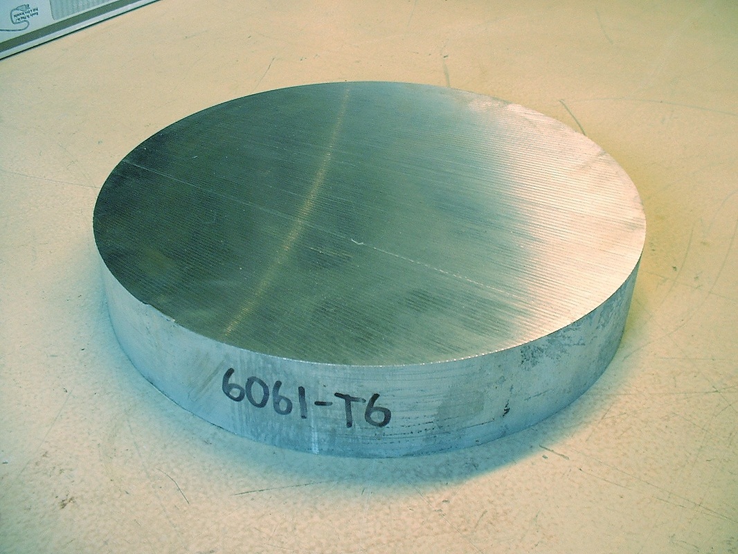
So, on to the flywheel fabrication. I bought a 2" thick, 12" diameter billet of 6061-T6 aluminium alloy for a measly $124 including shipping and taxes:
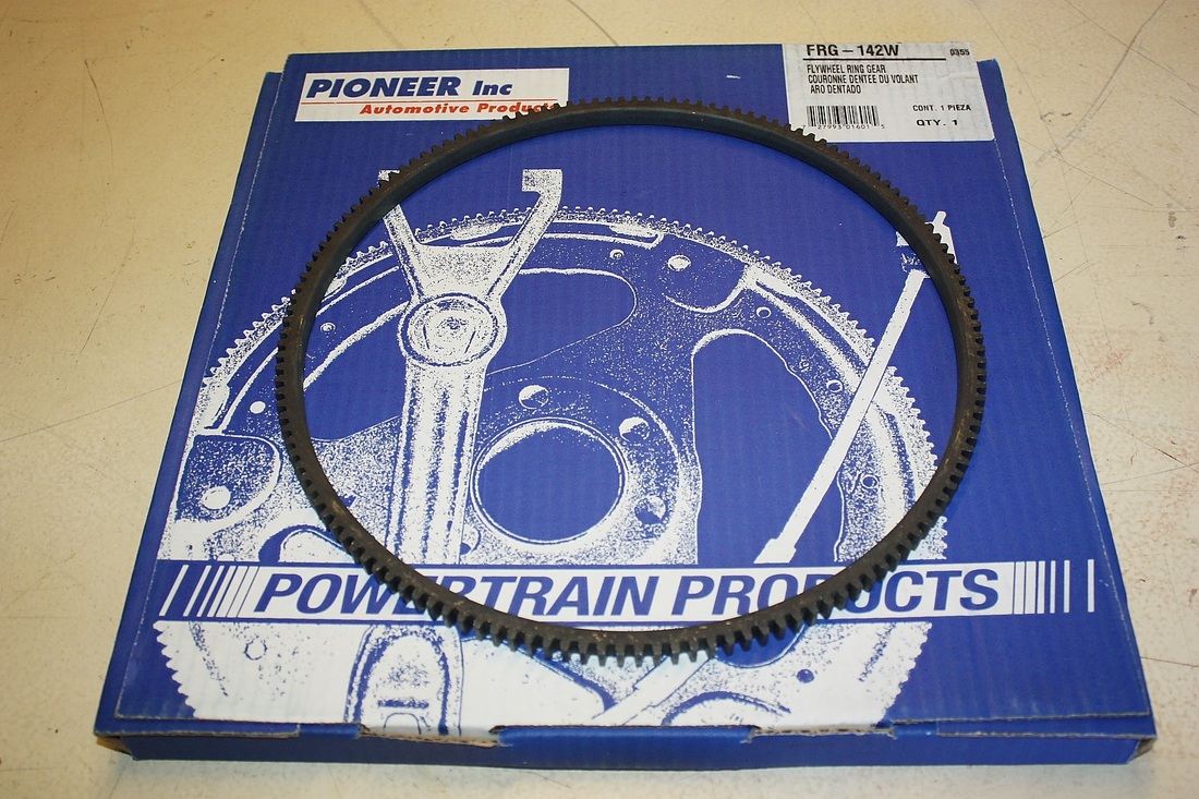
The Northstar engine uses a 142 tooth starter ring gear so I ordered a new one in advance because the machine shop needed it to gauge how large the seating surface would need to be on the flywheel for a tight interference fit. The gear cost $47 all inclusive:
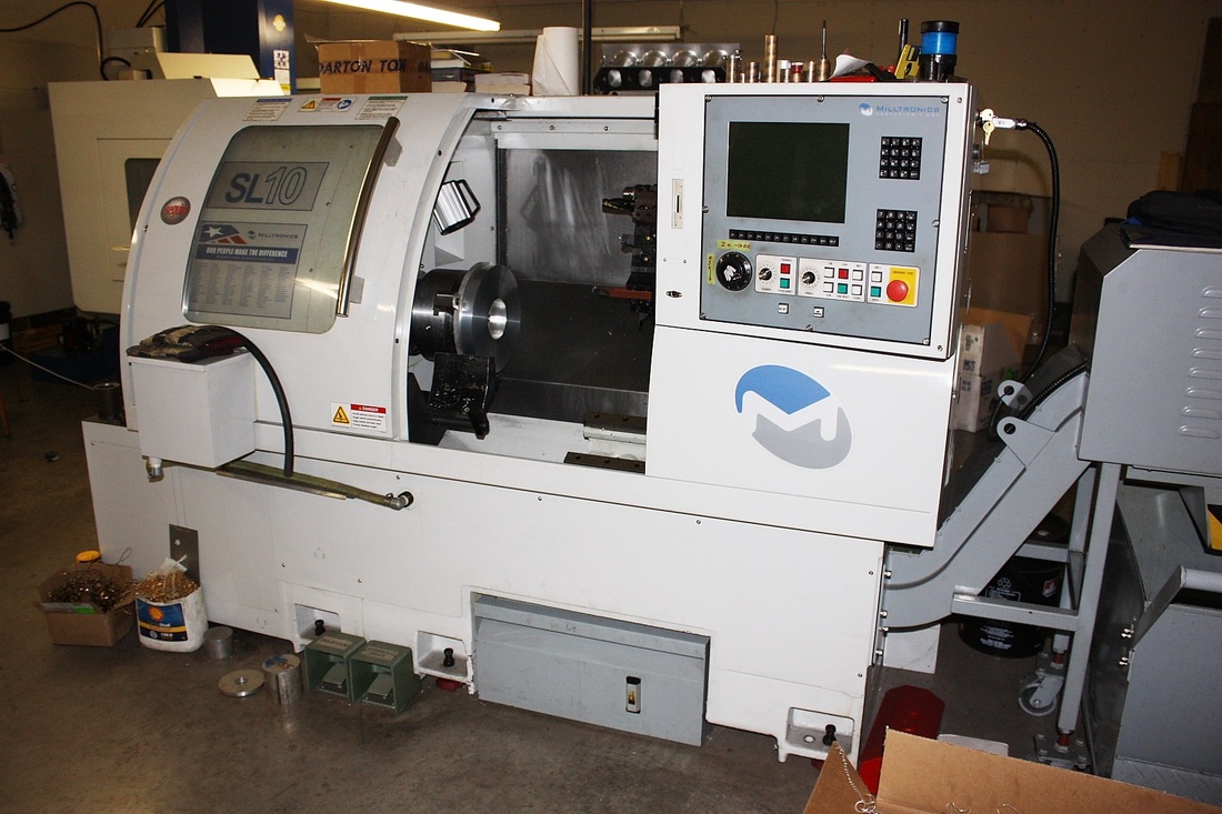
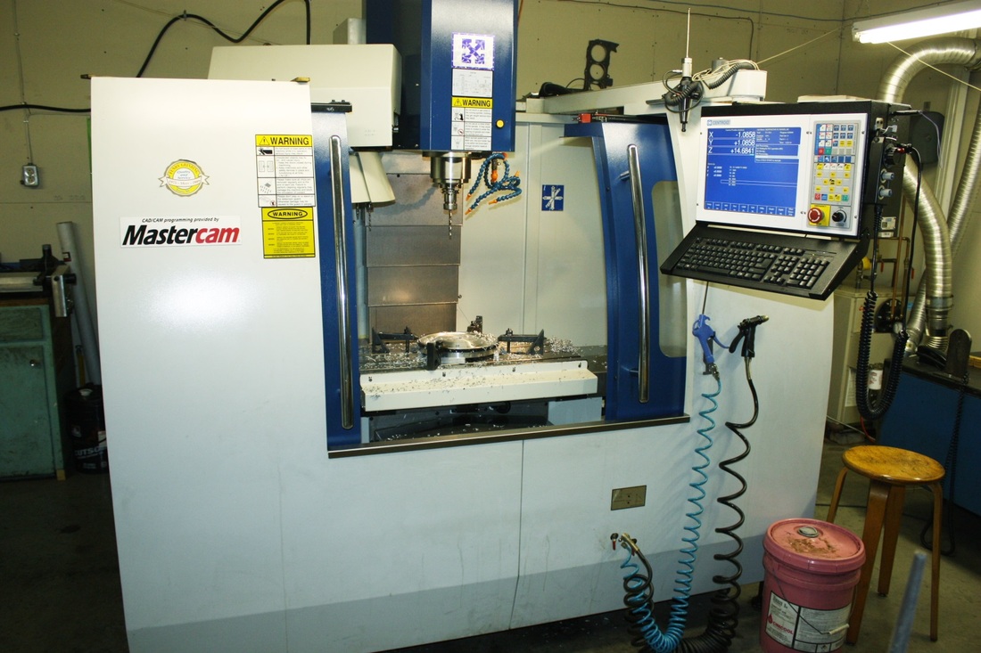
With drawings and parts in hand, I made a trip to my favorite machine shop and watched as the owner's eyes filled with delight when I gave him the instructions. He was up to his eyeballs in "mundane" engine machine work so when he got a chance to use his CNC lathe and mill for something special, he set everything else aside. Here's the lathe, and if you look closely, you'll see my aluminum disk already mounted to the chuck:
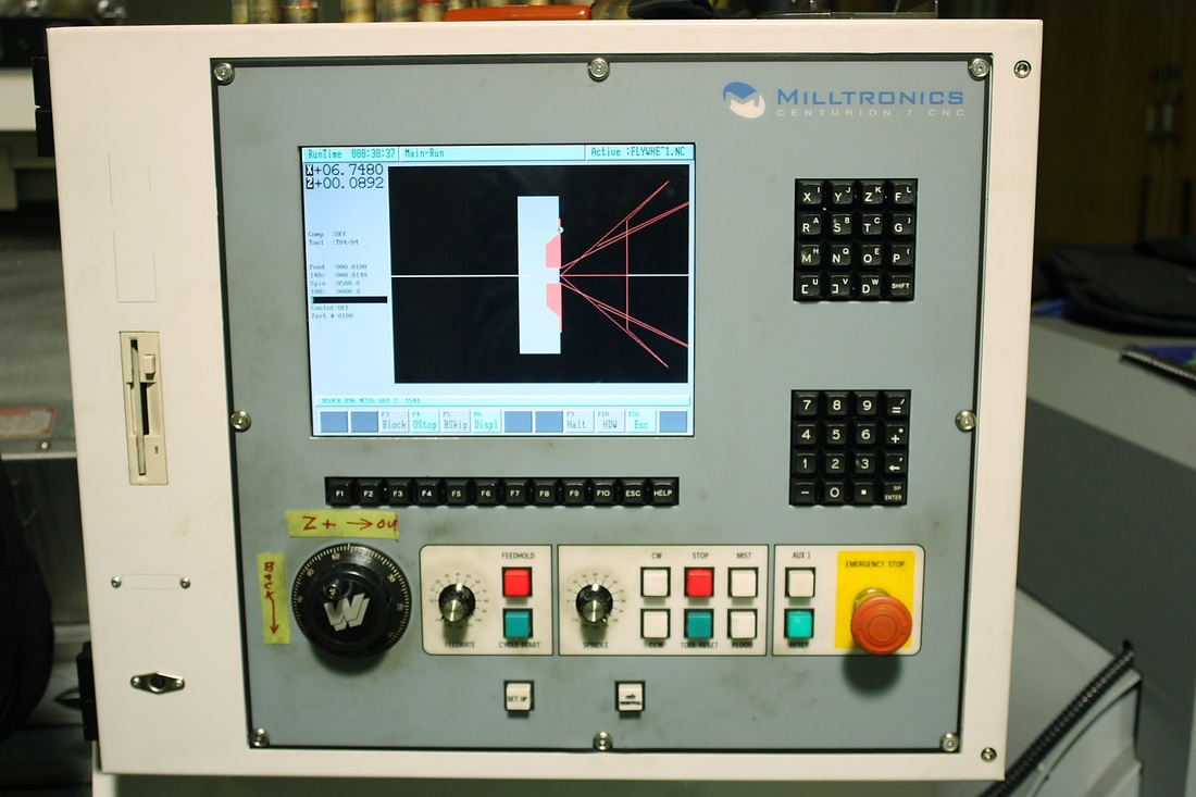
From the drawings, the machinist sat at his computer for 15 minutes and programmed the profile of the front face of the flywheel, then stuck the diskette into a port on the lathe. That's when this screen on the lathe lit up and showed the path the cutter would take:
Once that was done, all that remained was for him to close the door start the lathe and the coolant jets, and press the GO button for the cutting head to come alive:
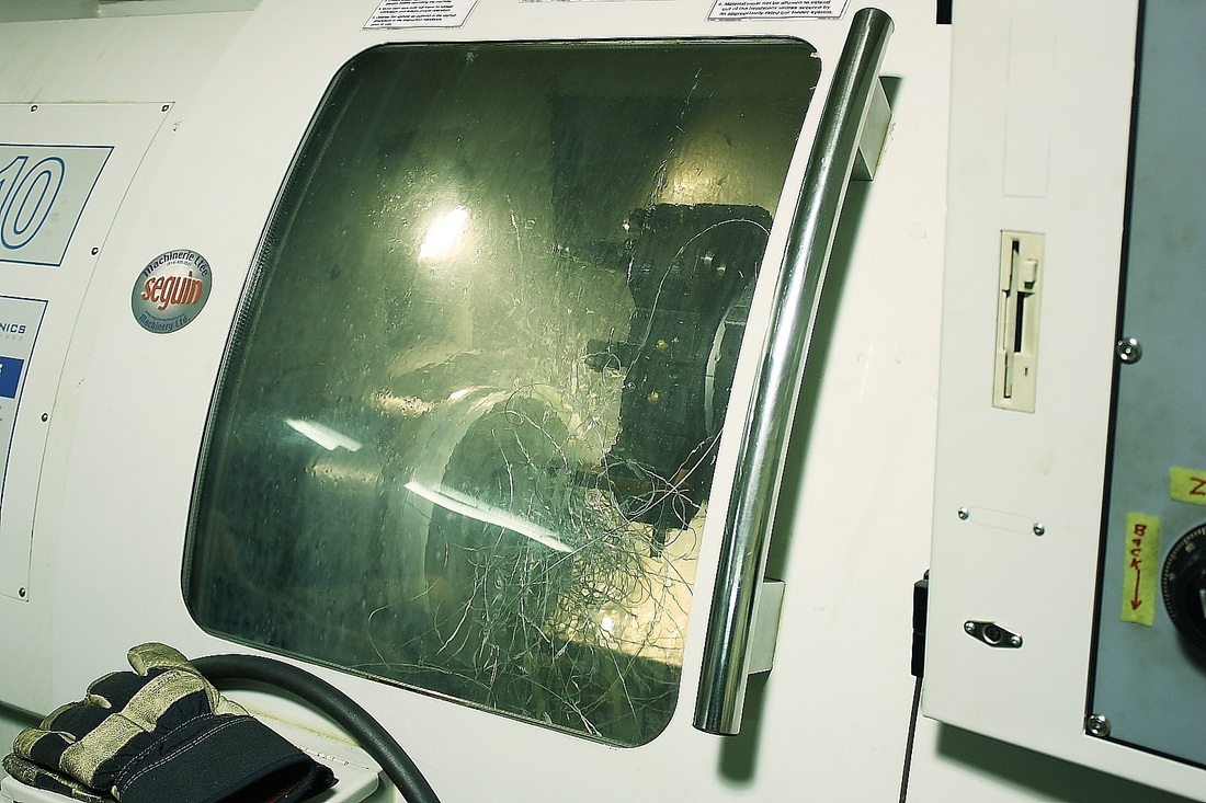
It looked more like an aluminum spaghetti factory in there after a few minutes. Every so often he'd shut the lathe down to remove the strands because they'd start to interfere with the coolant spray pattern. As it neared the end of the run, it re-traced its path to clean up any edges and without the coolant jets it made taking pictures a little easier:
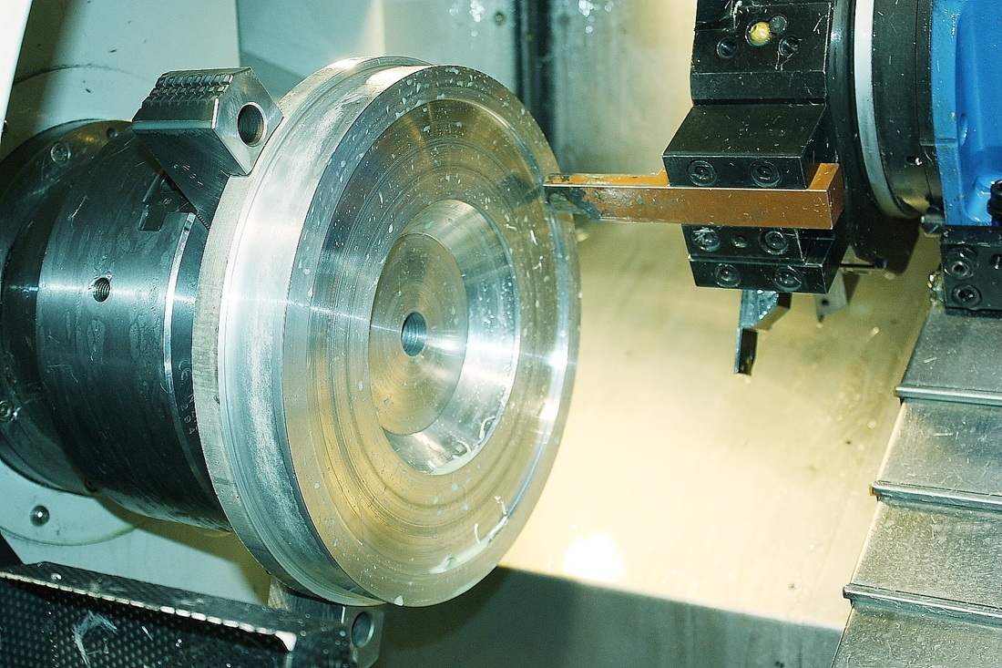
Once the transmission face of the flywheel had finished being turned, it got flipped around, the contour of the engine side was programmed, and the machinist let 'er rip again. Once both sides were shaped, the flywheel got transferred to the CNC milling machine for the holes.
Unlike in the lathe, the piece is clamped solidly to the bed and only the machine head does all the moving. 57 holes had to be drilled in perfect relation to each other for proper fit. Here's a photo of the counter-bores being drilled for the wear plate fasteners:
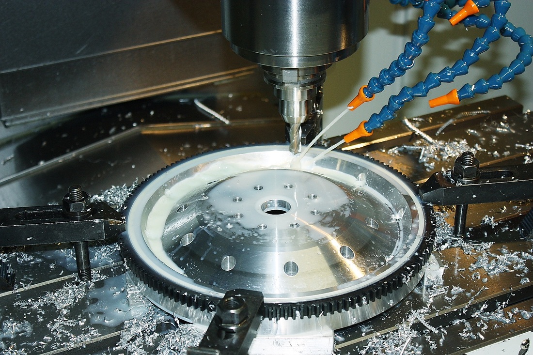
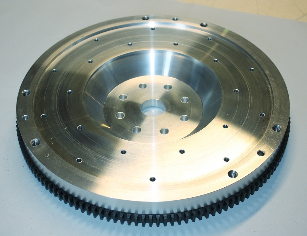
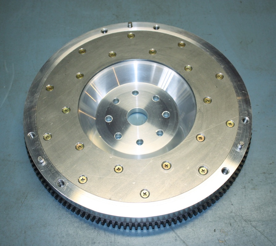
By this point the ring gear had been installed and all the holes were milled. The ring gear was heated up in an oven and slipped onto the flywheel while it was still hot. It cools down rapidly, contracting and cinching itself with an interference fit. Here's the flip side of the completed bare flywheel. Notice the countersunk groove for the steel wear plate:
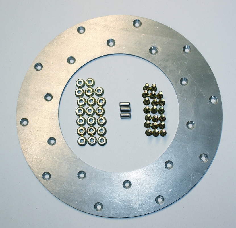
The wear plate is a steel insert made by Fidanza for '91 - '96 Dodge Stealths. It has a 10.25" OD, a 6" ID, and comes with 20 self locking nuts and machine bolts with countersunk heads. As usual, we Canadians pay about twice what Americans pay for the same part... it was $78 delivered through Amazon. All in all not terribly expensive:
The wear plate got bolted onto the flywheel using 60 in-lbs of torque. I discovered I hadn't correctly sized the countersunk holes on the backside of the flywheel to the diameter of the socket wrench I needed. The simple solution was to turn down my socket to fit. Here's the flywheel with the wear plate installed:
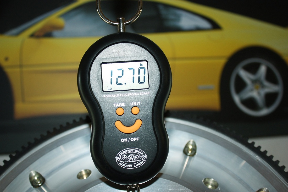
I started out with an aluminum billet weighing exactly 22 lbs. After all was said and done, the completed flywheel including the ring gear, wear plate, and fasteners, tipped the scales at 12.70 lbs. That's a lot of aluminum left on the machine shop floor! By comparison, the stock Fiero steel flywheel weighs in at 15 lbs, and the bare LS1 Corvette flywheel comes in at a whopping 24 lbs!
Total cost for the flywheel at this stage: $124 for the aluminum, $300 for machining, $78 for a wear plate, and $47 for a ring gear = $550. Not bad for a one-off, custom designed, precision machined, high-tech thing of beauty.

 RSS Feed
