With the cylinder heads installed, I moved on to the valve timing components. It was a lot more intimidating and time consuming to read through the process than it was to actually do it. Once all the parts were cleaned up and inspected, I opted to keep all of the original timing components except the primary chain tensioner. If you've been following from the beginning, you'll remember why.
There is one primary and two secondary timing sets. These are the components that form the primary timing chain assembly from top left to bottom right: crank sprocket, intermediate sprocket set journal assembly, intermediate sprocket set, chain, new tensioner, and guide.
There is one primary and two secondary timing sets. These are the components that form the primary timing chain assembly from top left to bottom right: crank sprocket, intermediate sprocket set journal assembly, intermediate sprocket set, chain, new tensioner, and guide.
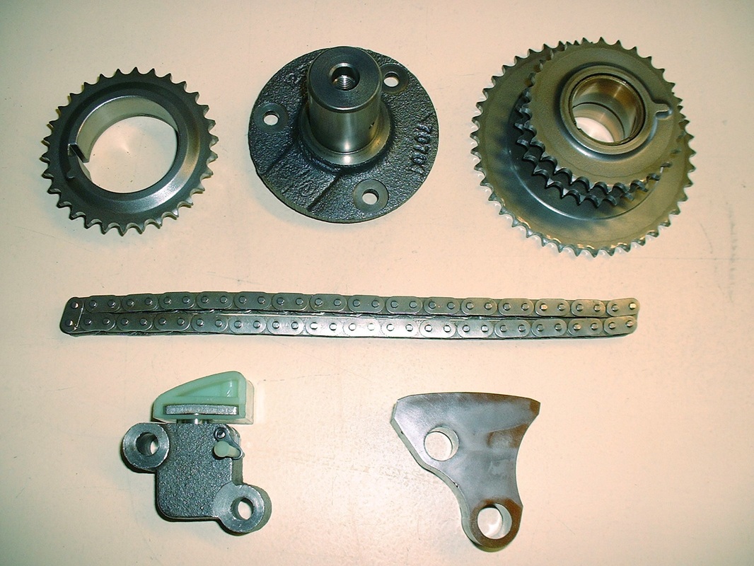
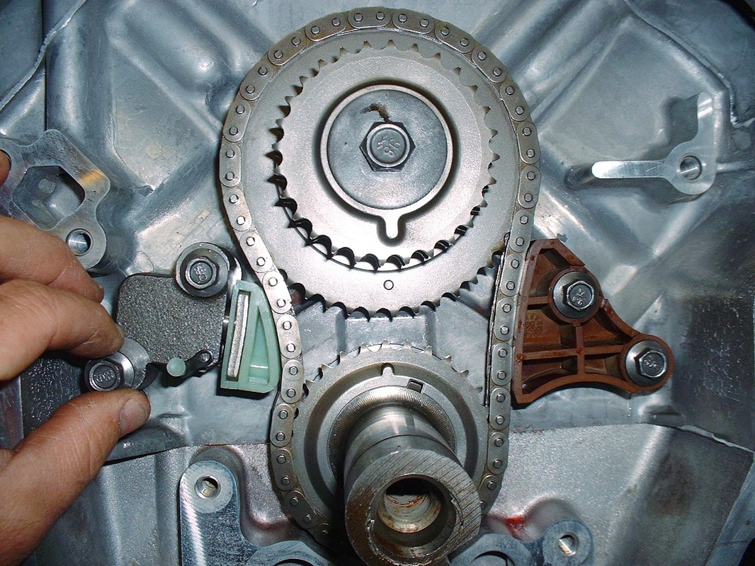
Once they're installed onto the crank, they look like this:
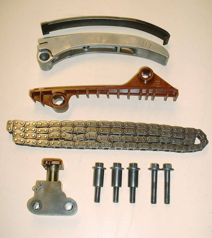
These are the main components of one of the two secondary timing chain systems, from top to bottom: replaceable upper chain guide shoe; upper chain guide; lower chain guide; chain; and tensioner:
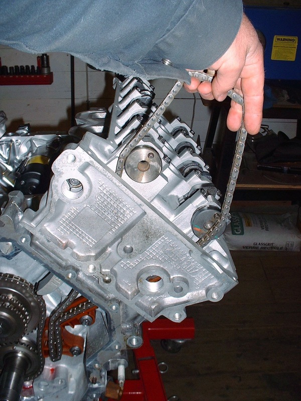
Building up the secondary timing chains was a tedious task requiring some patience, and a keen eye for details. Once the chain guides were installed, the chain was slipped through the opening in the top of the head:
Then the sprockets are installed on the camshafts in a very particular orientation and held there while the chain is wrapped around them. Because the cams are under a fair bit of tension from the valve springs, they don't rotate very easily but luckily GM had the forethought to cast a hex onto the cams so you can turn them with a wrench:
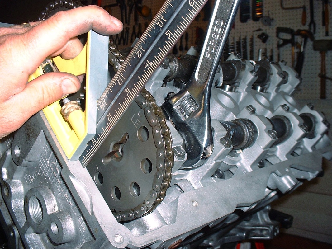
The chain gets installed in such a fashion that there's no slack on two of the three legs of the triangular configuration. The length of chain that is left slack must fall on the leg where the spring loaded tensioner can do its job. Here are the parts installed on the left (or in my case, front) cylinder bank:
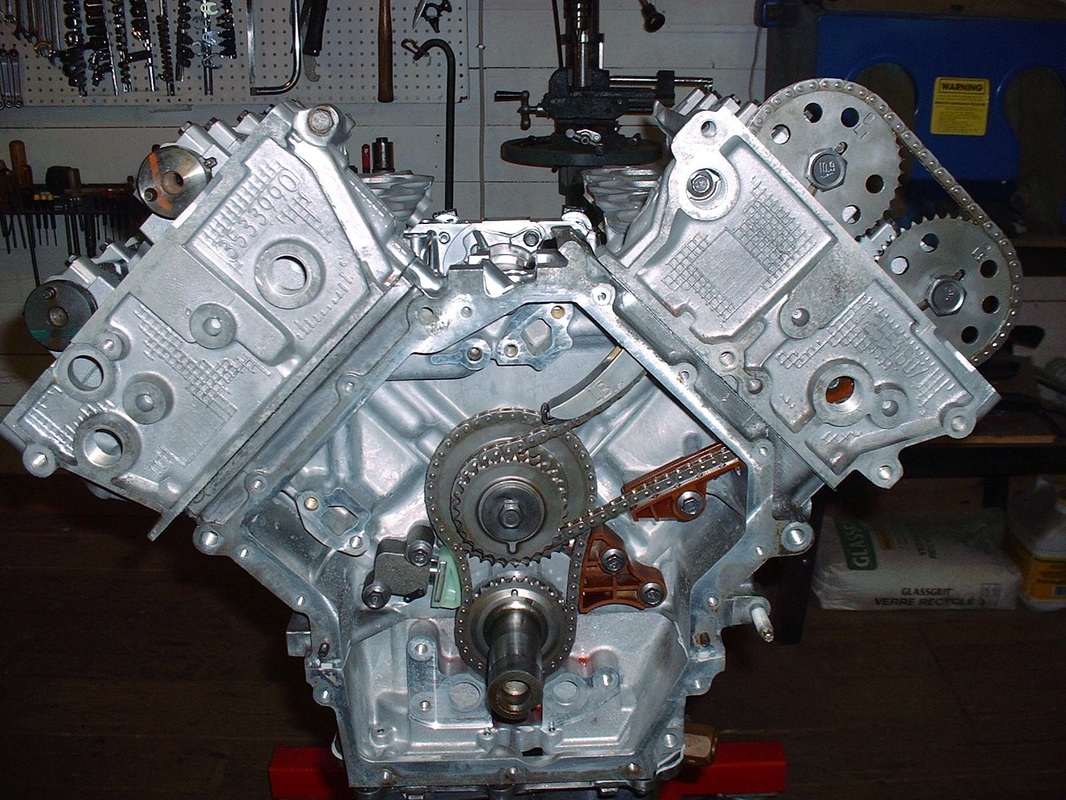
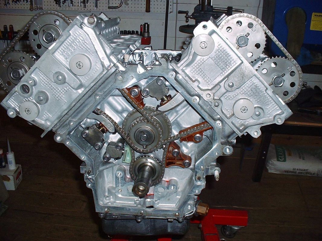
On the right (rear) cylinder bank, the process is quite similar, though one of the sprockets has a pin on it that none of the others do. The pin is part of the camshaft position sensor circuit. The sensor gets installed on the side of the head where the exhaust cam is, so it was pretty obvious which sprocket had to go where. Here is a photo of all three chain sets, guides, and sprockets installed:
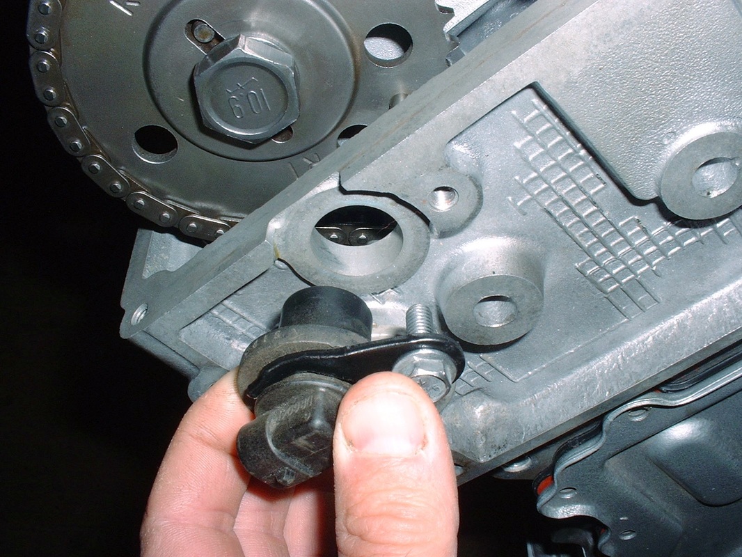
And here is the aforementioned cam position sensor being installed:
The last thing before the chain cover plate could be buttoned up was to install the oil pump. I bought a new one as cheap insurance, even though the old one looked OK. They're a pretty robust pump:
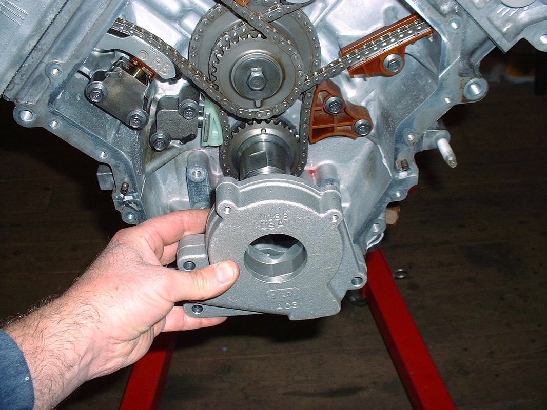
To hold the pump in place there are three screws that must be tightened in a particular sequence and then turned an extra 35*... that angle meter sure paid for itself in this engine build up!
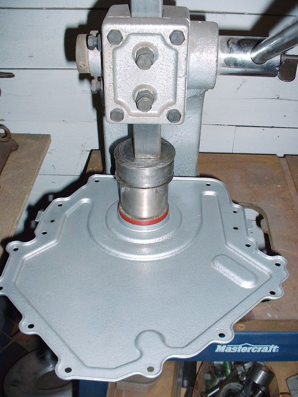
Before the chain cover went on, I replaced the front crank seal in the cover. Getting the old one out was a cinch… I just used my arbor press and pressed it from the front side, out through the back side. The new one got pressed in from the front side like so:
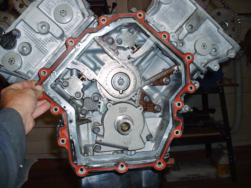
Then, a new gasket was set in place. It’s got two holes that line up with corresponding alignment pins so there’s no need to try to hold it in place. It's made of a hard composite material with an orange neoprene-like seal impregnated on both sides:
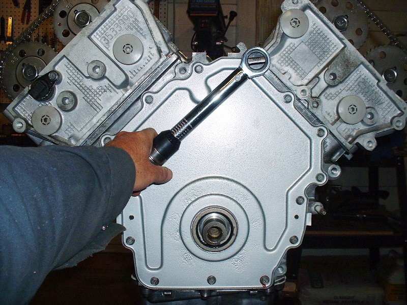
Finally I installed the cover… forever sealing up the beautiful mechanical artwork underneath:

 RSS Feed
