With all my engine block modifications done, I ran the block out to the machine shop for cylinder honing and to have it checked out generally for squareness and trueness. The machinist measured the cylinders and found they were somewhat oval, and that to bring them back into round he’d need to over-bore by 0.25 mm (or 0.010”). In this case though, it wasn’t really bored out, but rather just subjected to an extensive hone job.
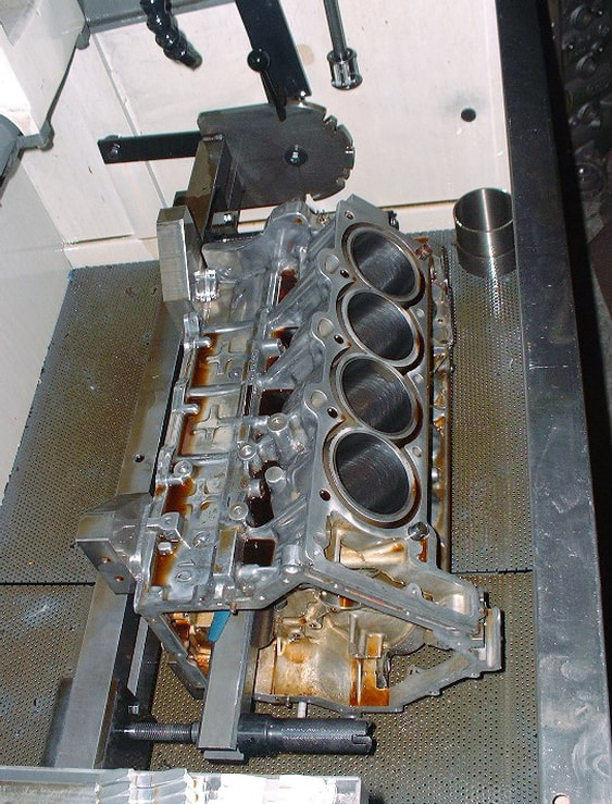
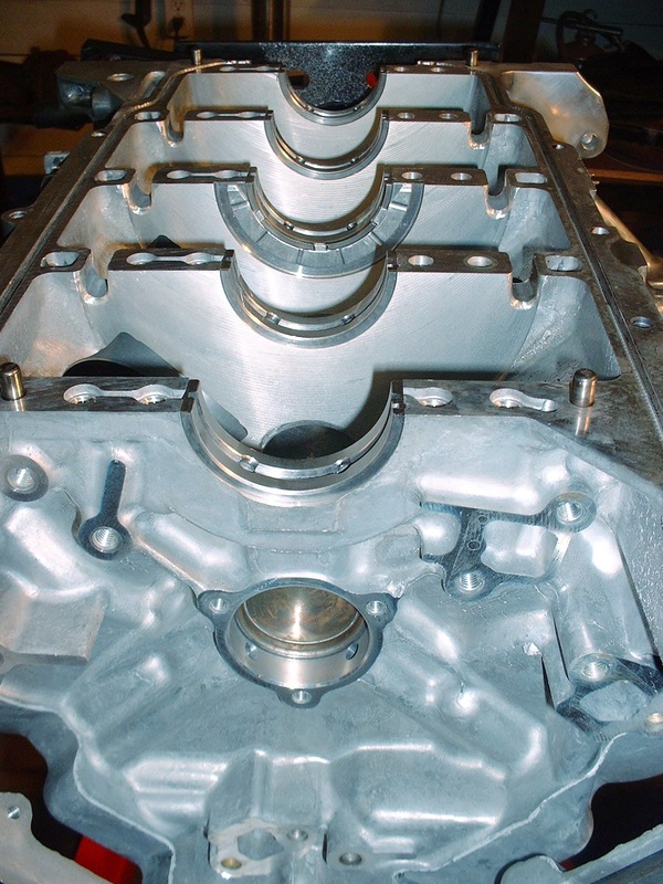
I had told him of the especially hard cylinder liners in these particular engines and that the typical silicon carbide honing stones weren't going to cut the biscuit. So he dug out the special 280 grit diamond hones for my engine. His machine is fully automated too, continuously measuring, honing, and truing at the same time by cyclically varying the stone pressures, while the operator just stands by and watches. Here’s the block sitting in the bed of the honing machine after doing one bank.
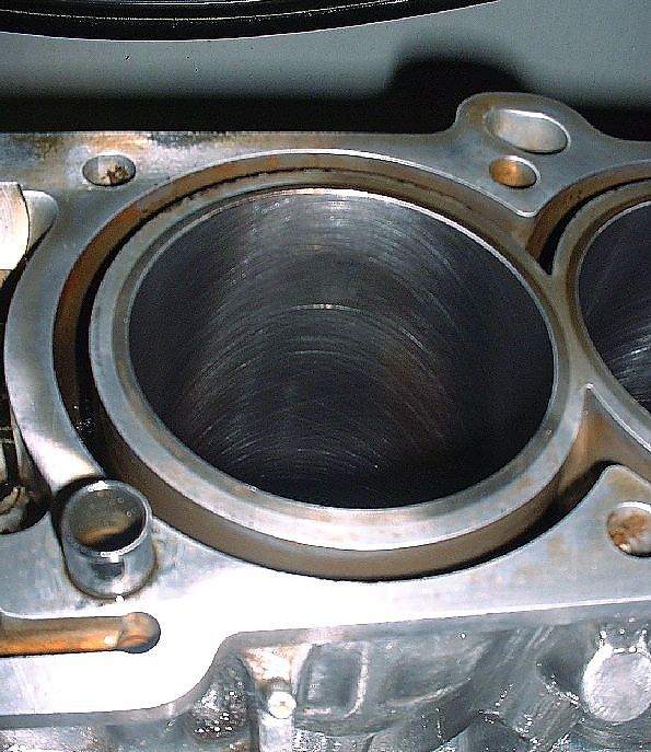
And here’s what a typical cylinder looked like up-close after it was done (albeit a little out of focus).
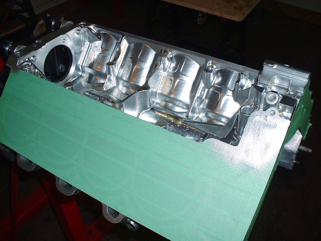
Once the machining, polishing and tweaking were done, the engine was finally ready for a good wash... I was getting tired of all that burnt oil-varnish ruining my photos anyway! I took the block to a different machine shop that specializes in rebuilding aluminium cylinder heads, which I knew from experience could wash the block in a high-pressure hot water and detergent machine that wouldn’t ruin my polished exterior. The results were great and the block came out looking better than brand new. Over the course of the next few photos you’ll see the difference.
Once the washing was done, I was finally able to start working on rebuilding the engine, starting with the lower end. The first thing was to measure the main bearing clearances, so in-went the bearings.
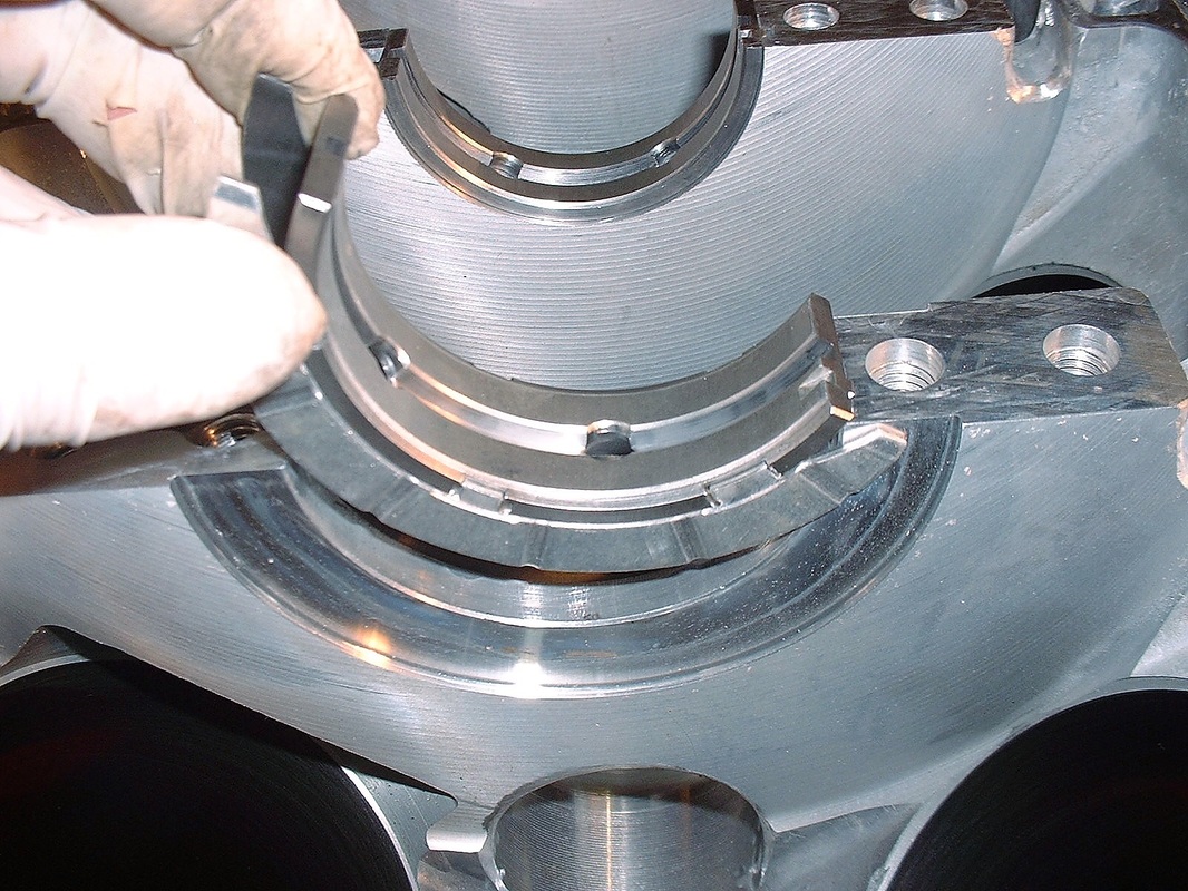
Here’s a pic of all the bearings in place (notice the clean innards?). Like any other engine, they go in the block dry. I lubed up the surfaces that contact the crank with a thin layer of motor oil before laying in the crank, but nothing thick like assembly lube at this point since I didn't want to throw off measuring the clearances.
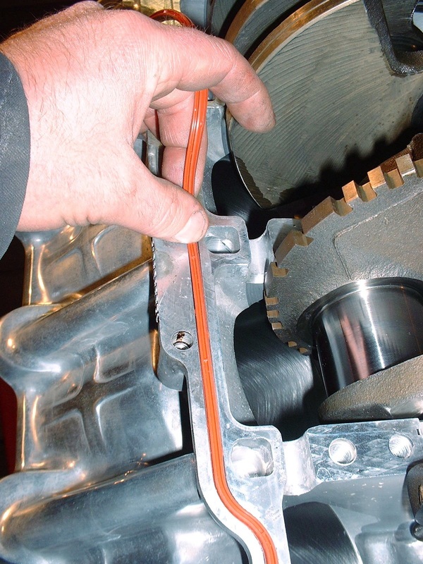
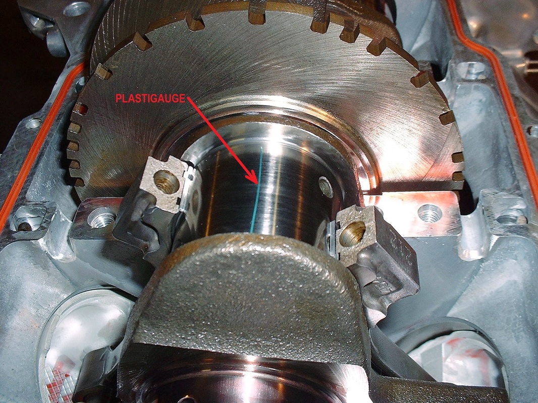
Next up was laying the OEM neoprene case-half seals and a piece of green Plastigage wax on each of the main crank journals. Then I inserted the old neoprene engine block seals to take into account their thickness so as not to throw off my bearing measurements. Later, I would discard these seals altogether and replace them with a new engine sealant that GM recommends instead:
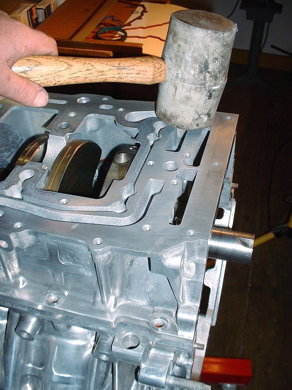
The other bearing halves were installed in the lower case, and the lower case was then installed carefully onto the upper half. There are four tight fitting guide pins that make installing the lower case difficult without a rubber mallet.
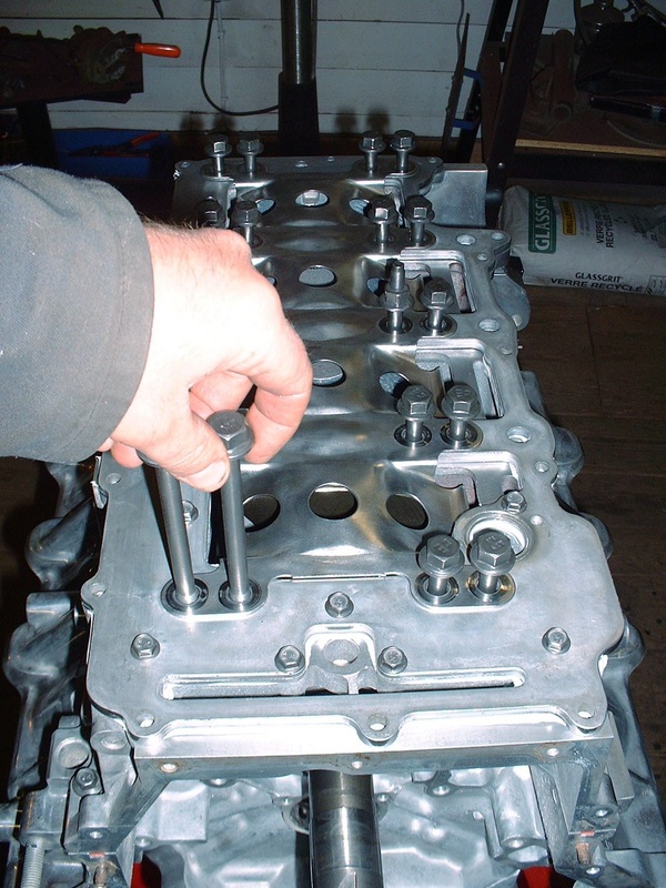
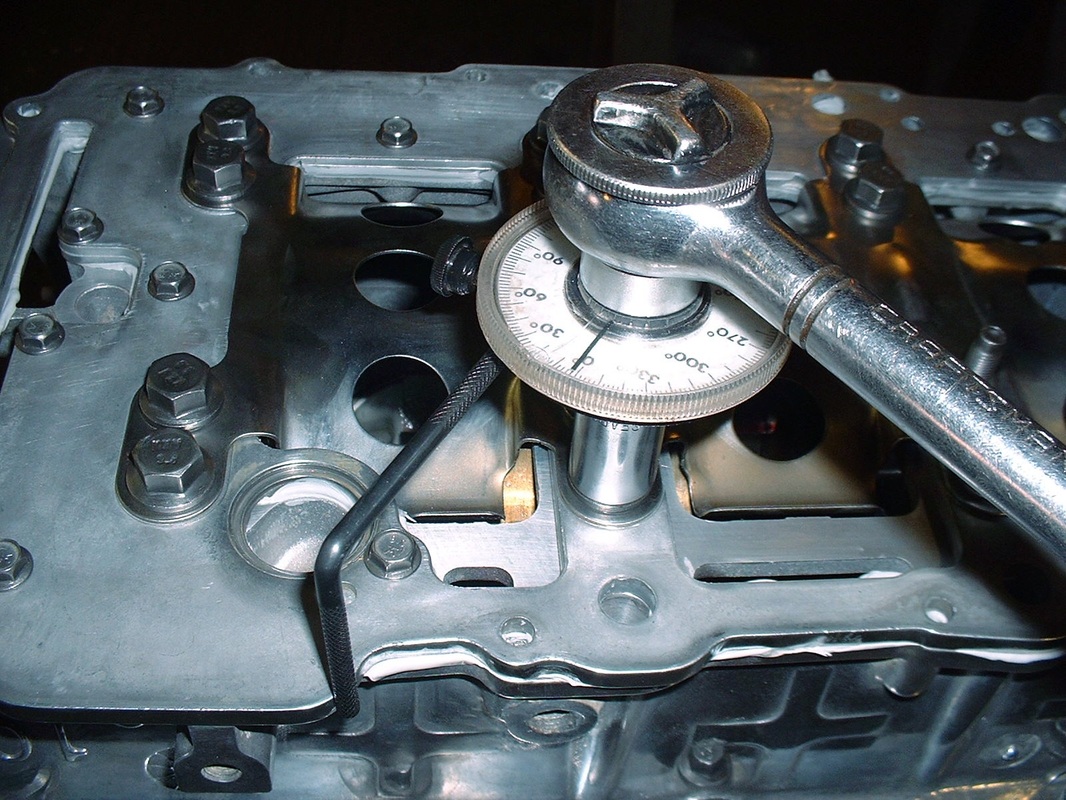
The Northstar engine has two bolts on either side of each main bearing, so there are 20 large bolts to install as well as a series of smaller perimeter bolts. Before the perimeter bolts are tightened, the main crank bearing bolts have to be torqued to spec:
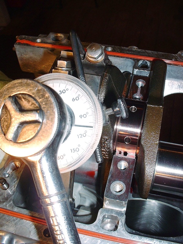
The instructions call for 18 lbft to be applied initially in a particular sequence, then followed-up by turning each bolt an additional 65 degrees. To do this accurately an angle gauge is needed on a ratchet wrench. For those who’ve never used one, they’re quite simple… they just attach between the wrench and the socket. There’s a little adjustable arm that sticks out to one side that must butt up against a steady surface like the side of the block, then once the gauge is zeroed, the wrench is turned spinning the needle the desired number of degrees:
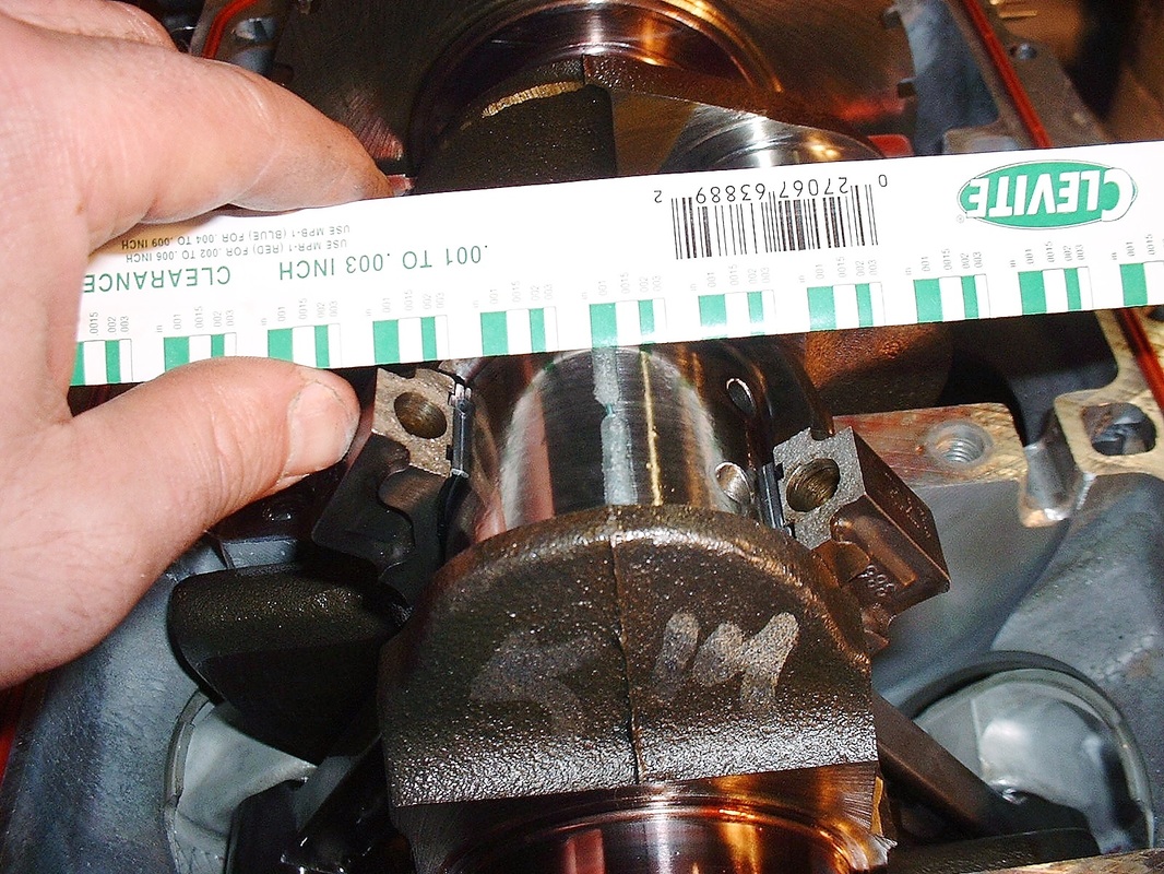
The Plastigage placed between the bearings and the crank gets squished into a line of wax which varies in width depending on how tight the clearances are. Once I took the lower engine case back off the block, I could measure the width using a little scale on the packaging for the Plastigage. The spec calls for 0.0006” – 0.0020” (yes… that’s six ten-thousandths) whereas mine measured from 0.0010” to 0.0015” so I was happy:
After cleaning the wax off the bearings and crank, next up was to repeat the process for the connecting rod bearings:
Before sticking the connecting rod caps on, there’s an important thing to remember when rebuilding a Northstar. The connecting rod bolts are Torque to Yield (TTY), meaning that they get torqued so much that they are irreversibly stretched the first time they're tightened, and then if they're removed, they’re no longer any good. It's a bit of a Catch-22. They also cost $17.14 each, and there are 16 of them. That equals $300 for a set after taxes, so I didn’t want to use up my new bolts to check bearing clearances. I reused the old bolts for this check, then tossed them out.
Once again, I installed the rod bolts, torqued them to 18 lbft, click on the angle gauge, set it to zero…
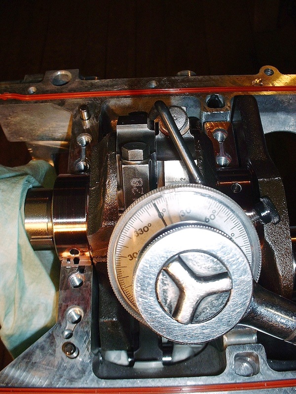
… and twisted the wrench until I reached a whopping 110 degrees more twist on the bolts. It not only sounded like a lot to me, it felt like a lot:
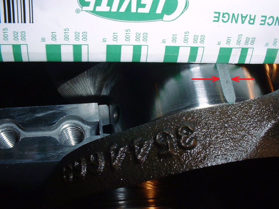
I could only do two at a time too, since only two connecting rod bearings were accessible at a time. So two by two I torqued the caps, removed the caps, checked the rod bearing clearances, cleaned off the Plastigage, turned the crank, then repeated the procedure for the next pair of rods. Here's more squished Plastigage right in the perfect range for the connecting rod bearings:
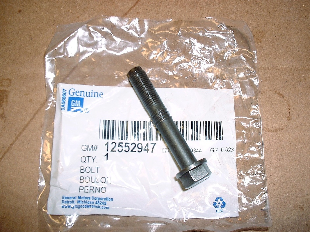
Lastly, here’s a pic of a rod bolt (GM p/n 12552947). I thought I’d include it because of the strange threads. It’s only the fine threads at the end of the bolt that engage the connecting rod, so I’m not exactly sure of the reasoning for the coarser threads halfway down. Just bizarre enough to make me reconsider going to the pro shop and buying some generic rod bolts at a quarter of the cost:

 RSS Feed
