Although I've given sneak peeks at the upgraded brakes in several previous posts, I haven't covered the details about them yet, so I'll do that here.
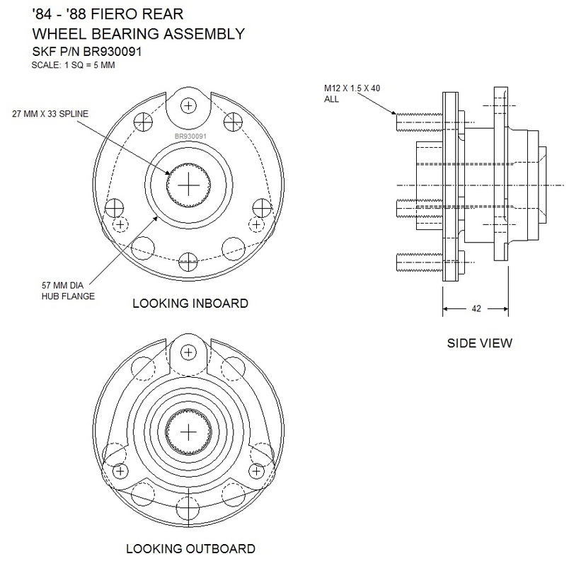
Any discussion about custom brakes has to start with the hub bearing since that's what the disk brake mates to. The bearing defines the mounting bolt circle specs, the offset between the knuckle and the brake mounting flange, and the diameter of the hub centring ring. Here's a drawing I created of the stock Fiero wheel bearing assembly with all of that information and more:
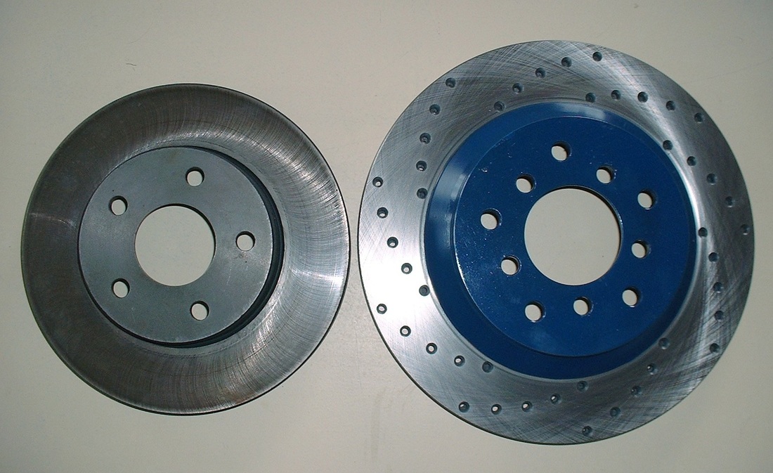
I decided to install 1988 – ’96 C4 Corvette 12” front brake rotors on all four corners of my car, along with the stock '88 Fiero callipers for now. The stock brakes on the ’88 Fieros are 9.7” diameter, so brake performance should improve since the callipers will be acting on the larger rotors with greater leverage. Practically speaking, I’ll have to wait and see how well it works out and upgrade to multi-piston callipers later if the performance isn’t up to snuff.
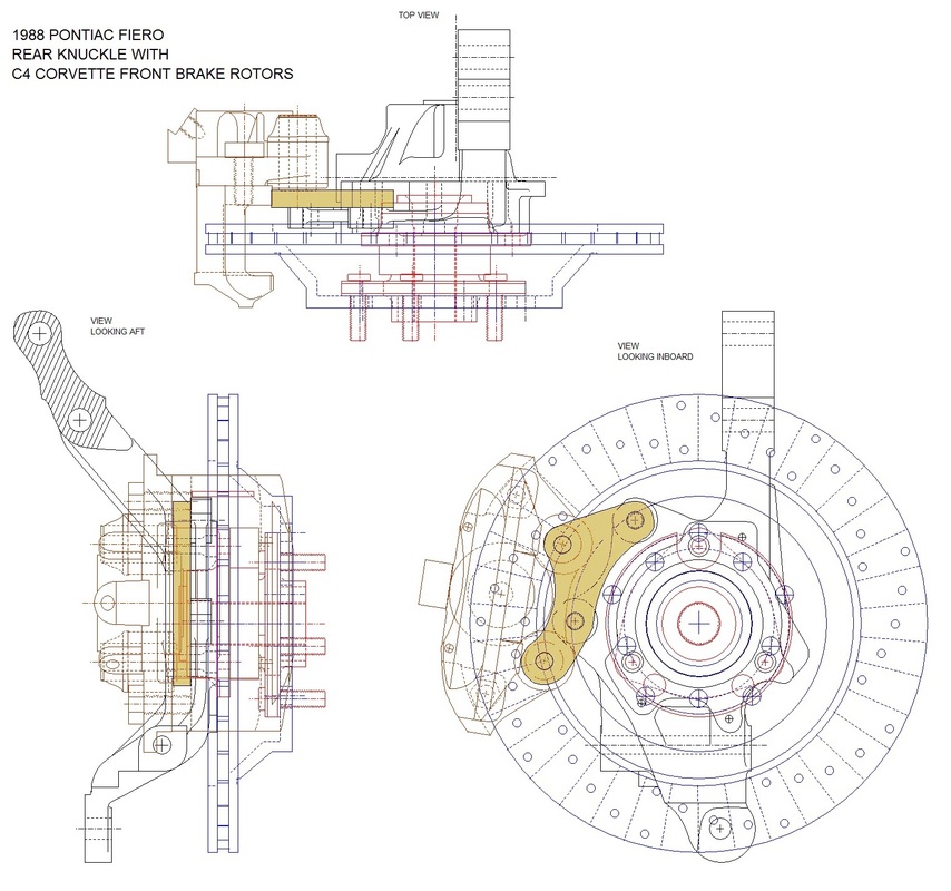
The larger diameter rotors meant that the callipers had to be moved radially outwards, and because of the different offset on the Corvette rotor, the callipers also had to be offset inboard to re-centre the calliper on the rotor. That was the job of calliper adapters (shown in orange):
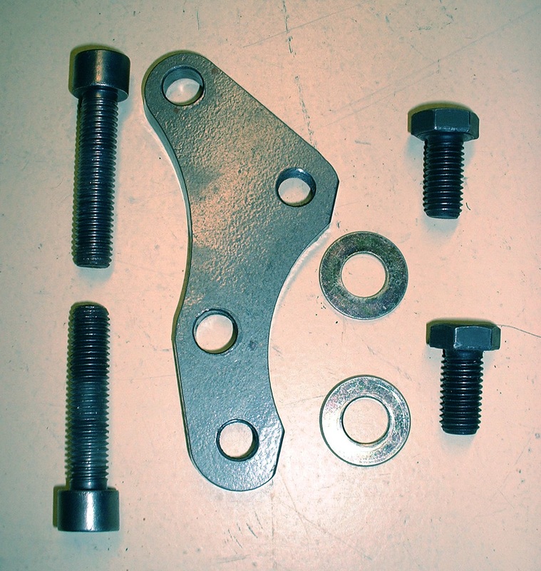
I bought mine from a company that is now no longer in business. This particular design ends up rotating the calliper so it's nearly horizontal. Other designs use countersunk mounting bolts and retain the stock calliper position, though countersunk bolts can be very difficult to remove after years of road use. Here's a close up of one adapter:
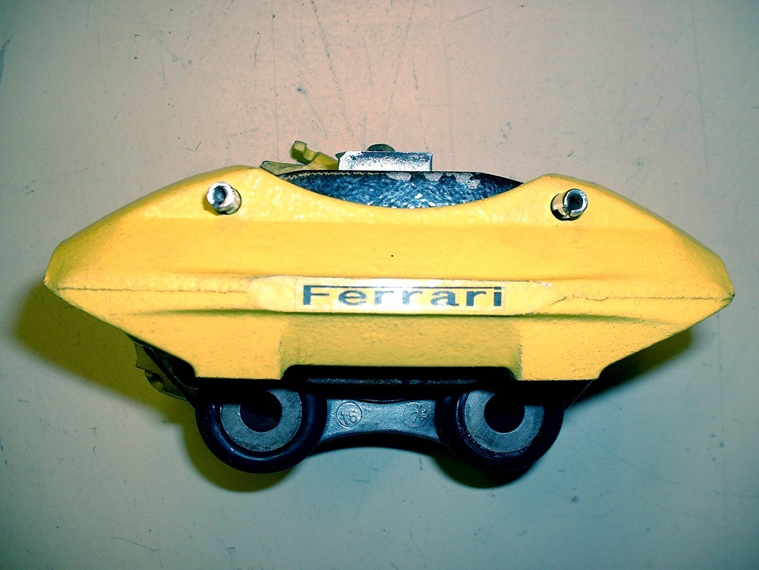
I bought a couple of calliper rebuild kits, new rubber slider boots, then sandblasted, primed, and painted the cast iron halves of the stock callipers. Then I cleaned up and polished portions of the aluminium calliper halves and reassembled them:
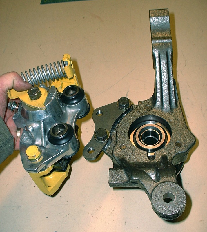
With the callipers completed, the next step was to install them on the knuckles using the adapter plates:
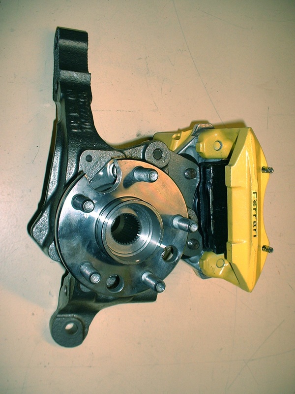
And here’s the street side... I find they almost look like four piston callipers... if you squint:
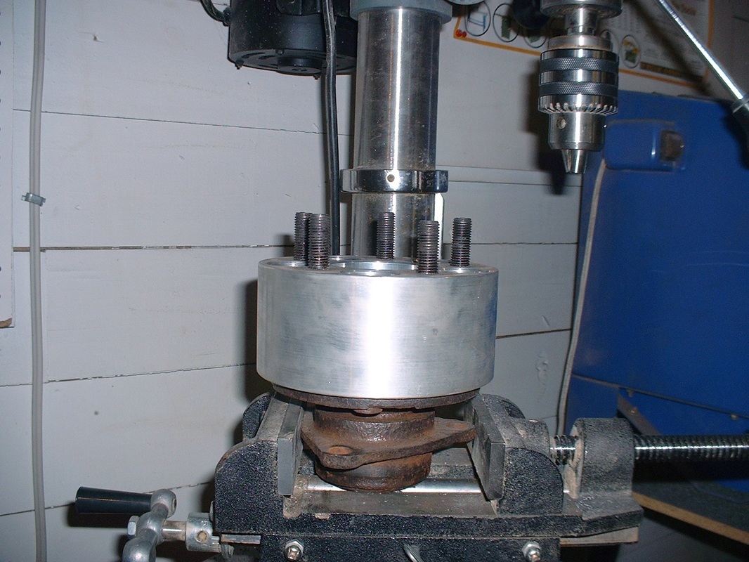
I won the rotors at the annual customer appreciation day at the local auto parts supplier, though I would have preferred cross-drilled ones. Corvettes have a 5 X 4.75” bolt circle so the rotors had to be re-drilled for the 5 X 100 mm bolt pattern of my bearing assemblies. I didn’t trust myself enough to re-drill the bolt circle so I took the rotors to the machine shop which cost me $20 per rotor. As for the cross drilling, I only needed a little ingenuity and a bunch of time to give them the look I was after. An old rear bearing assembly, an unused 3” wheel spacer, a level, and a drill press were the only bits of machinery I needed.
I’d never done this before but I figured since the rotors were free I didn’t have much to lose.
I figured out where the internal vanes were, then created a little drawing and a template to guide me:
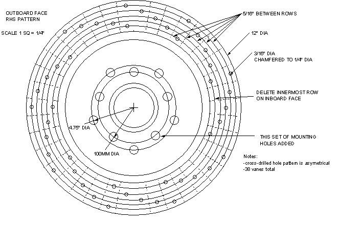
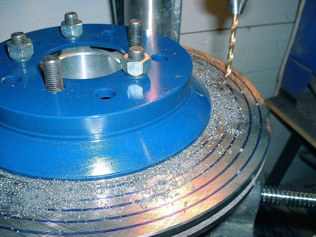
With the rotor lined up and level on the jig, I started drilling 1/8” pilot holes, then stepped it up to 3/16” after researching typical cross drilled rotors on the internet:
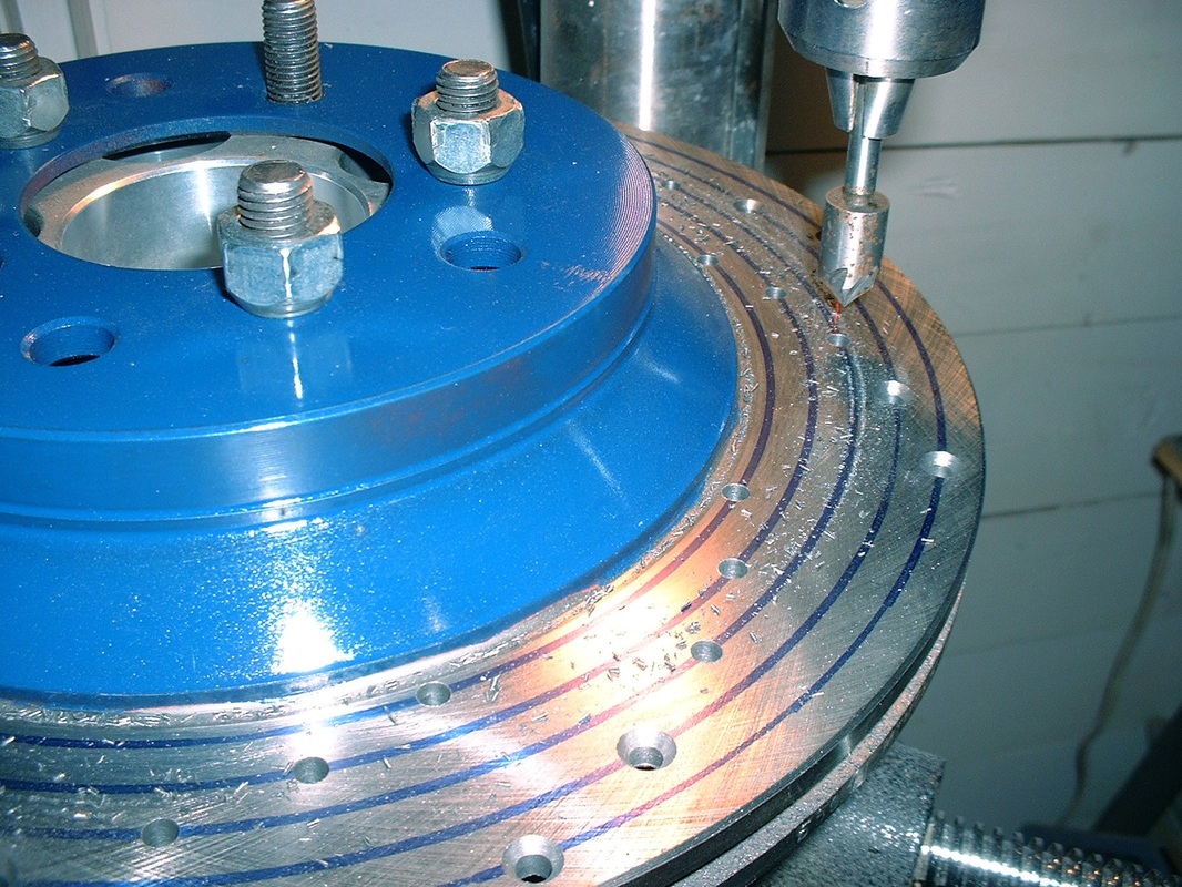
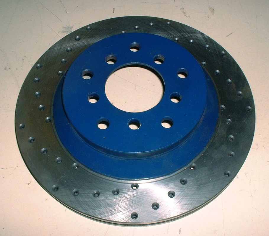
The final step was to chamfer all the holes to ¼” diameter, more for looks, but also to de-burr them and provide greater stress relief. For the previous steps, I drilled right through both layers of the rotor each time, but for the chamfering I had to do each side separately:
It took me 2.5 hours to set up the jig and complete the first rotor, then each rotor after that took 1.5 hours. It made for a long day at the drill press!
For the Corvette rotor to seat concentrically on the Fiero hub, an adapter ring is needed to up-size the lip on the Fiero bearing flange. I bought mine at the same time I got the calliper adapters from Fiero Addictions:
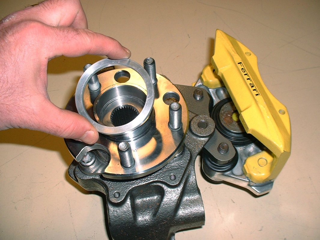
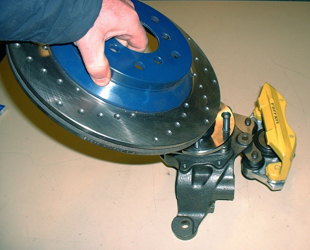
The next thing to do was slip the rotor on:
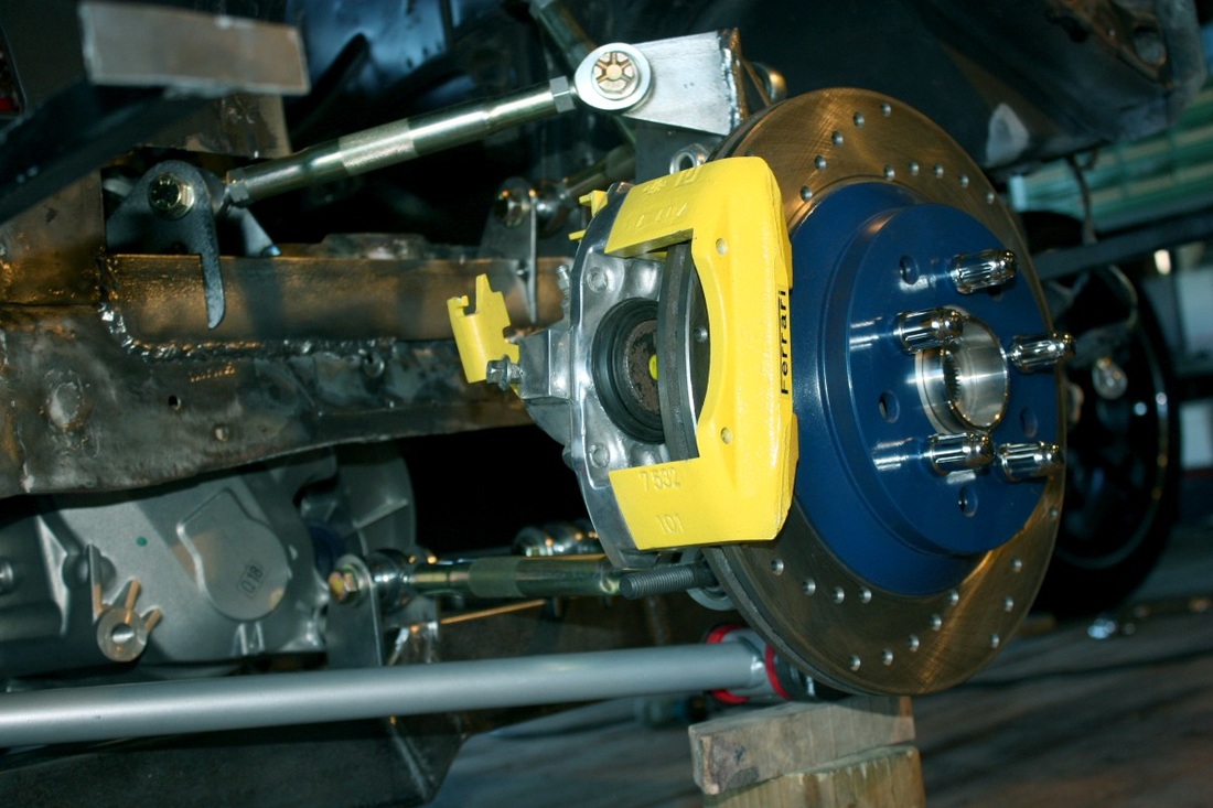
I still needed to install the pads, roll springs, and the wire bales, but that's pretty standard stuff so I won't go through it here. Here's what the final brake installation looks like:
Wheels and tires were next.

 RSS Feed
