In my last post, I divided the metal cowl into two separate chambers, a lower one for the HVAC inlet, and an upper for use with a relocated defroster system. I explained that the stock windshield defrost outlet needed to be relocated because the new extended windshield would have only had defrost air directed to the upper two thirds of the glass.
My new lower windshield frame was designed with integral defrost outlets at the base of the extended windshield, so this post is how I tackled getting hot air to those new outlets. I started by fighting the Hydra: the Fiero HVAC unit:
My new lower windshield frame was designed with integral defrost outlets at the base of the extended windshield, so this post is how I tackled getting hot air to those new outlets. I started by fighting the Hydra: the Fiero HVAC unit:
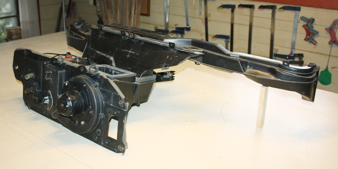
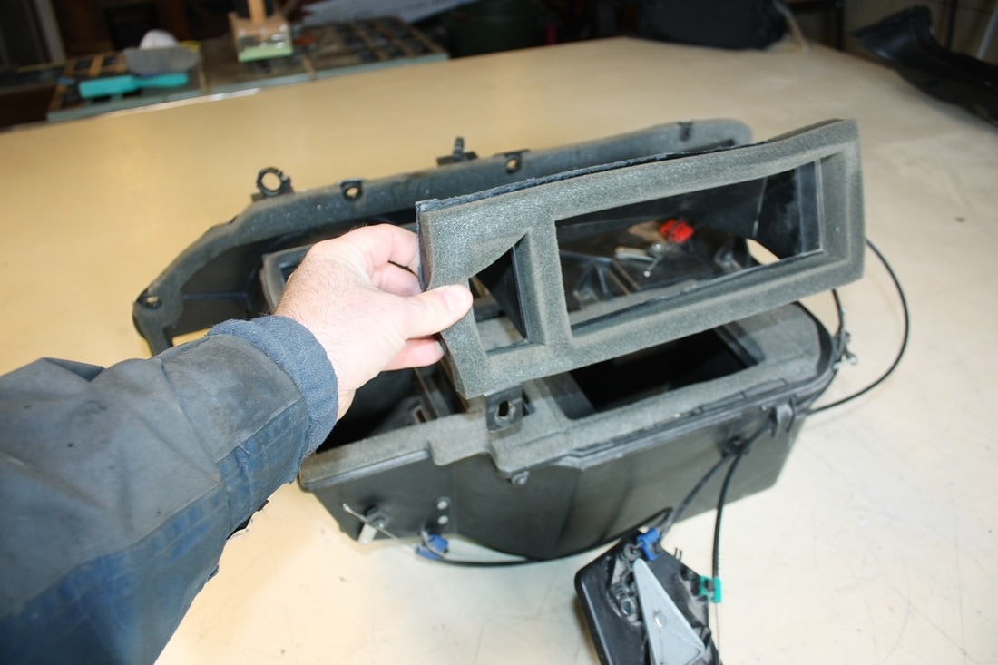
It's a monster with many heads and tentacles... but luckily, it's mostly modular. Here's the side view:
It's a monster with many heads and tentacles... but luckily, it's mostly modular. Here's the side view:
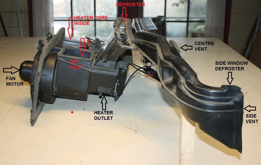
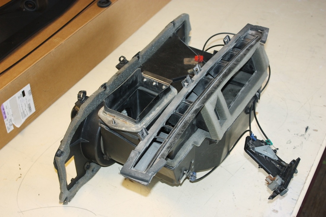
The entire side/centre vent system with its sprawling arms is held in place with only a few screws, so once it's removed, the HVAC unit with the defroster duct looks like this:
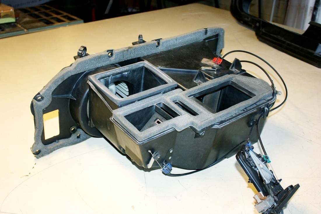
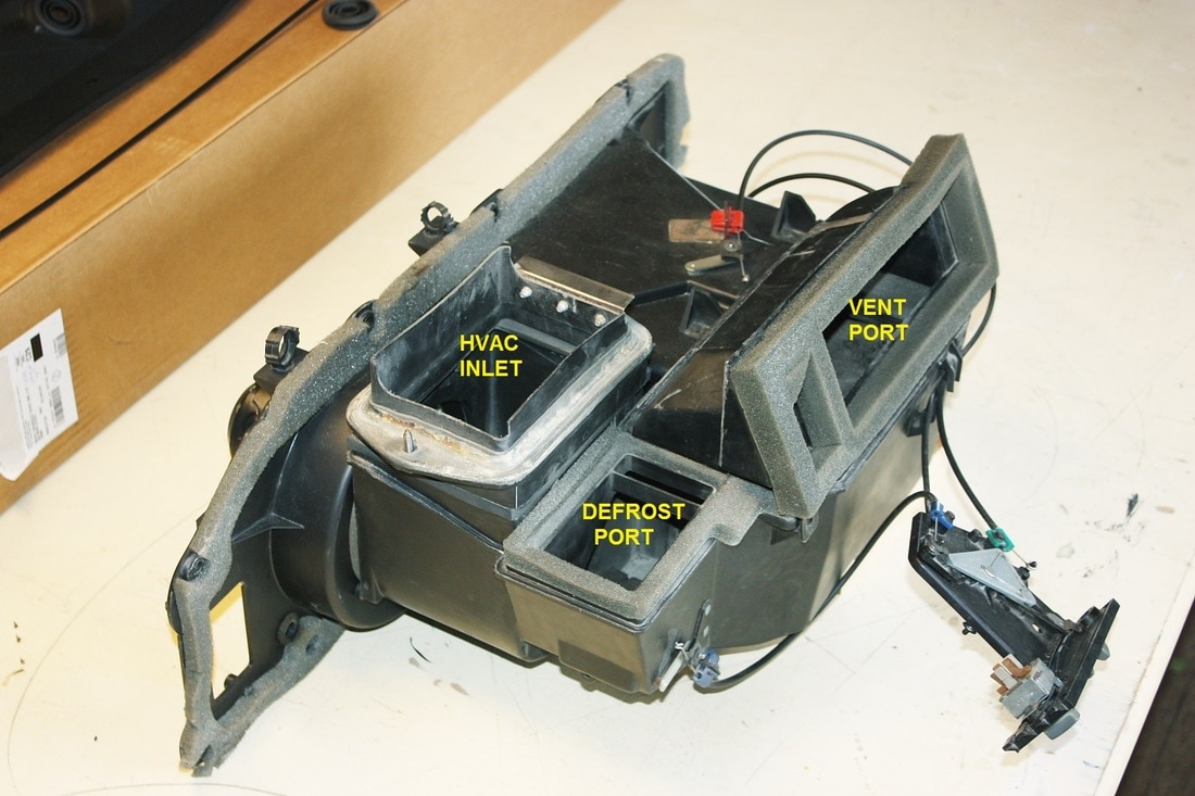
The defroster duct is also just bolted onto the main unit. Here's the main body of the unit with both the defrost and vent systems removed. I should mention that this unit does not have air conditioning... us Canadian country-folk would rather have the windows open!:
The defrost portion of the duct is not a stand-alone unit like the vent duct work. Although they're completely separate, the defroster is piggy-backed to a 45 degree elbow used for the vent system:
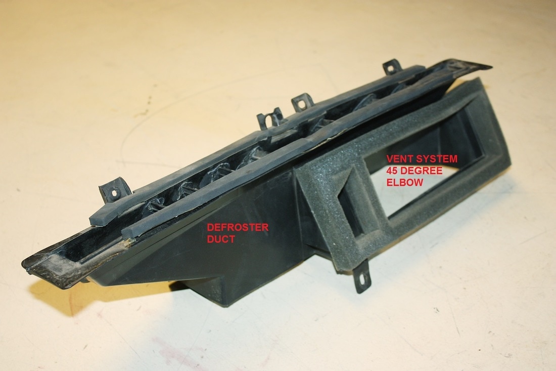
I needed to keep the 45 degree elbow if I wanted to use any of the stock central vent ducting, but I also needed to ditch the defroster duct. This was the plan:
By eliminating the stock defroster manifold, I'd be left with a rectangular hole in the main unit that I could tap for new plumbing.
After studying the stock defroster duct, I realized that with a few simple cuts, I could isolate the 45 degree elbow without much hassle. I used an oscillating saw to make quick and accurate cuts in the ABS plastic:
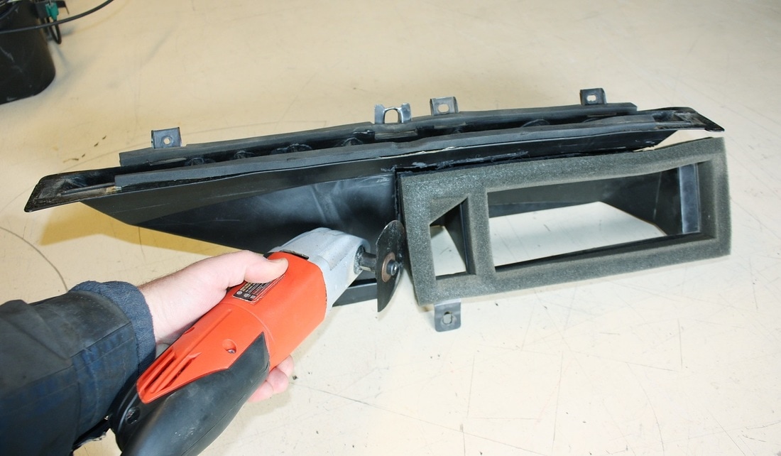
It was sure nice of GM to design this thing the way they did:
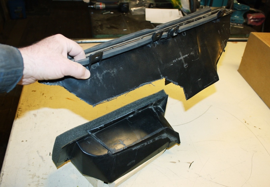
With that done, I could reinstall the elbow to the main unit...
... and have uncluttered access to the defrost port:
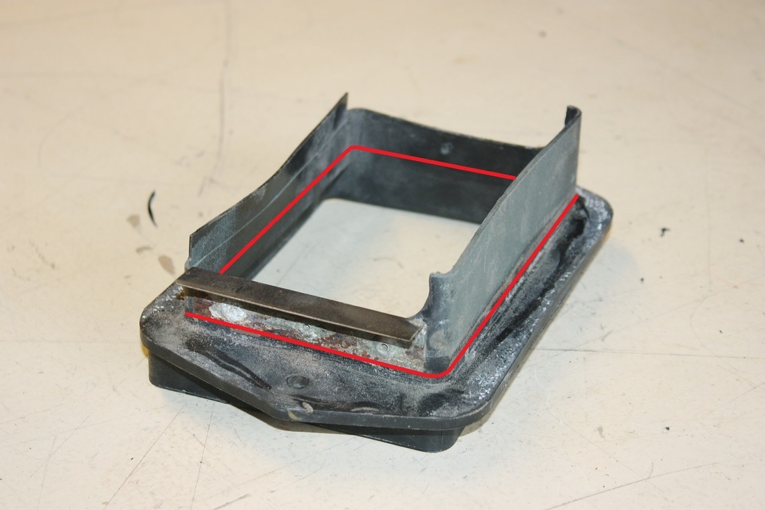
The last thing I had to do before reinstalling the HVAC unit into the chassis was to eliminate the water deflector on stock inlet adapter. The water deflector wasn't needed anymore because the convoluted path the air now has to take will prevent water from reaching the fan. Besides, the deflector would restrict the already narrowed inlet duct even further. I lopped off everything above the red lines:
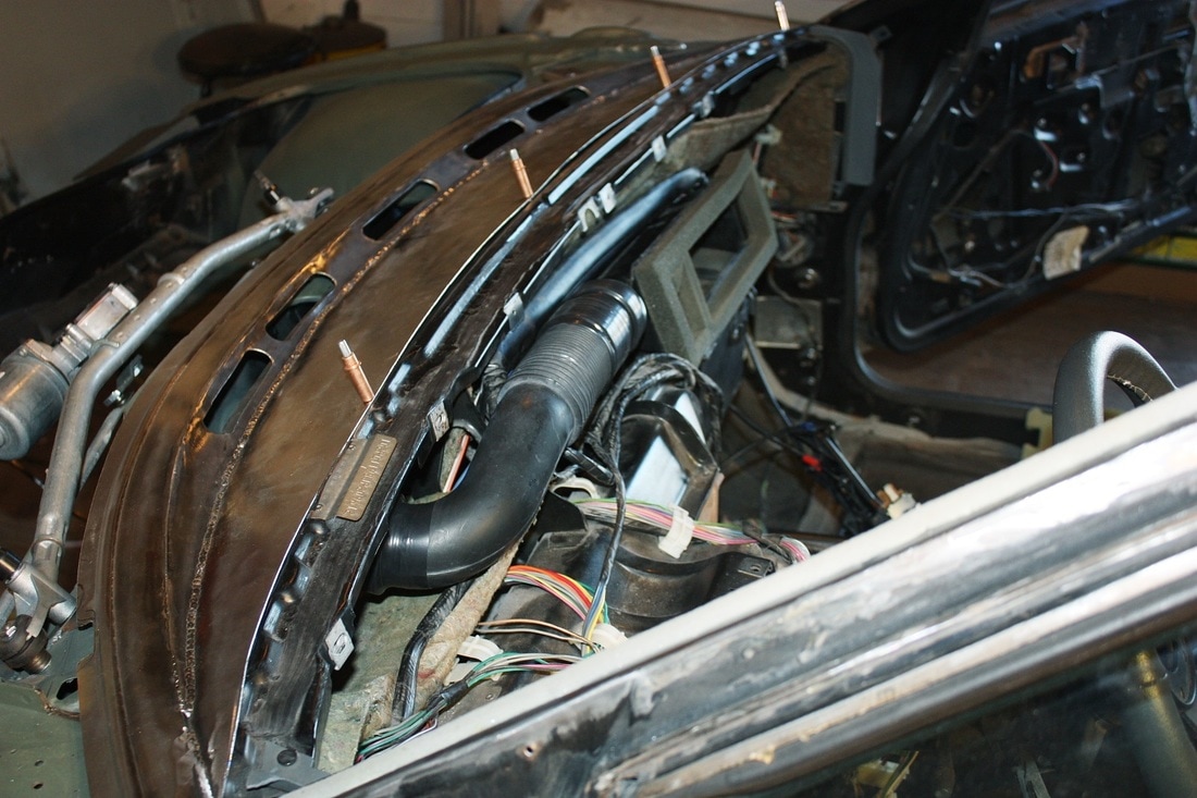
Once it was modified, it was the first thing to be reinstalled. This is the worm's eye view from the front compartment looking back through the hole in the cabin firewall where the HVAC unit normally sits:
Then I installed the main HVAC unit back onto the forward cabin wall in order to be able to plan the new the defroster duct work:
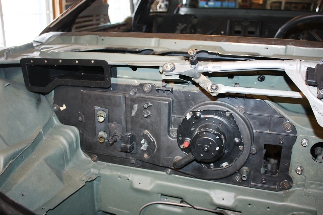
Here's all that shows of the unit from inside the cabin... the vent system port is in the foreground and the defroster port is in the middle of the photo:
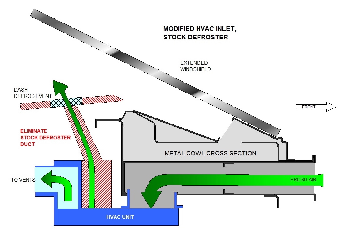
Returning to my diagram of the cowl and HVAC system, here's how my new defroster design routes the hot air from the HVAC outlet to the base of the windshield:
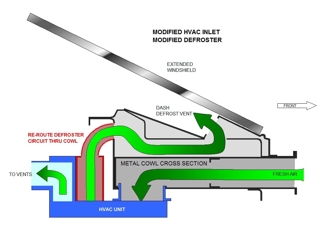
By making a hole in the aft wall of the metal cowl, I gained access to the upper chamber of the cowl from inside the cabin. From there, it was a simple matter of plumbing the hot air outlet of the HVAC to the hole.
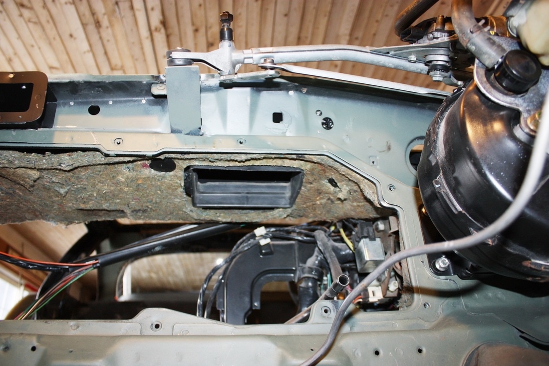
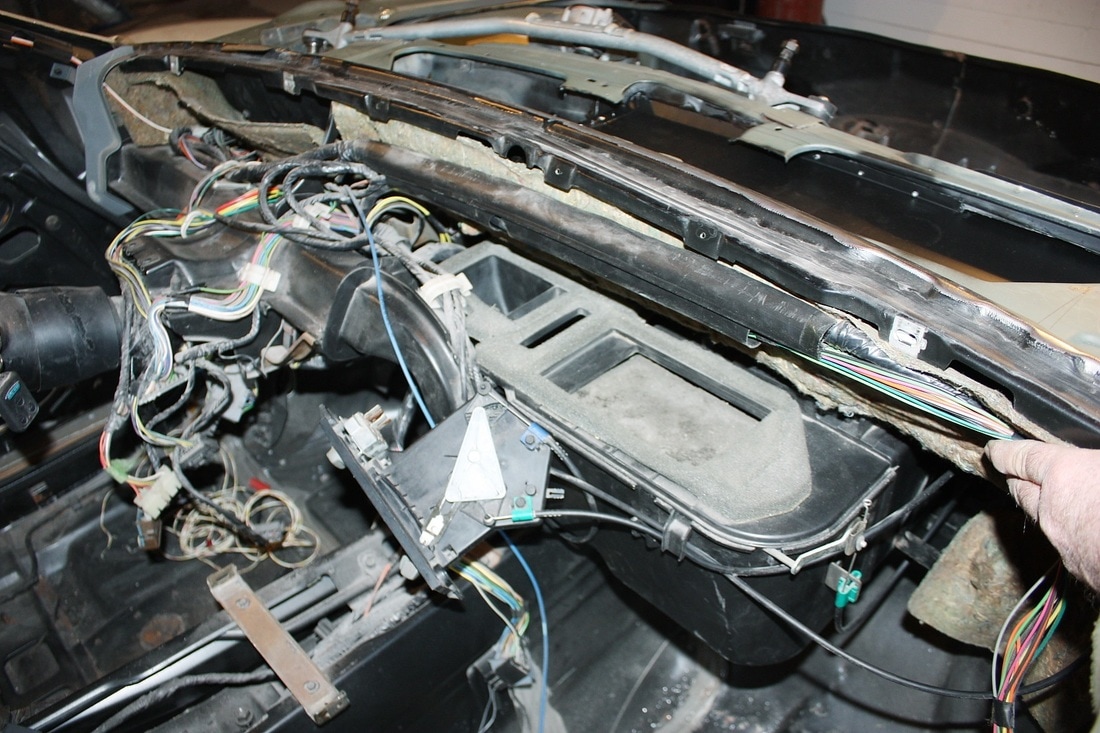
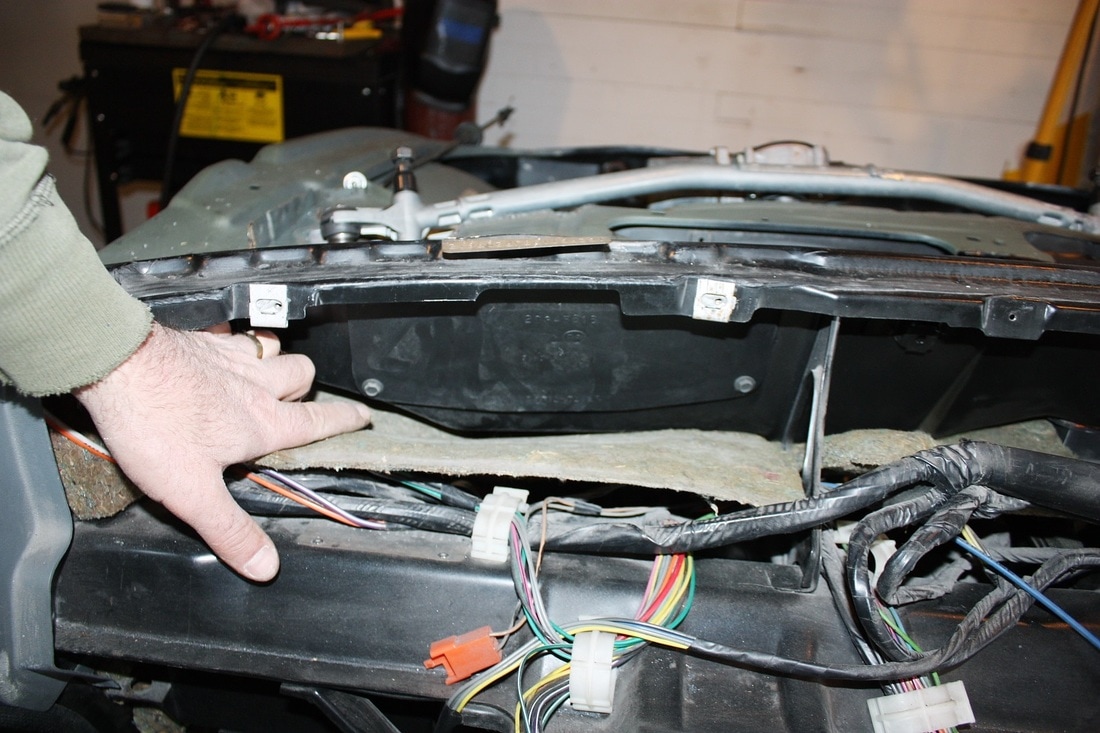
To access the aft wall of the metal cowl I simply pulled back the brownish sound deadening material from inside the cabin. I could drill a hole or series of holes anywhere along the length of this wall:
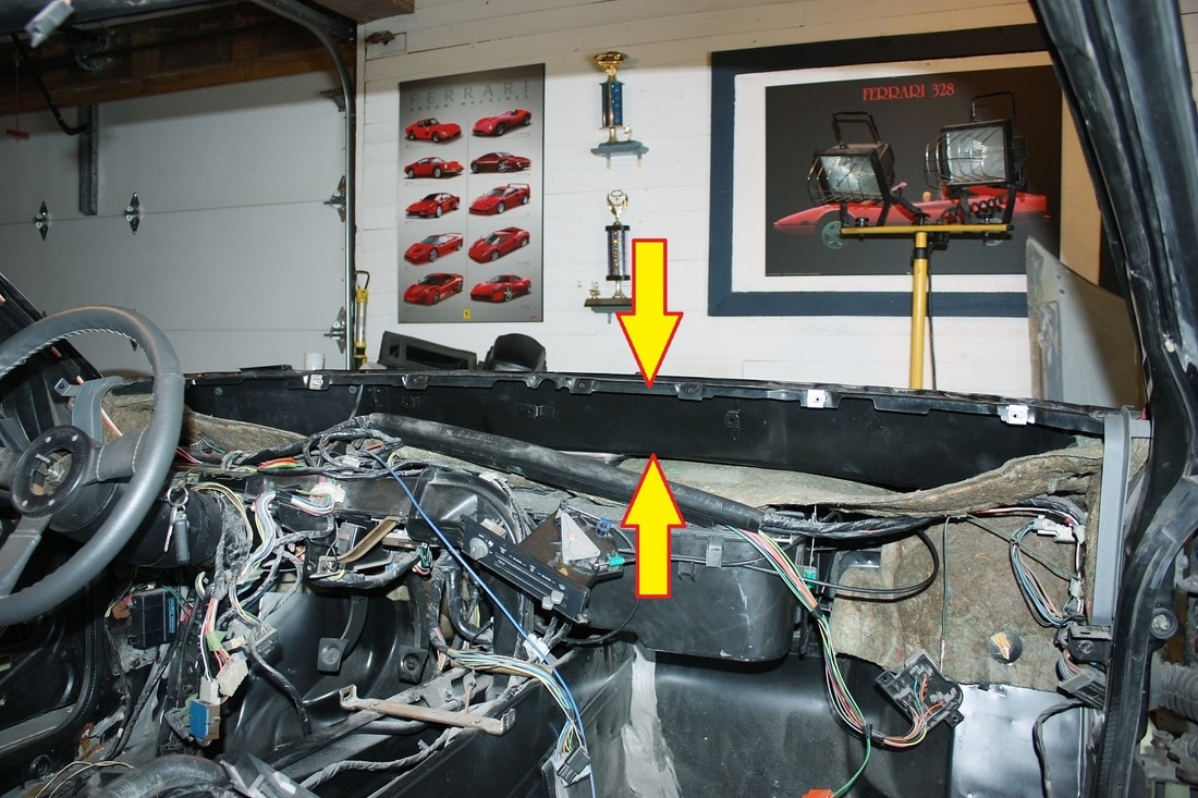
Interestingly though, I discovered an access panel right in front of the driver that I never knew existed. It was probably intended for maintenance of the OEM wiper mechanism, but with the new wiper mechanism no longer passing through the cowl, the port was perfect for my defroster system:
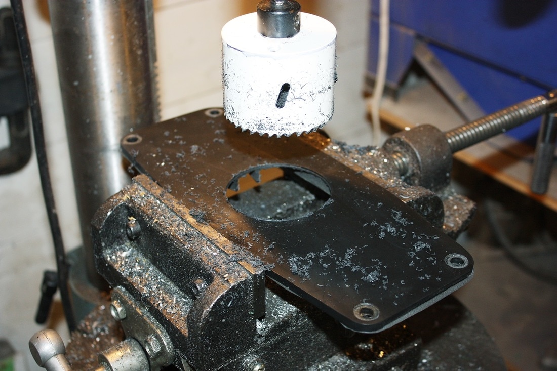
With the discovery of the cover, the rest of the plumbing design started to solidify. Since the cover was made of ABS plastic, it only made sense to build the duct work out of the same... gluing is always easier than welding! I bought some 2" diameter ABS sewer plumbing and used it to mark and cut the correct sized hole in the cover plate:
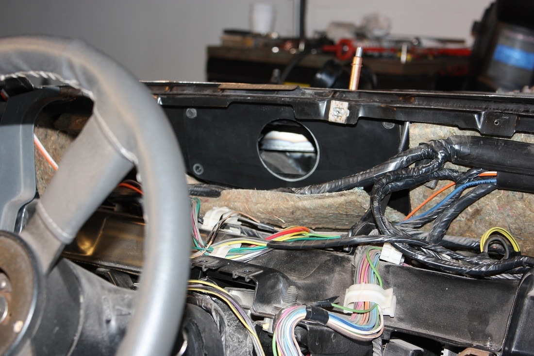
By reinstalling the cover plate, I could figure out the dimensions and route needed to bridge the gap between the HVAC defroster outlet and my new plenum inlet:
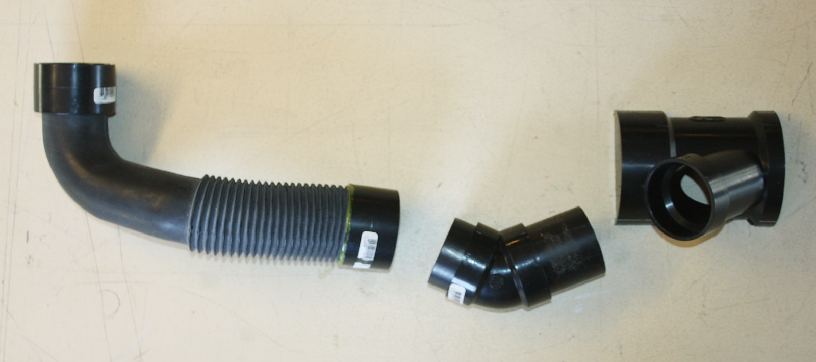
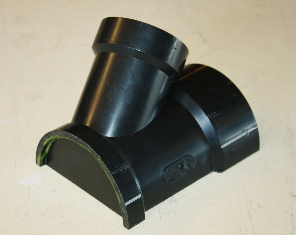
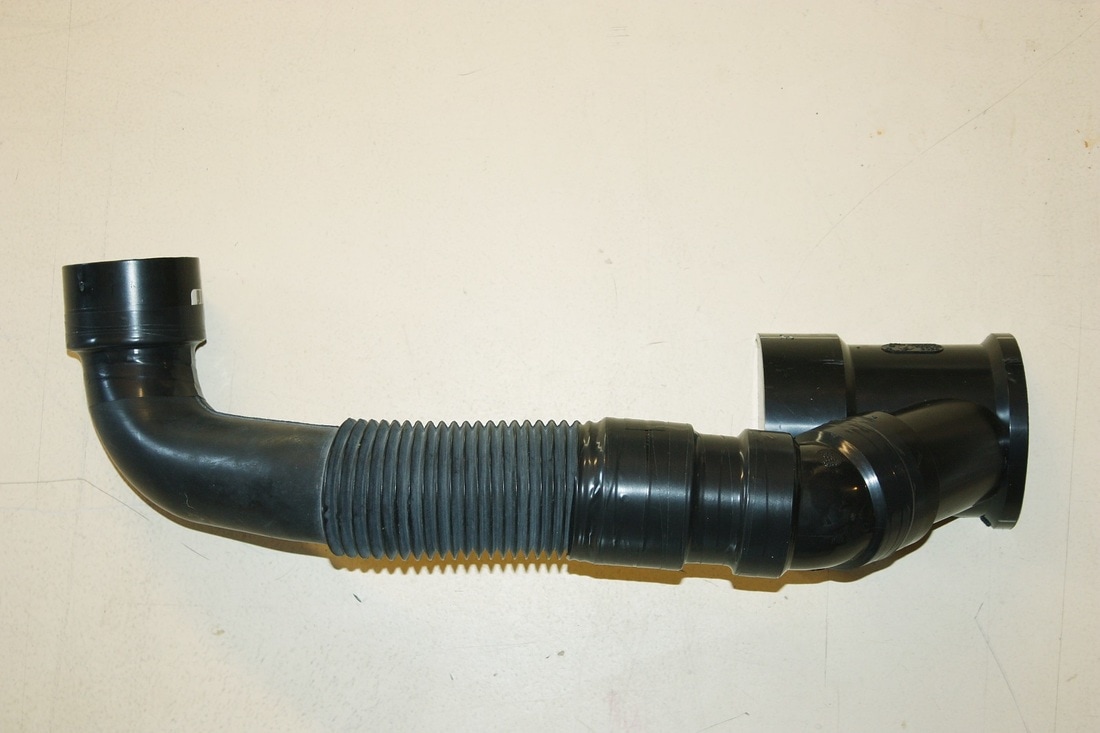
The rest was cobbled together with parts right off the shelf: a couple 2" ABS unions, a 45 degree elbow, and a 3"x2" Y pipe. The flex hose was an old part I had lying around from a Volvo, though I could have easily used a flexible sewer pipe coupler and some additional pipe:
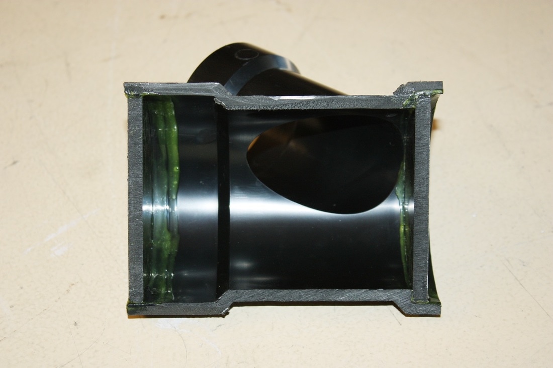
To make the tubular Y pipe mate with the rectangular HVAC outlet, I simply cut the 3" section in half length-wise and sealed the ends off with some flat ABS plate cut to shape:
 |  |
Here's the assembled duct work:
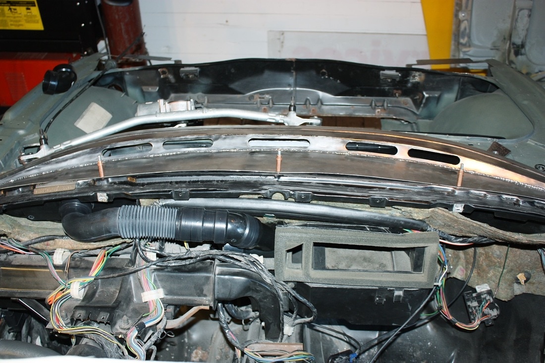
And here's how it fit to make the final connection:
I'll connect power to the fan and run it through the various speed ranges to make sure nothing in the system whistles, vibrates, or makes any other unwanted noises.
This pretty much wraps up the HVAC system mods that I'll cover in this chapter. The rest of the system will be covered under a new chapter on the interior.... but that's many months away.

 RSS Feed
