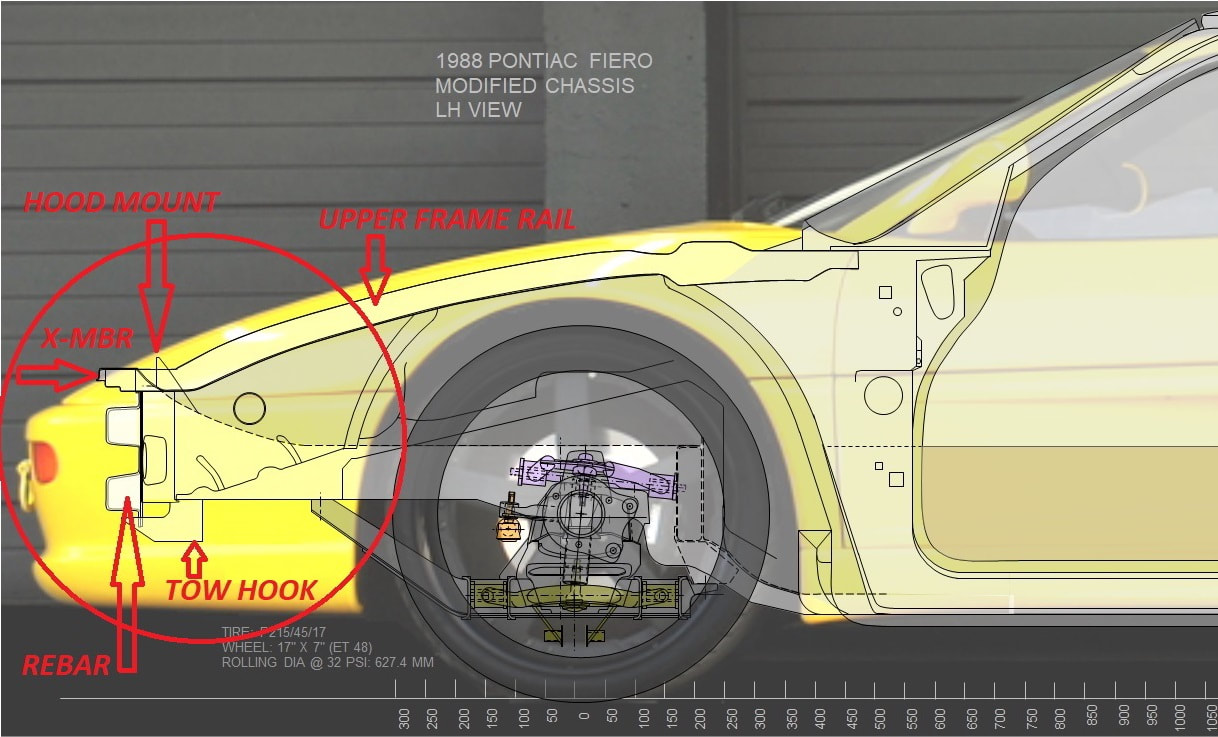
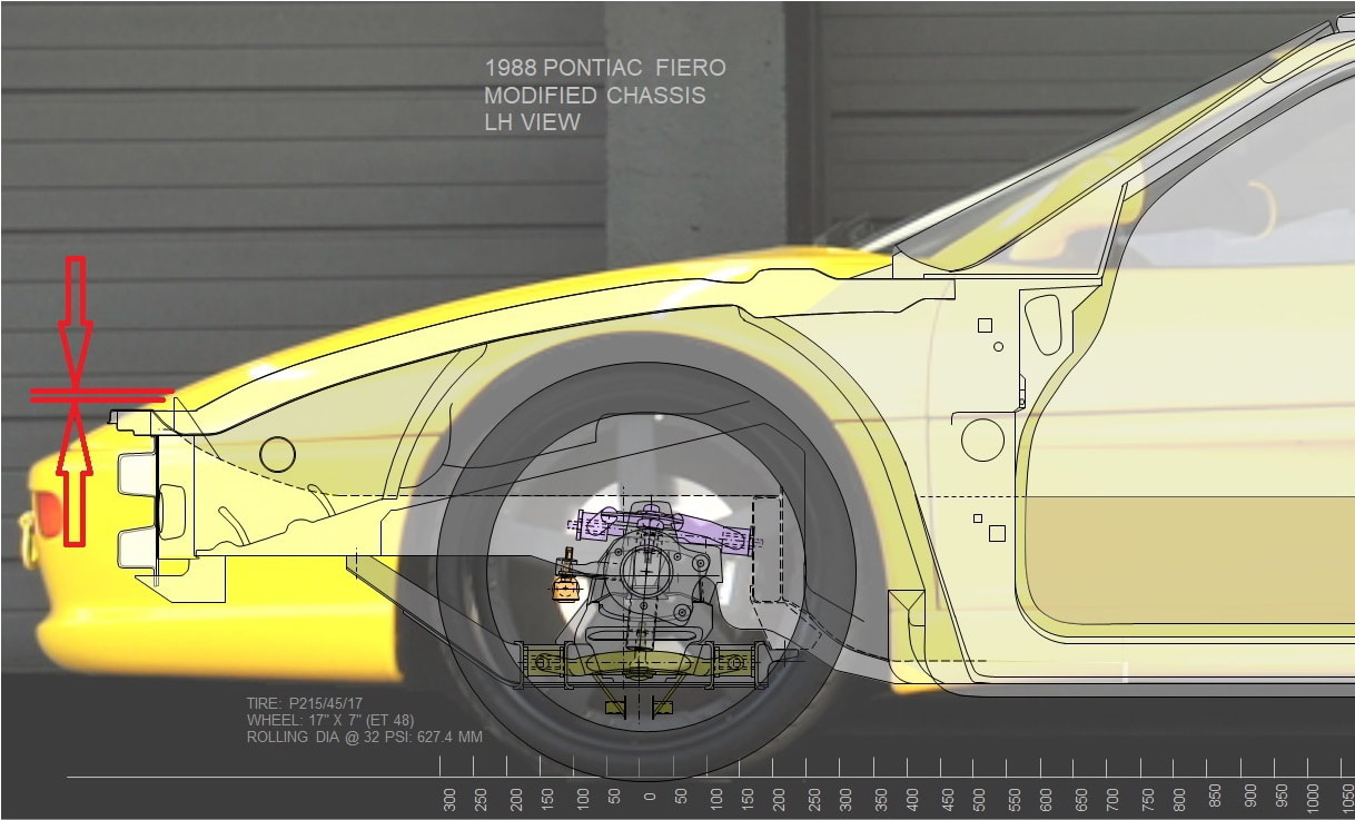
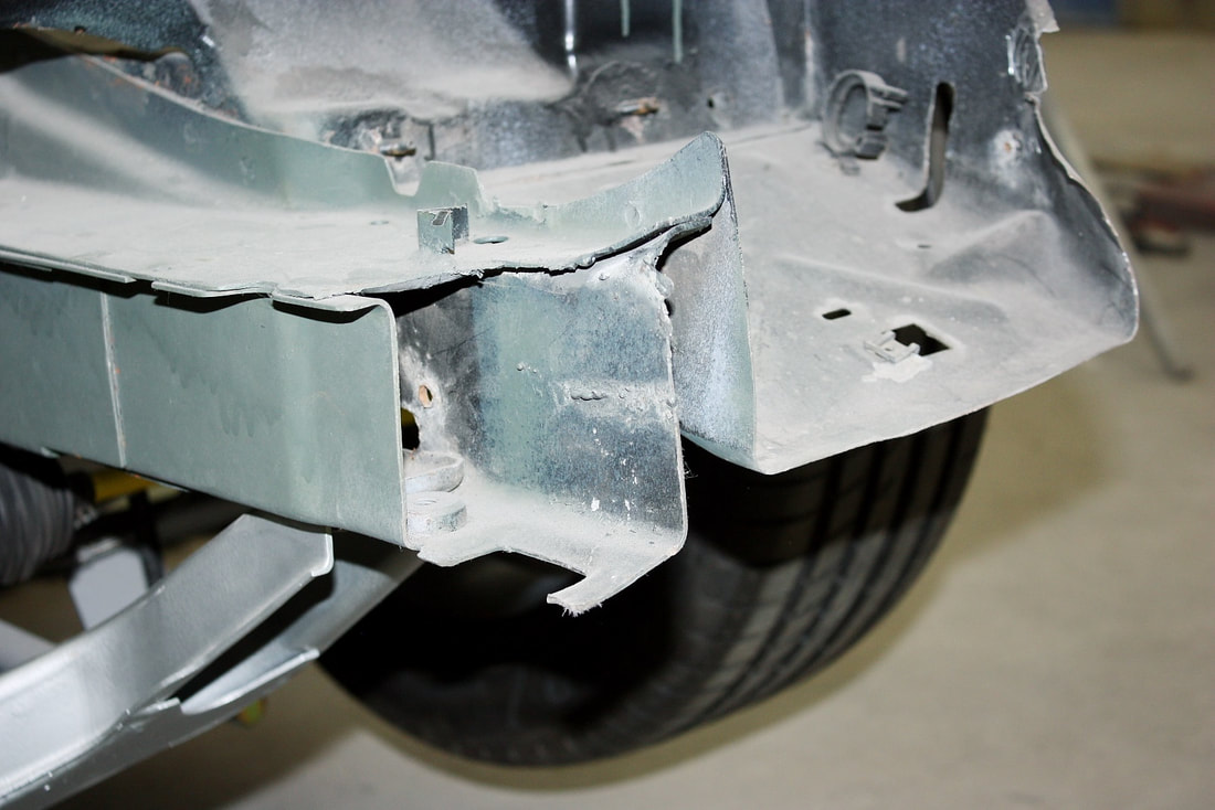
When I bought this partially started chassis and body kit, one of the modifications the previous owner had done was to remove and discard the front rebar (bumper), lop off 7.5” from the front lower frame rail, and about 10.5” from the upper frame rail including the upper front cross member. Doing so obviously left the entire front end (not to mention the passengers!) extremely vulnerable in the event of a collision:
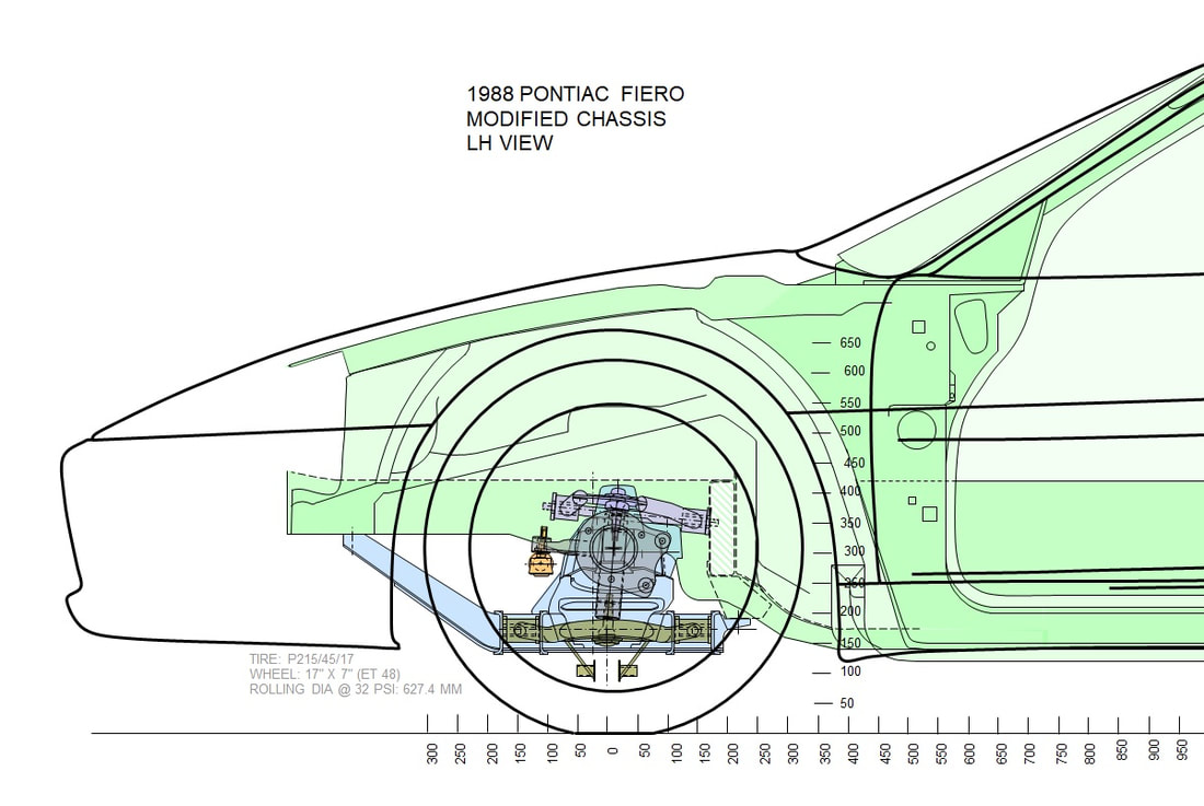
Surely if the frame rails were too high for the F355 fender and hood profile, he could have taken small pie slices out from the underside of each rail, re-arched them downwards as much as needed, and re-welded the rails to clear the body. I had no real way of knowing whether this would be possible since the parts were long gone, so I did my best to overlay a semi-scale photo of an F355 over my scale drawing of an un-cut Fiero frame to see where the interference might be:
Provided my IFG kit more or less followed the same contour as the actual Ferrari, the clearances looked close enough that it was worth investigating further. To do that, I paid a visit to my rusted out ‘85 parts car with the angle grinder in hand, and chopped off what I needed to reconstruct the front of the butchered ‘88:
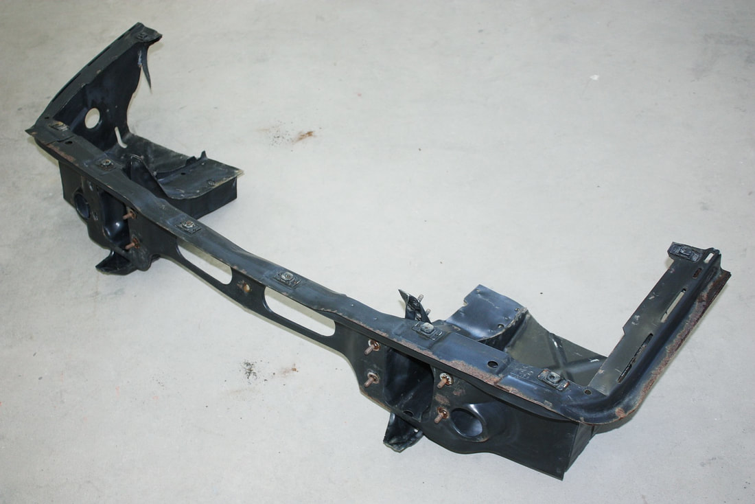
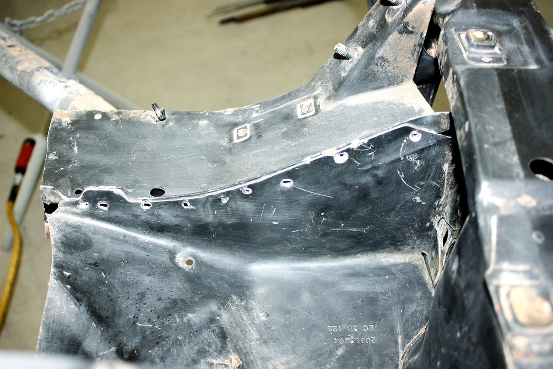
Here’s the ’85 front frame ready for some comparison measurements against my ’88 project car:
My plan started falling apart right from the get-go. One of the things I hadn’t realized from my drawings was that the upper frame rails, if re-attached, would interfere with the new headlights since they’re further apart than the stock Fiero lights. There was simply no way to save the front portion of the upper rails. I also confirmed (as my drawing showed) that the upper cross member was simply too high for the F355 nose. Since the cross member is held in place by the upper rails, and since the rails couldn’t be reinstalled, the fate of the cross member was sealed. I was starting to see why the previous owner lopped the entire chassis nose off.
I still needed frontal protection though, so I decided to see if the stock lower frame horns could be used. Of course they have the hood mounts and bumper bar mounts integrated into them, so reusing them would save work down the road. My drawing however showed the clearance to the under hood might be tight.
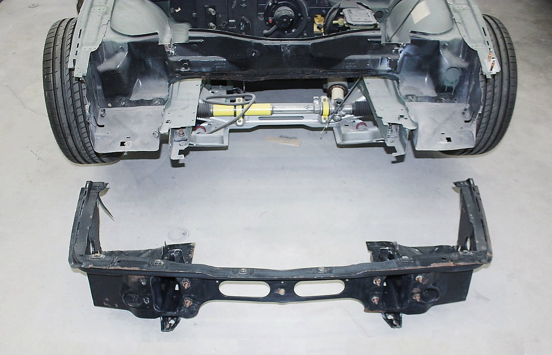
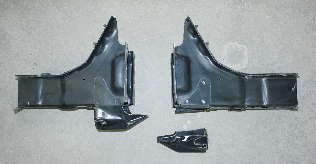
So I drilled out the spot welds holding the frame horns to the ’85 nose in order to give them a try:
It took a bit of work, but they came off cleanly. I also lopped off the tow hooks:
I mocked up one of horns onto the ‘88 chassis, then mocked up the front fibreglass clip to see if they’d stick up higher than the hood. My drawing ended up being bang on. There seemed to be just enough room for the hood mounts to clear the underside of the hood. There were drawbacks though… the hood mounts were too far back to be useful; I didn’t have a front rebar and would have to make one; and the frame horns could have been 6” longer, moving the rebar further forward to make more space in the front compartment:
Luckily, by the time I got to this point I had been working on the car for a couple months at a local collision shop to work on it there during the winter. The benefit of this became obvious when a 2017 Mazda CX-3 came in with some damage to the front end:
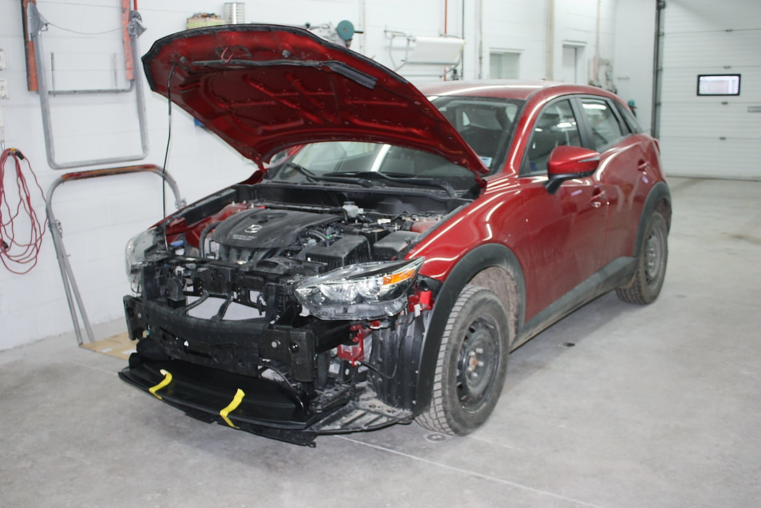
The rebar was bent slightly in one area and was unrepairable due to the nature of the metal, so it was discarded and replaced with a new part. The discarded rebar had integral frame horn extensions that looked to be about the right length for my car and weren’t damaged:
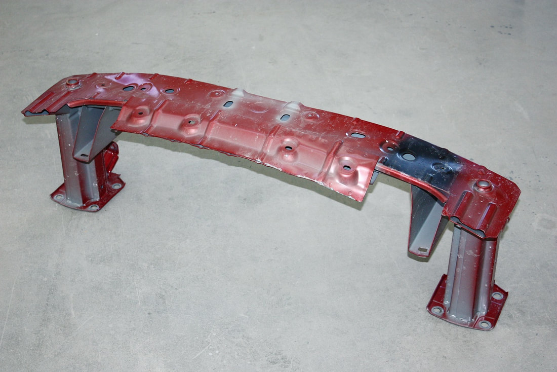
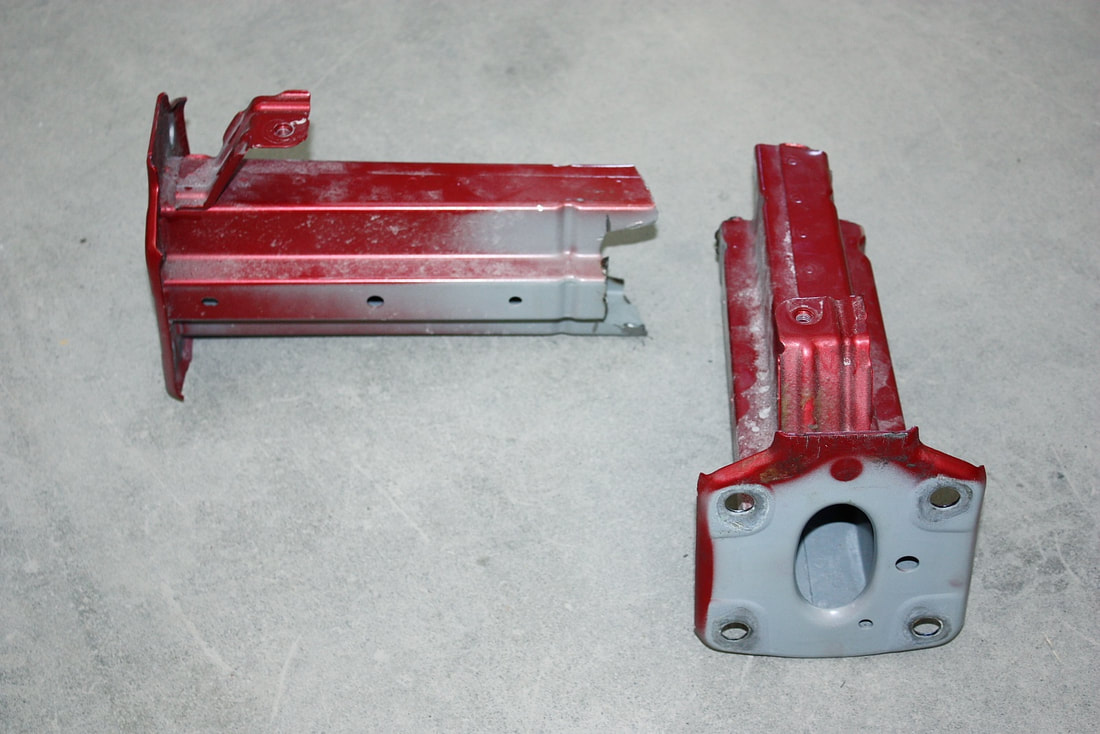
The unit wasn’t useable on my project as-is since the frame horn extensions were much too far apart to match the Fiero lower frame rails. So with a bit of elbow grease, I ground off the stitch welds holding the extensions onto the Mazda rebar, and was left with some interesting, bolt-on parts:
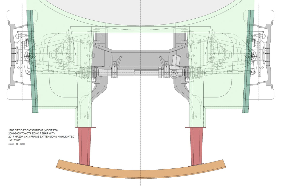
While measuring the suitability of the frame horns for my chassis, the shop owner joined in on the brainstorming and offered an unused 2001-2005 Toyota Echo front rebar to bridge the two horns. The three pieces seemed to be a near perfect fit:
The first thing I did was to square off the hacked up ends of my lower frame rails. I used the vertical beam of a laser level to be certain both frame rails would be cut to the same length and square to each other and the rest of the chassis. Here’s the ugly before photo:
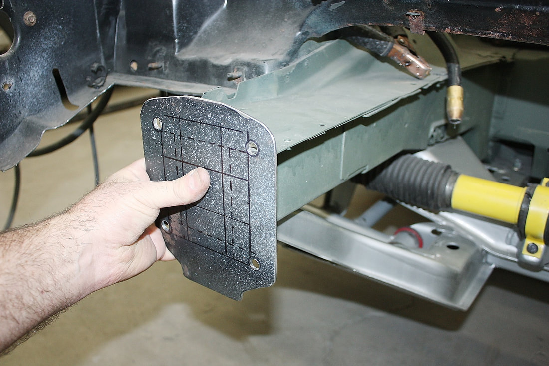
Next, I traced the pattern of the Mazda frame horn mounts onto some 1/8” thick steel plate, and cut out two end plates for the lower rails:
Once the end plates were welded to the Fiero chassis, I loosely bolted the Mazda frame horns to them:
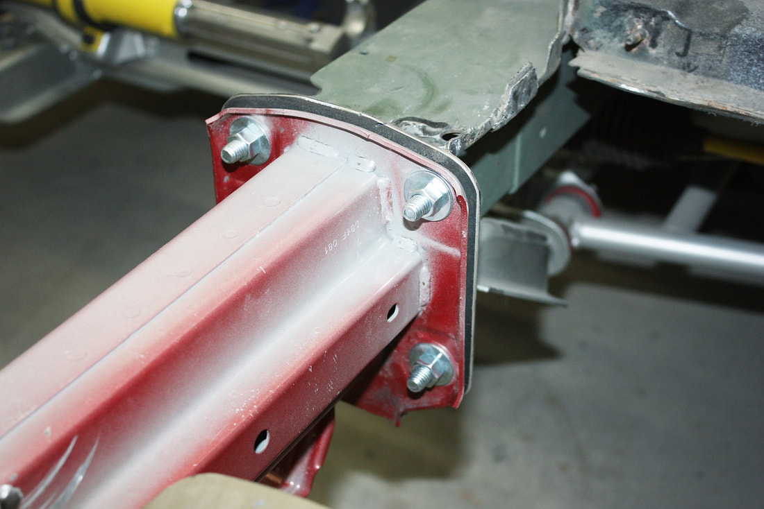
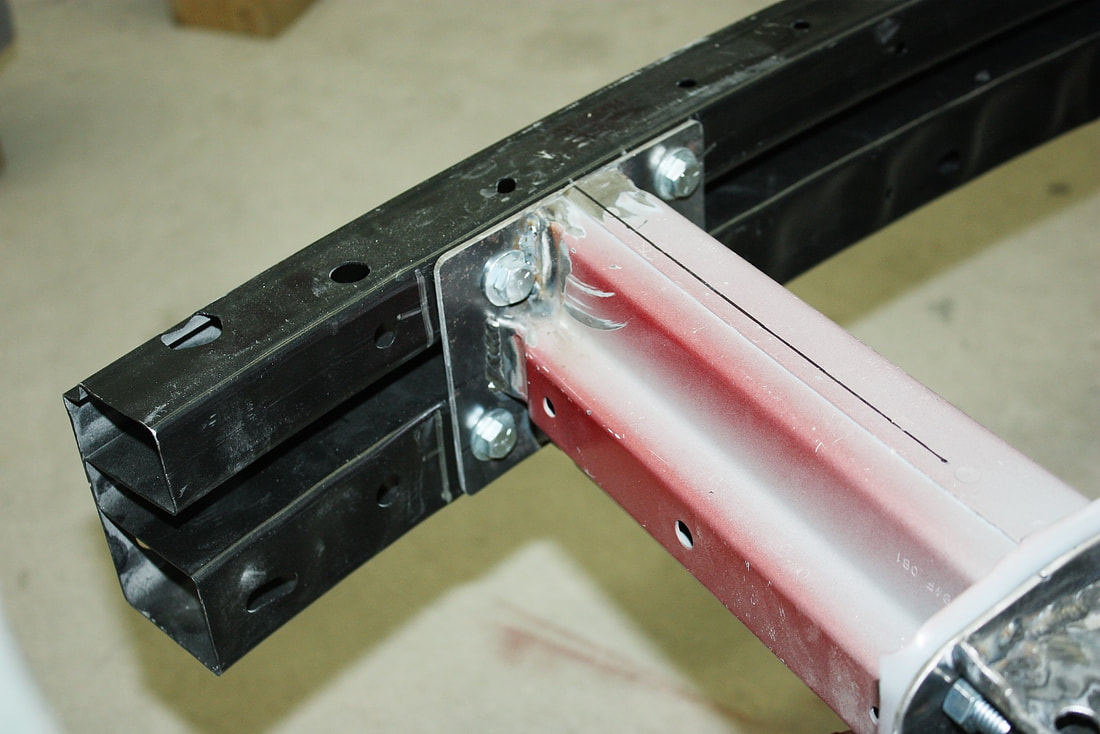
Then I trimmed up the front edges of the horns to follow the curvature of the Toyota Echo rebar. I could have welded the rebar directly to the new frame horns, but instead I decided to go “modular”. I cut up two more 1/8” end plates and welded them to the forward end of each horn, then clamped the rebar to these new plates:
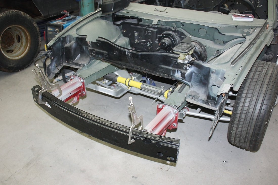
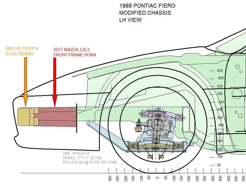
In cross section, the Mazda frame horns are taller than the Fiero lower frame rails, but about the same width. Rather than centering the horns height-wise on the rails, I chose to match the top surfaces and let the bottom ends of the Mazda horns hang lower than the Fiero’s frame. I did this for three reasons: the first was that it placed the rebar at the perfect height for the mounting tabs on the fibreglass front fascia:
The second was that at that height, neither the rebar nor the horns would interfere with the headlight mounting later on; and lastly, in a frontal collision, I felt with the horns mounted this way, they would likely crumple or break off downward under the car, rather than up and toward the passenger compartment. (Disclaimer: I’m not making any representation that my modifications are suitable for anyone except myself. I’m sure with some research, someone following in my footsteps could find modular frame horns from a different car that might suit their purposes better):
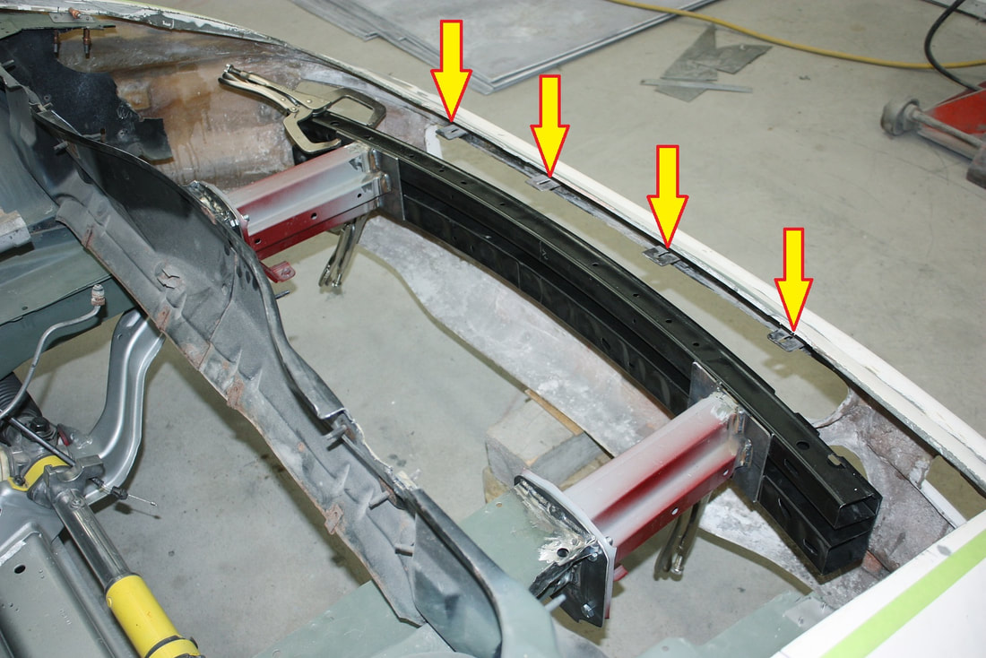
Once all the parts were aligned, squared, and levelled, I drilled bolt holes through the new plates into the back of the rebar, and fastened everything up tight. The eagle-eyed will notice I’ve used grade 5 bolts for now, but they’ll be replaced by grade 8 fasteners:
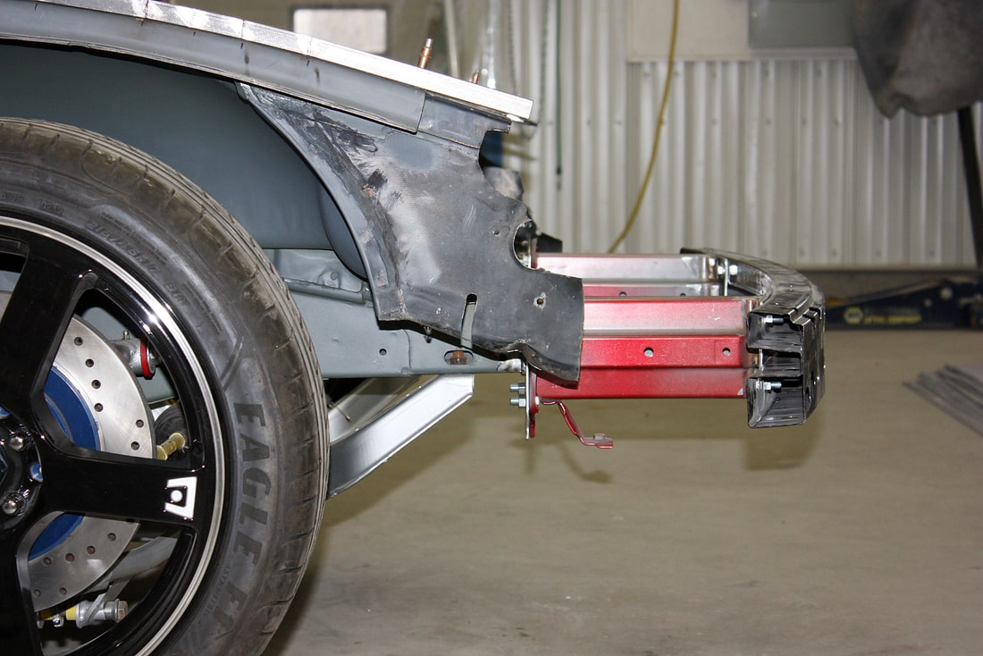
Here’s the side view of the finished front rebar installation:
In my home province, the Motor Vehicle Act states:
“All passenger cars and station wagons shall be equipped with a front and rear horizontal bumper of the same type and design as originally equipped, or equivalent, with the top of the bumper not less than fourteen (14) inches and the bottom of the bumper not more than twenty- two (22) inches, when measured, above the level ground surface.”
Provided this new rebar is deemed equivalent to the original design, it should also satisfy the height requirements since the top of the rebar will be at 17” above the ground at ride height. That’s 3” higher than the minimum. And the bottom will sit at 12”, which is 10” less than the maximum height.

 RSS Feed
