OK, so some of you might be wondering why I decided to include the exhaust system under the "Chassis" category. I could argue that the exhaust system is really no different than the cooling or fuel systems from the viewpoint of the powertrain, and many would have a hard time arguing the point. But the reality is that the order of the actual build activity doesn't always coincide with my neat little order of categories at the top of this page. So rather than having you bounce around between categories to find the latest updates, the exhaust system just became a "chassis" system in my books. Oh... and besides, squeezing a custom built Northstar exhaust system in a Fiero really does have more chassis than engine considerations!
It's amazing how the brain can work on solving several problems simultaneously. Several years ago when I first picked up my Northstar engine, I noted how the OEM exhaust system had some features that would probably be transferable to a Fiero installation, and other features that clearly wouldn't.
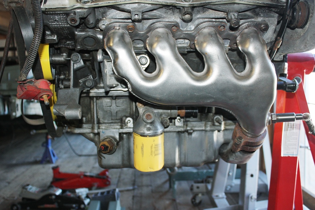
A couple of neat features were how compact the forward exhaust header was; how well-packaged the integral header heat shields were; and how a notch at the back of the oil pan was used to run one of the collector pipes to the other side of the engine without having the pipe hang below the oil pan. All of these characteristics are visible in this photo of my spare engine:
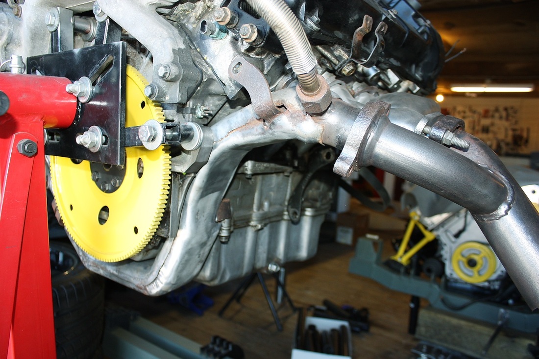
This next photo shows more clearly how the OEM forward collector pipe wraps under the oil pan notch, up the other side of the engine, arches over the enormous 4T80E automatic transmission (not shown), and merges with the collector from the aft header:
Here's a final photo of the aft OEM header showing the two collector pipes merging into the combined, single exhaust pipe:
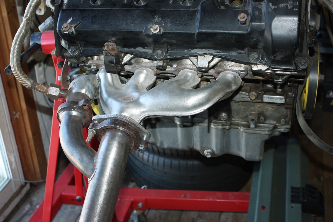
And that's where the no-so-desirable characteristics of the OEM exhaust system cropped up. The high and nearly horizontal exhaust pipe, in-line with the centre of the engine just doesn't lend itself well to the mid-engine Fiero chassis where space aft of the engine is at a premium.
So as the time approached where I had to make a decision about the exhaust system, my brain had been tossing ideas around for two years. I reasoned I could get a decent, compact exhaust by ditching the awkwardly angled aft header and crossover, and designing pieces that would keep the system down low. I would offset it to one side allowing space for a central muffler with conventional inlets and outlets on the ends.
Redesigning one header seemed half-baked though, so that idea progressed into potentially designing both into some long-tube, equal length headers for a little more power out of the engine. Then that idea morphed into speculating whether a 180 degree long tube, equal length header system could be fit in the existing space. (I won't go into detail about what 180 degree headers are, but suffice it to say that by pairing the two outer cylinders on one head with the two inner cylinders on the opposite head into a single 4-into-1 collector creates a series of exhaust pulses that further enhance power. The cylinders that need to be paired depend on the type of crankshaft and the firing order.)
The only way to test whether any of these ideas were even possible within the limited space I had was to try mocking them up. I figured I'd start with the most complex system first, and scale back to lesser complexity if I ran into insurmountable roadblocks.
The first thing I needed to do was determine what diameter to make the primary pipes. My research uncovered the following equation:
Primary Pipe Area = Peak Torque RPM X Volume of 1 Cylinder in ci's / 88,200
= (5000 RPM X (280.7 ci / 8 cyl)) / 88200
= 1.989 sq-in
I decided I'd like to see peak torque at 5000 RPM so plugging the primary pipe area from the above equation into this next equation led to a primary pipe diameter:
Pipe Dia = 2 (sqrt (Pipe Area / pi)
= 2 (sqrt (1.989 sq-in / 3.1416)
= 1.59"
Stepping up to the closest available pipe size meant 1-5/8" diameter primaries.
With that bit out of the way, I went shopping for some cheap alternatives to using expensive mandrel bent steel pipes for my mock up phase. It turned out that 1-1/4" black ABS sewer/vent pipe happens to have a 1-5/8" outside diameter. Coupled with available elbows in 90, 45, and 22.5 degrees, the ABS was going to be like a poor man's Lego set. Even better: the centreline radius for these plastic elbows is 2", which is a radius that just so happens to be available in steel elbows as well.
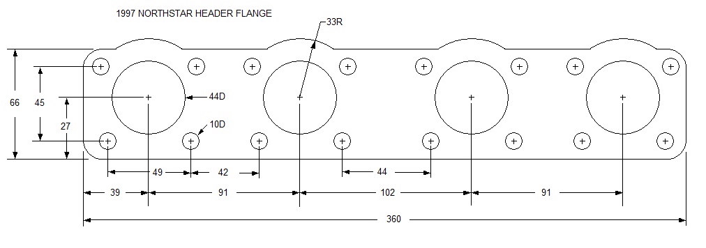
Next, I needed something to use for my mock up header flanges. No one carried ABS sheets in 1/4" to 3/8" thickness around here, so I popped by the local glass shop and bought a piece of 1/4" thick Lexan. Then, using my new exhaust gaskets as templates, I measured and drew out the flanges in case I ever needed the data:
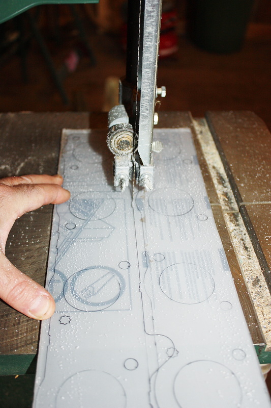
After transferring the dimensions, I used my band saw to cut out the two plastic flanges from the Lexan:
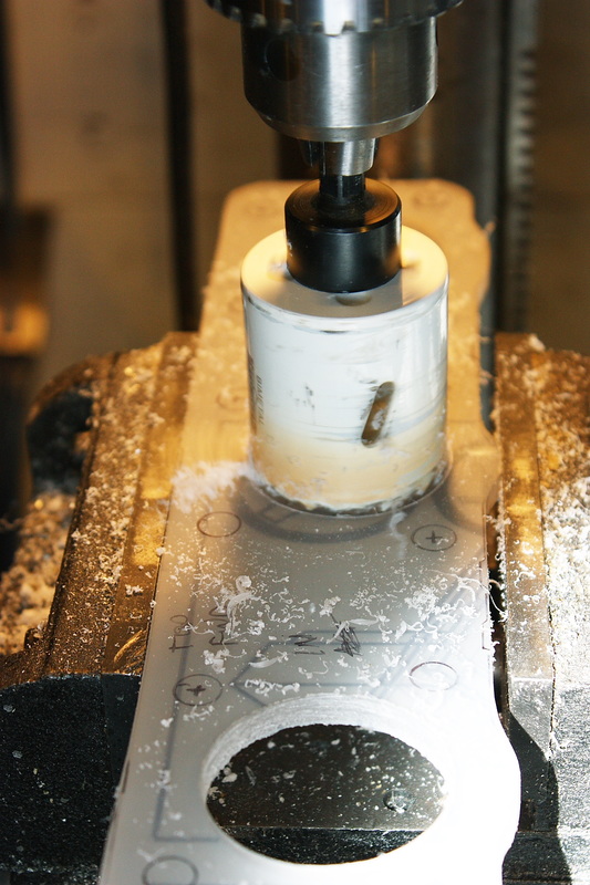
A hole saw in the drill press made easy work of the exhaust ports. Lexan is far more forgiving than Plexiglas for this type of thing since it doesn't crack and chip:
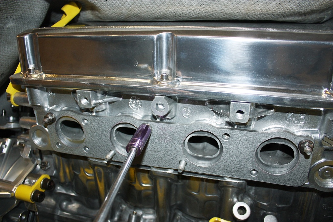
And finally, after a quick coat of paint to make them more visible for the camera, I installed the fake header flanges onto the heads:
Then came the fun of playing plumber again!

 RSS Feed
