It seemed with the headers all mapped out in ABS plastic, and all the steel tubes on hand, it would be a cinch to whip up some headers in a day or so. It was a nice dream while it lasted!
I spent a fair bit of time figuring out how to reliably mark and cut the 180 degree tubes to get the various arcs I needed throughout the system. It seemed a no-brainer until I actually had the pieces laid out in front of me and was ready to go. But there's only one way to ensure that a cut made midway around a bend radius will end up with a perfectly circular opening. And the cut end needs to be perfectly circular to maintain a smooth, constant cross sectional area at the joints.
The trick is to map out the 180 degree bend radius and draw lines radially outward from the centre. I used a piece of paper with guide lines to centre the tube on a radial grid with divisions every 22.5 degrees around a 180 degree arc since my ABS mock-up was made entirely with bends in increments of 22.5 degrees:
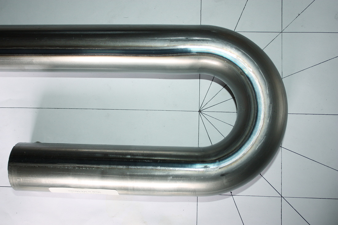
This made it much easier to know where to cut the tubes to replicate the mocked up system.
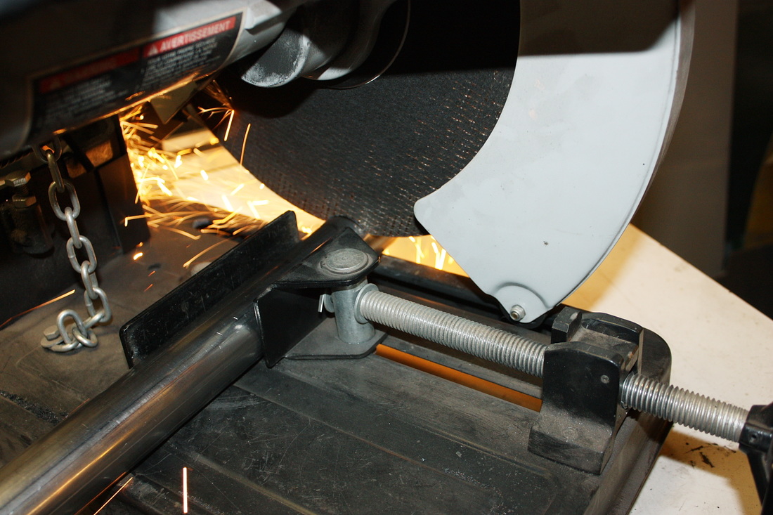
The next challenge was to find a way to cut the tubes accurately around the bends. The blade in my 12" chop saw was way too thick at 1/8", plus whatever run out in the blade. Even if the clamping device could've been oriented to cut the bends (which it couldn't), the kerf would've ruined the leftover pieces by taking too much material off.
A hacksaw was out of the question due to accuracy; a 1/16" cut-off wheel in the angle grinder was out because there was simply no way to stabilize the tilt by hand; and a standard one-wheel manual pipe cutter couldn't be used except to cut the 180 degree bends exactly square at 90 degrees. To cut any other angle, the handle would be tilted off centre and would hit one of the pipe legs before being able to go completely around.
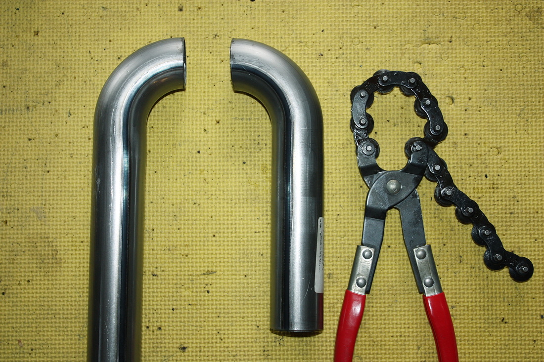
Then I came across the perfect tool:
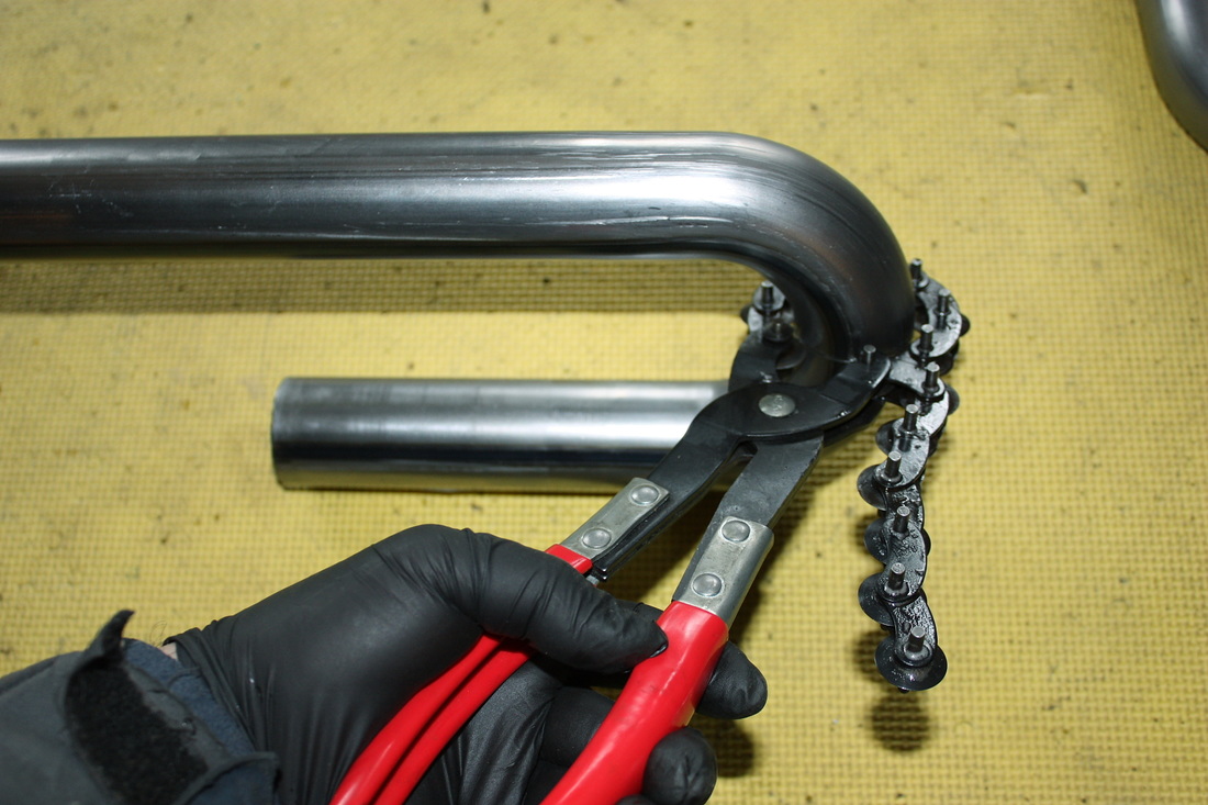
Multiple cutting wheels meant I didn't need to go all the way around the pipe with the handle, yet ensured complete 360 degree cutting. Also, the cutting wheels don't remove any material, making both pieces as accurate as the other.
I still used my chop saw for the long straight cuts. No matter which method I used, I still needed to dress the cut ends with a file to remove burrs and flash from the inside diameters.
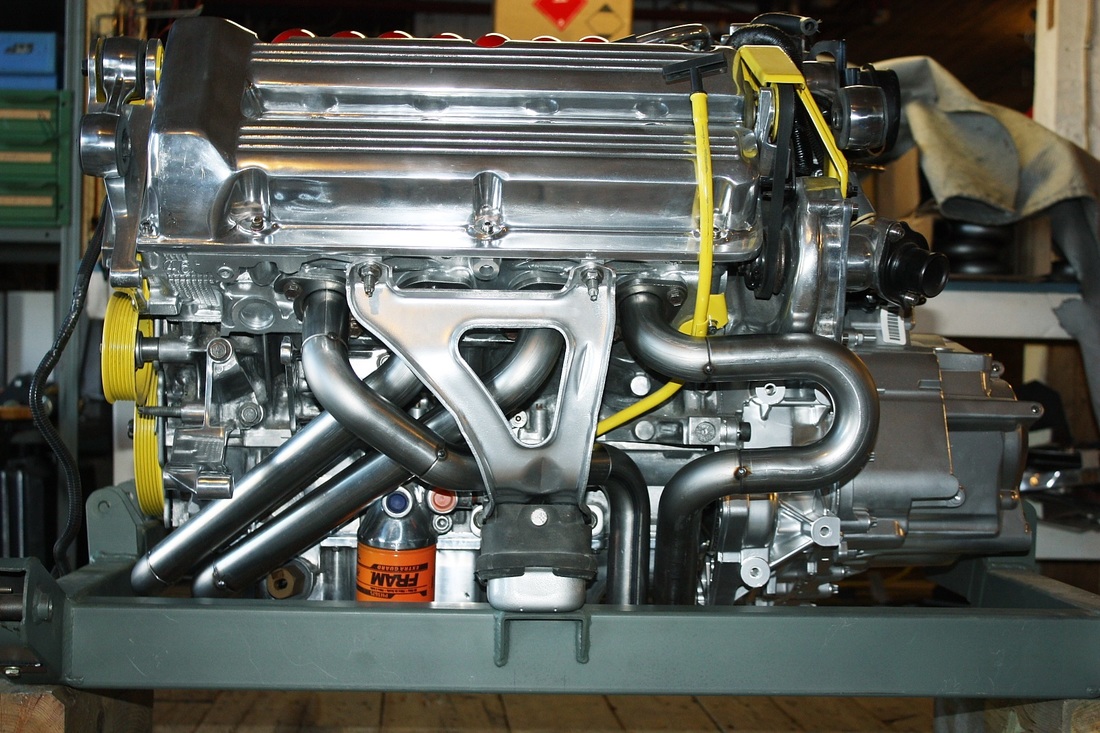
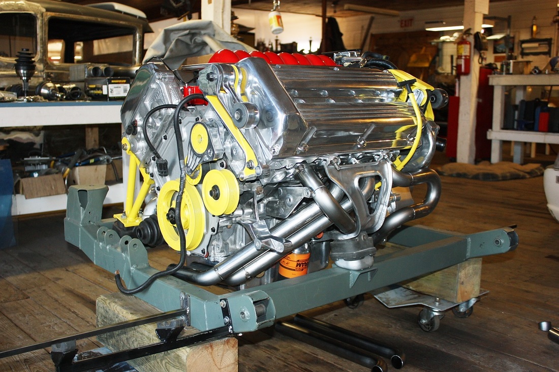
I obviously won't go through the build up of each primary pipe, but I will show a few details that complicated and slowed things down. Here's a photo showing three of the four primaries tacked in place on the forward cylinder head:
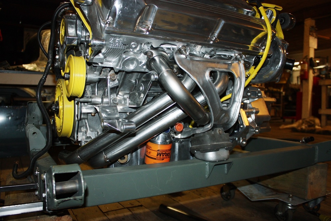
My primary concern when I was building the plastic mock up system was simply to get the pipes the same length, and get them to fit... anywhere. I had to change my focus to maintenance and clearance issues when finalizing the steel system. For example, I had to juggle the angles of the pipes for cylinders #4 and #6 within a tight window to allow access to oil cooler fittings and the oil level sensor, and an alternator bracket:
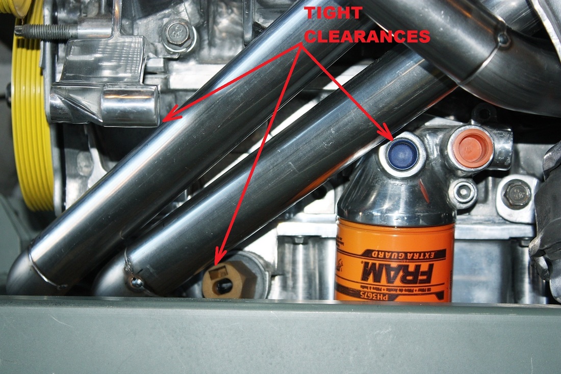
As it stands, the alternator retaining bolt that threads through the bracket in the photo above will have to be replaced by a locating pin to allow removing the alternator without having to remove the header. There are three other alternator retaining bolts so I'm not concerned about the alternator coming loose.
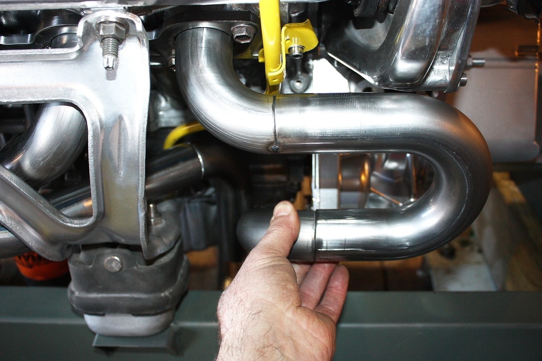
This next photo shows the tight corridor the pipe from cylinder #2 must thread between the engine mounting bracket and the pipes from cylinders 4 and 6; the engine mounting stud; and the dipstick tube. Luckily, the dipstick made a little dog leg bend in just the right spot as if it were made for it!
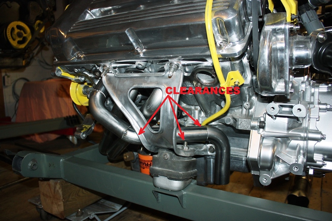
Notice in the photo above that the last exhaust port (#8) still doesn't have it's primary pipe. I'll walk through the fabrication of that pipe since it was quick and easy.
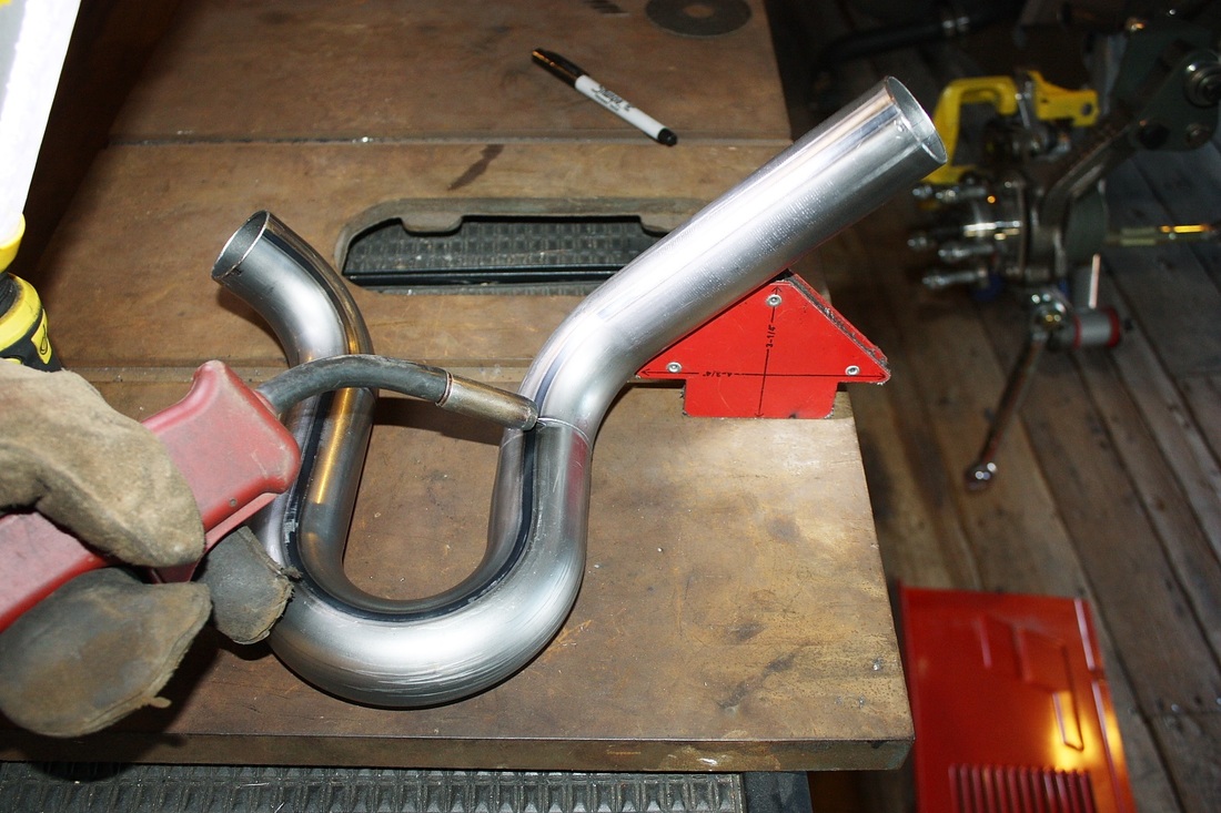
Since pipe #8 had to be the same length as #2, I re-measured the as-installed length of #2 and made a few adjustments to the overall dimensions for #8. Then, I cut up one bend at 90 degrees to exit the cylinder head, and left another at 180 degrees, and tacked them together after setting them at a 45 degree angle to each other:
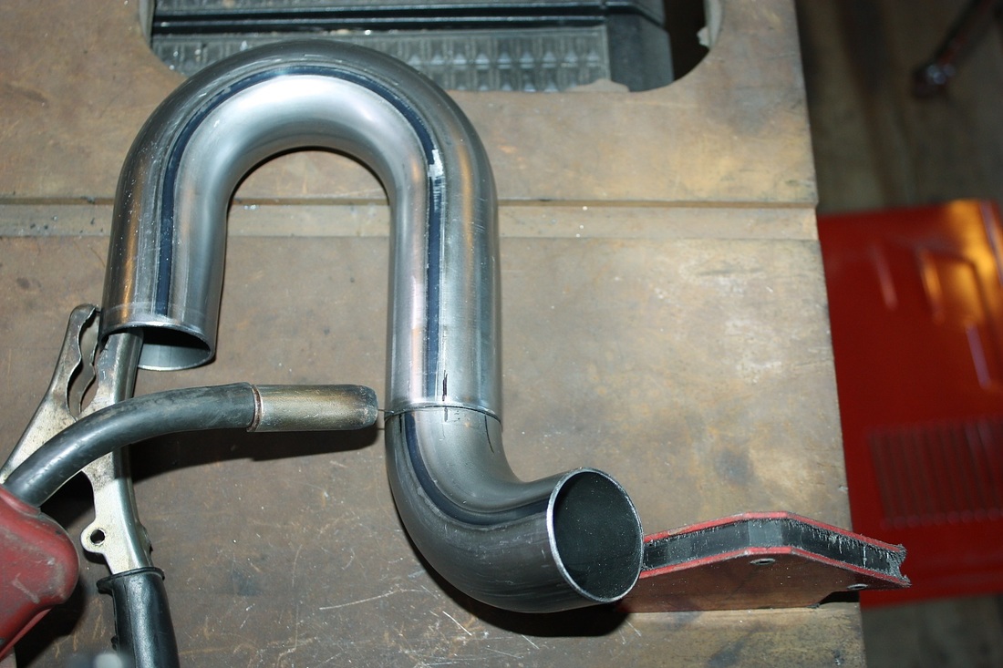
The looping around is simply to make up the extra length needed to match the overall length of the tube from cylinder #2.
A third section of pipe with a 90 degree bend was then added to the first two. Final welding will be TIG'ed if I can afford to pay someone, or MIG'ed by me but only after I've had plenty of practice with the leftover bits of pipe:
The tacked up section was then test fitted in place:
Stepping back, here's how all four primary pipes for the forward cylinder head looked:
I hadn't added the final sections leading under the transmission and engine to the collectors on any of them yet, because I wanted to develop the primary pipes on the aft cylinder head next, and fine tune the end point of all eight pipes at once.
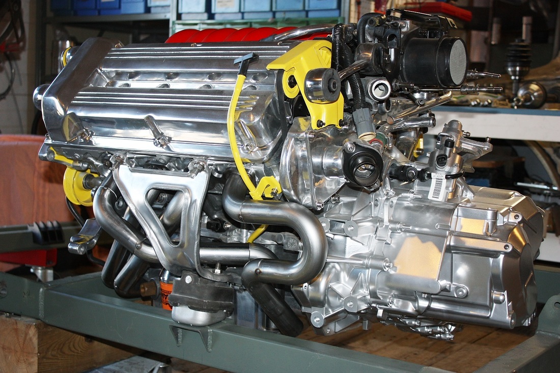
Here's the full face view of the even numbered primary pipes:
And lastly, here's the view from the front quarter. The alternator was removed to get #2 cylinder pipe in place. Removing the header in the future will require supporting the engine and removing the forward engine mount and bracket seen in this photo:
I hope to be able to remove the two headers and collectors as one piece when all is said and done. We'll see soon enough!

 RSS Feed
