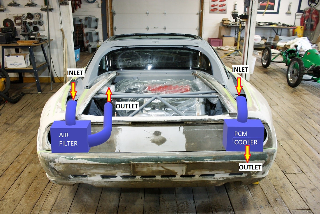
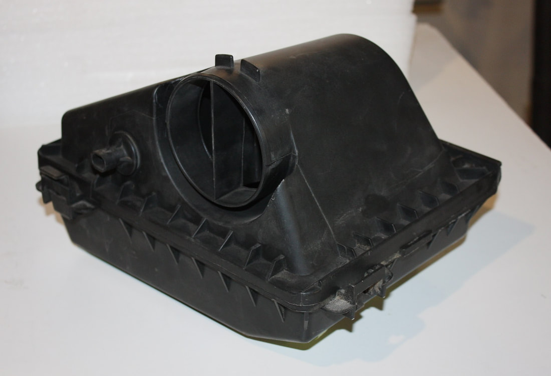
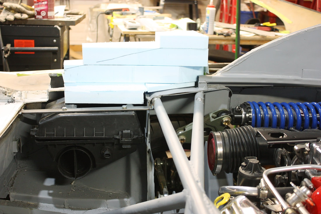
In my last post, I built the basic air box to mount the PCM in the engine bay along with the air scoop to feed the box with fresh air from the quarter window area. This post is about how I mounted the PCM inside the box, directed the airflow through the box, and protected everything from the heat of the nearby exhaust system.
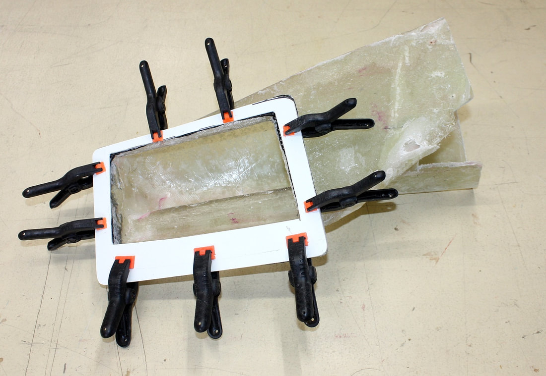
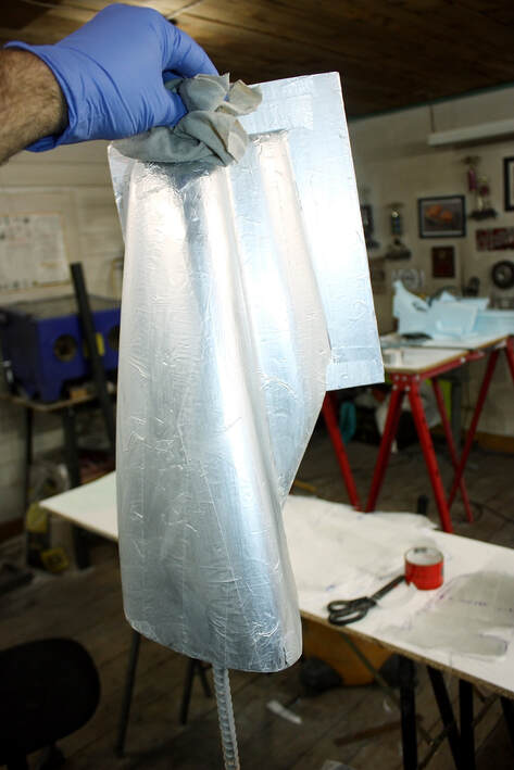
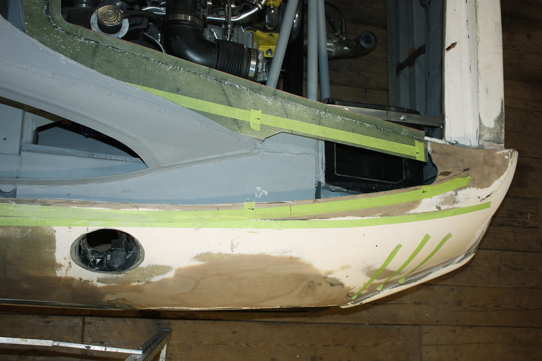
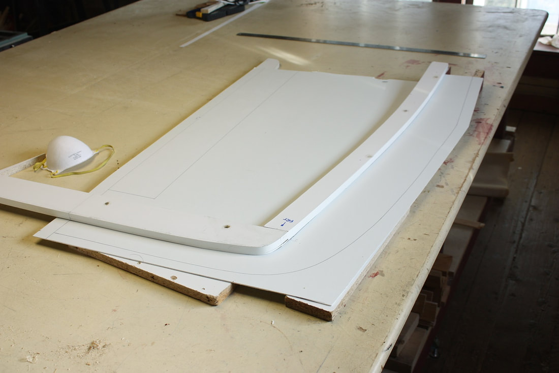
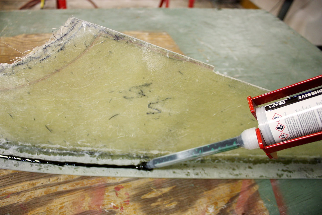
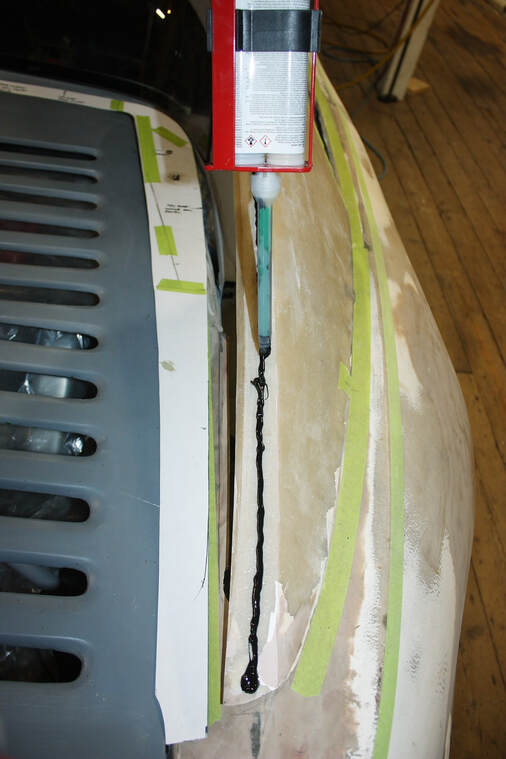
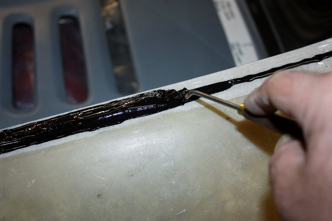
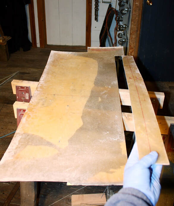
For starters, I needed to make a tighter seal between the air box and the fibreglass scoop since the male molds I used to make them left the mating surfaces somewhat uneven. I bought a flat 4’ x 8’ x 1/8” sheet of fibreglass reinforced plastic (FRP) that’s normally used in making shower stall walls from the local hardware store. It was a handy and very cheap way to get some flat fibreglass-compatible stock for making nice smooth surfaces quickly. I traced the mating surfaces of the air box and the scoop onto the FRP, cut them out, and epoxied them directly to my fibreglass forms:
While the epoxy set up, I pulled out my drawing pad and started planning how to manage the airflow through the box. My conundrum was that both the inflow and outflow would have to be routed through the top of the box since it’s surrounded by the sheet metal chassis on four of its six sides. One free side had to be left clear for an access door, so that left the top of the box as the only surface.
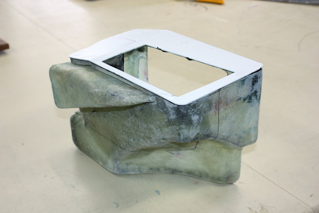
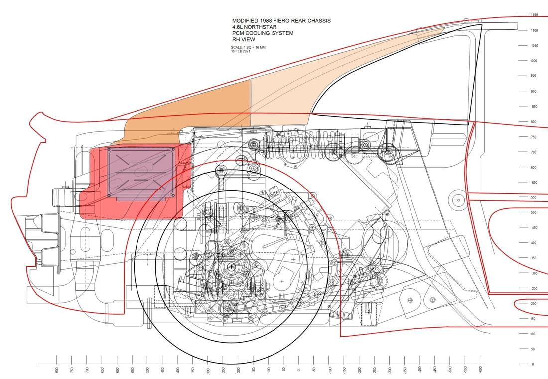
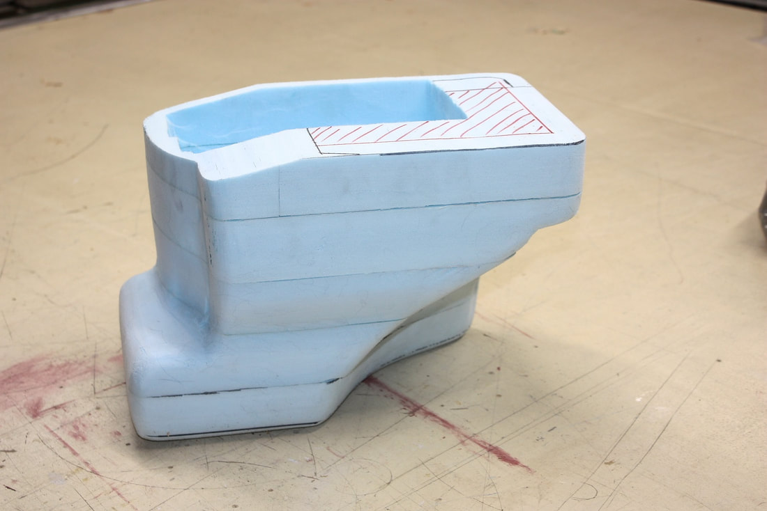
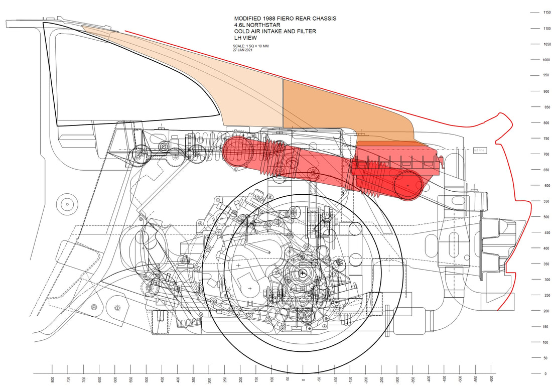
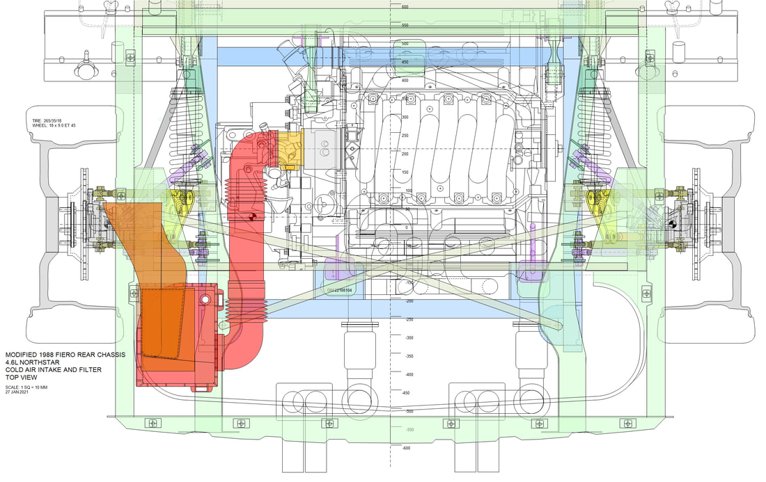
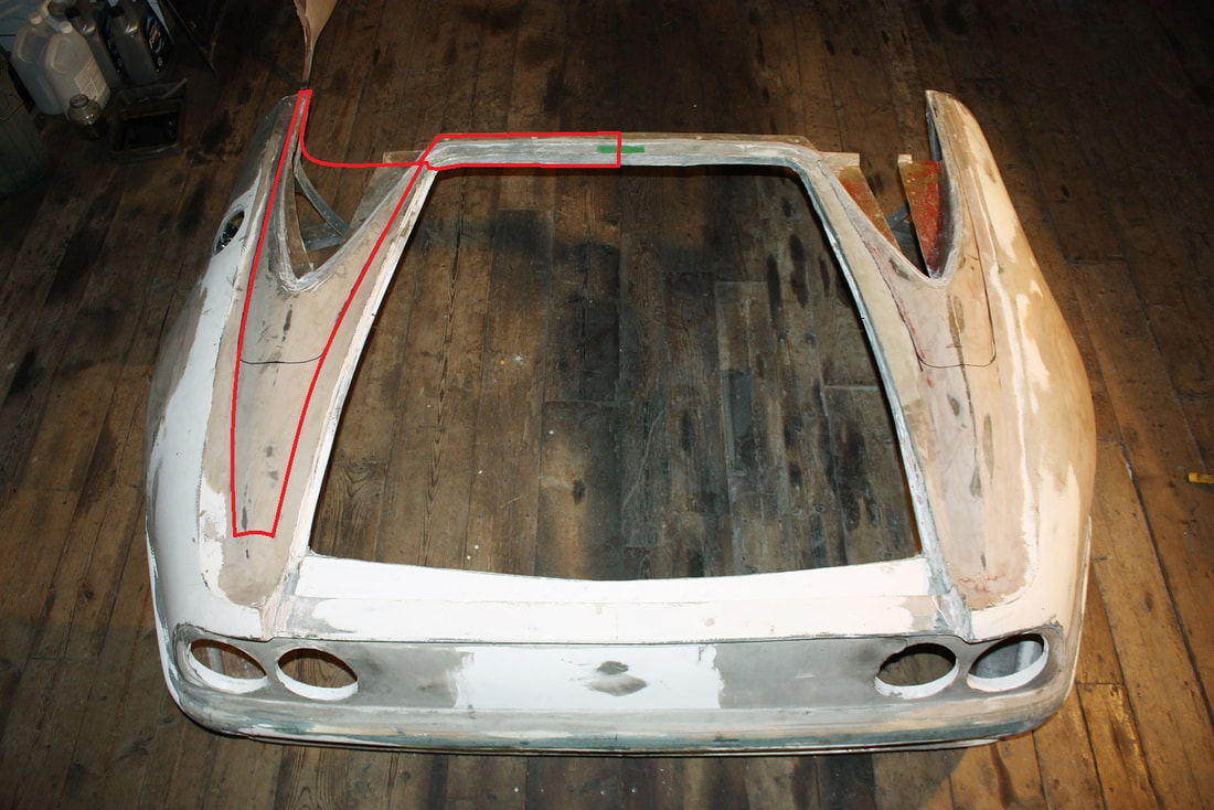
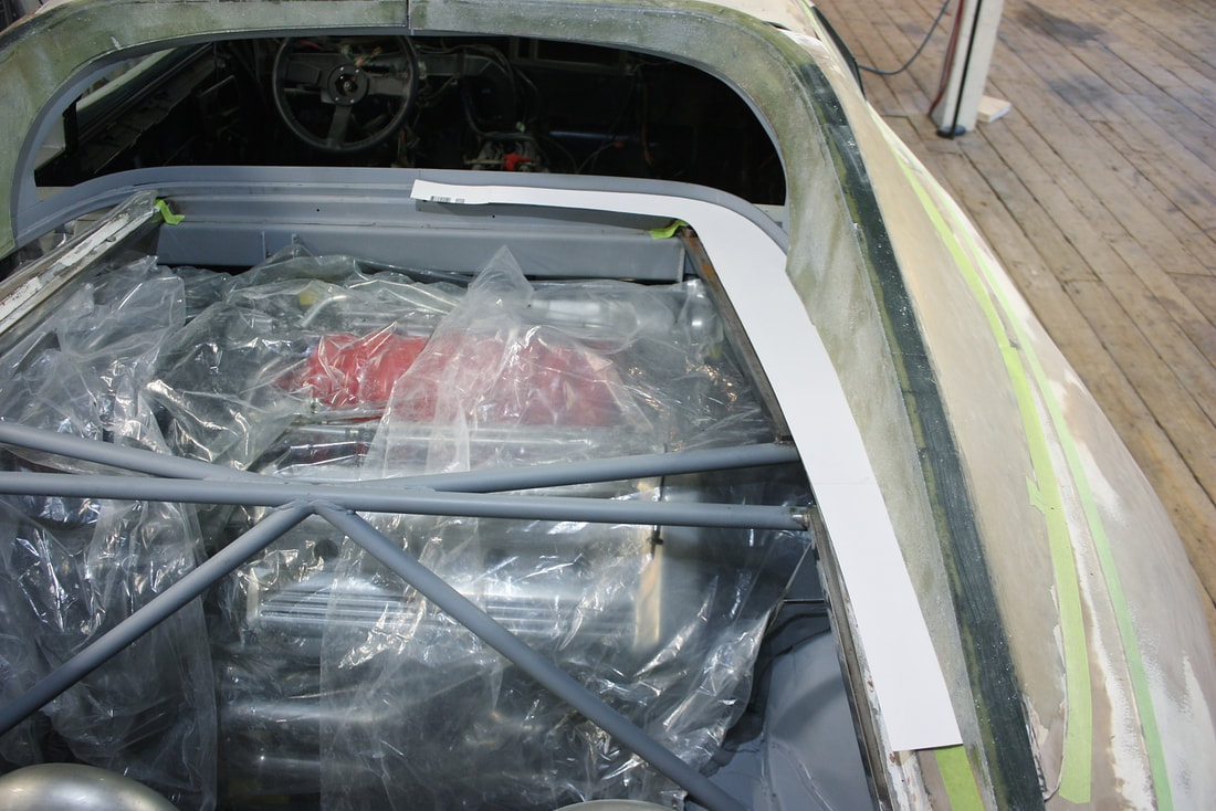
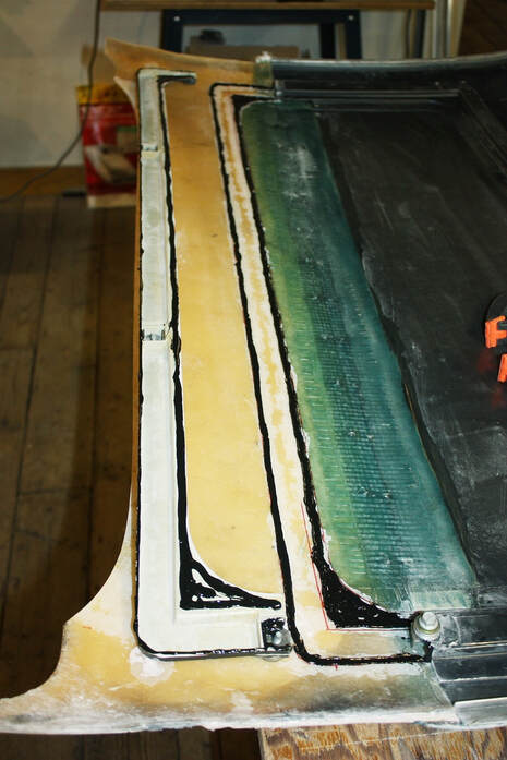
That is until I realized I could exhaust the box through the triangular shaped hole I’d cut out of the metal trunk sidewall in my last post. The final concept started coming together nicely after that. The key to forcing all the incoming air over the PCM was to divide the air box into a left and right chamber using a wall (see red part below) with a gap at the bottom. The PCM and air inlet would be on one side of the wall, while the exhaust port would be on the other like so:
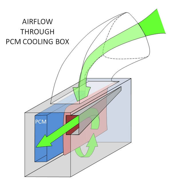
Conveniently, the exhaust port would join the airstream flowing rearward over the wheel well liner coming from the radiator, and out the mesh-grill tail light panel. Simple and effective.
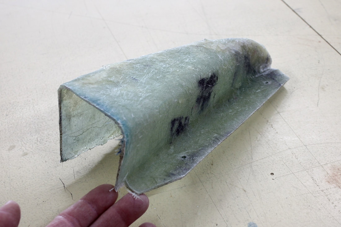
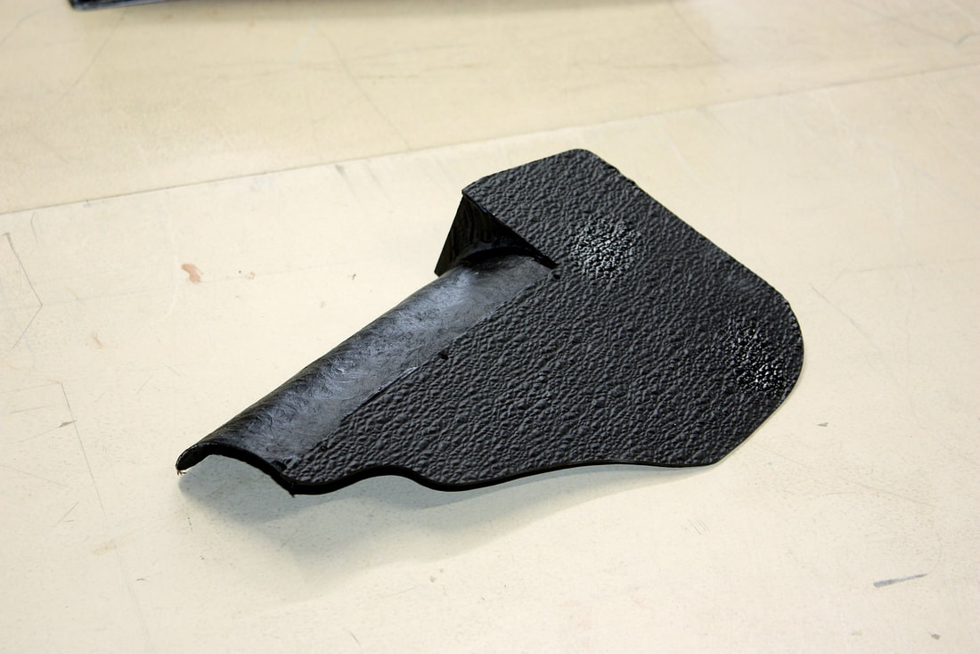
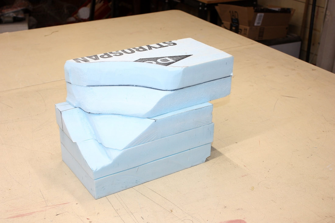
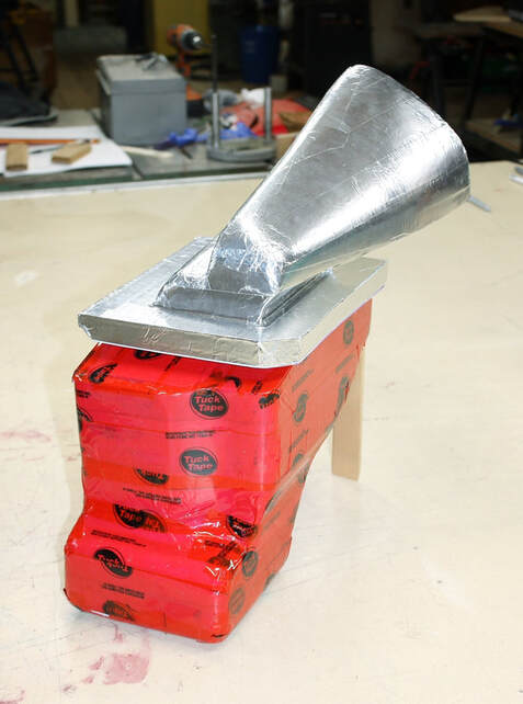
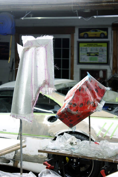
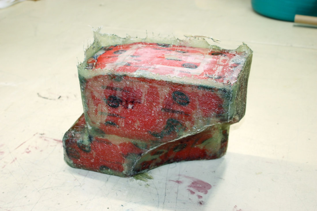
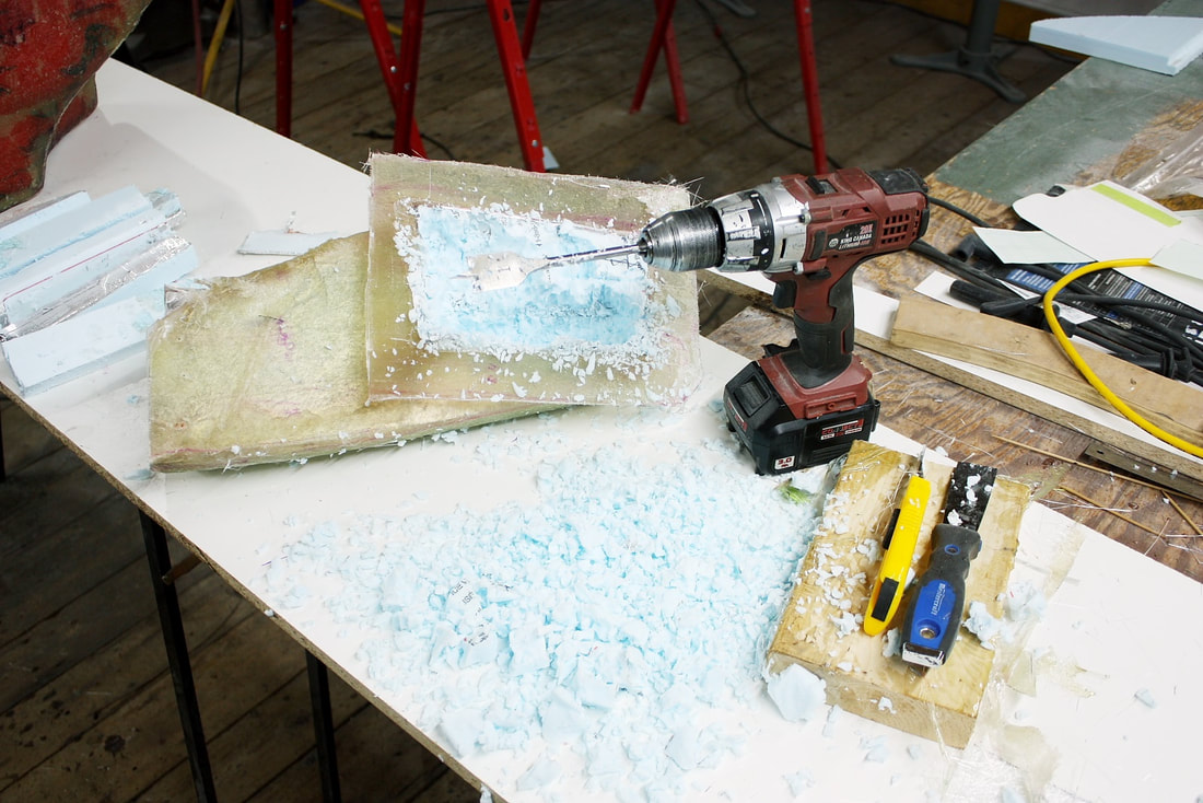
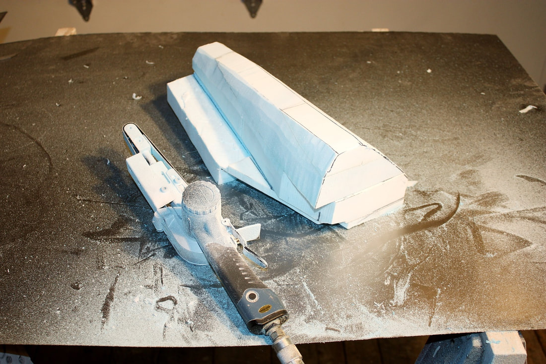
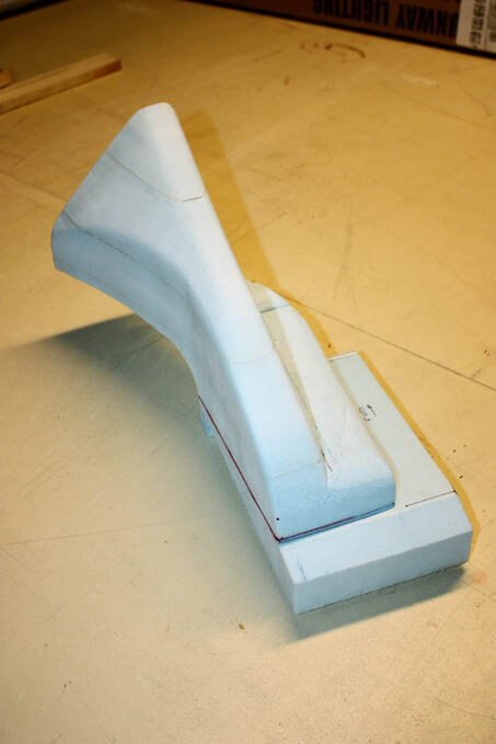
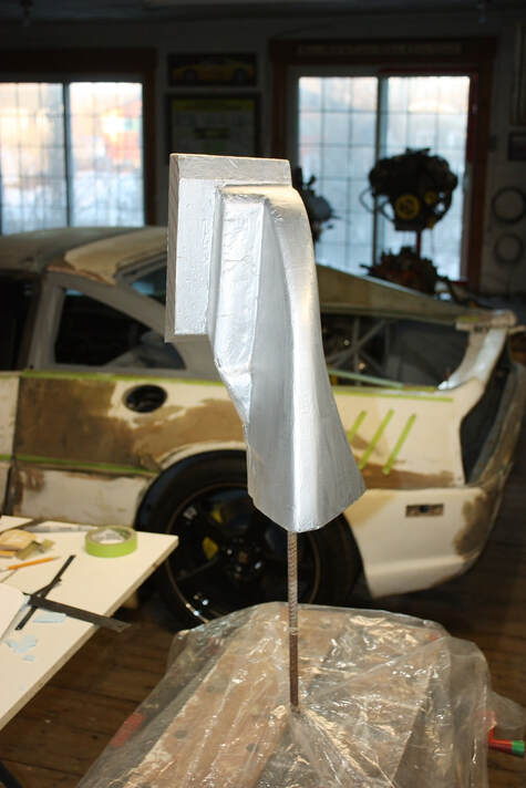
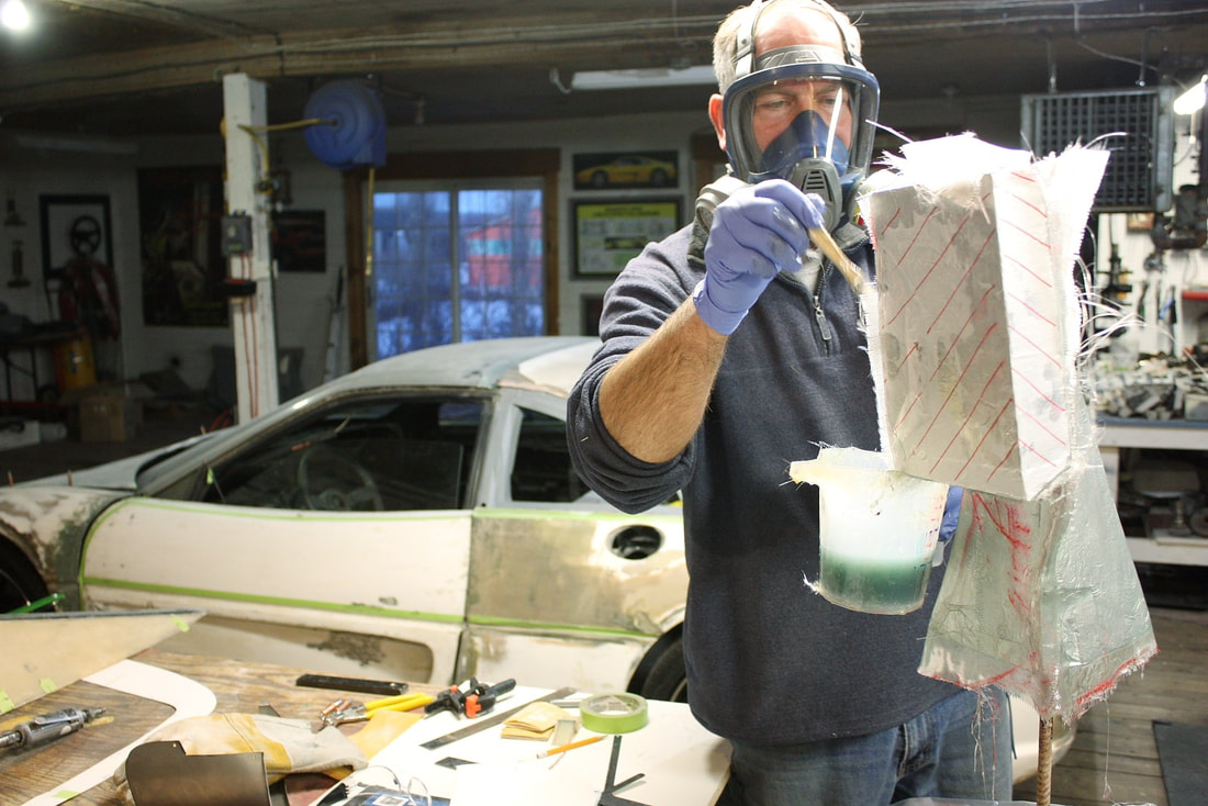
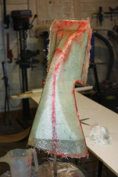
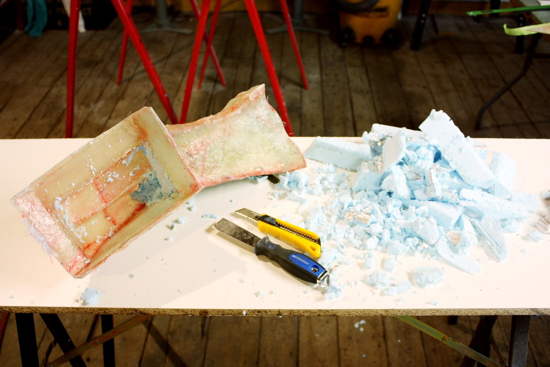
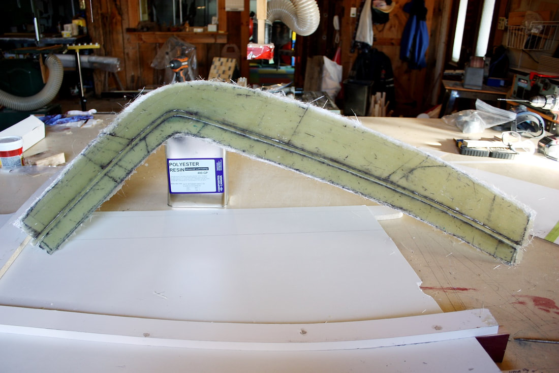
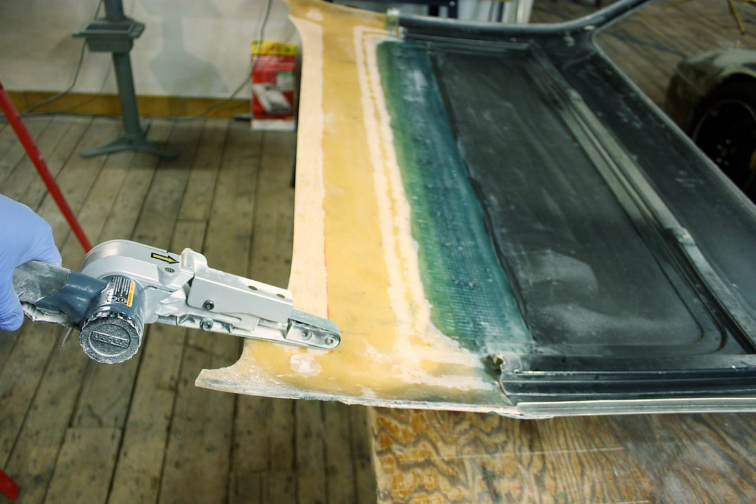
So the first step was to create an exhaust scoop for the air box. I glued several pieces of Styrofoam together, shaped them with my pneumatic belt sander, then cast a fibreglass shell of the part:
Conveniently, the exhaust port would join the airstream flowing rearward over the wheel well liner coming from the radiator, and out the mesh-grill tail light panel. Simple and effective.
So the first step was to create an exhaust scoop for the air box. I glued several pieces of Styrofoam together, shaped them with my pneumatic belt sander, then cast a fibreglass shell of the part:
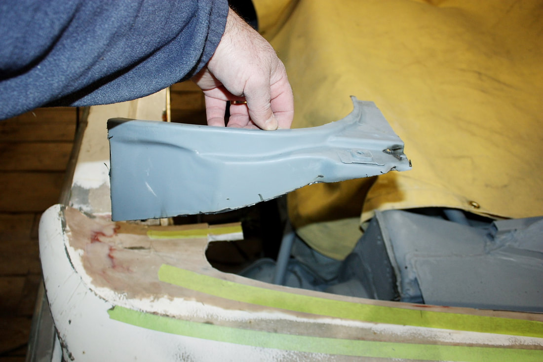
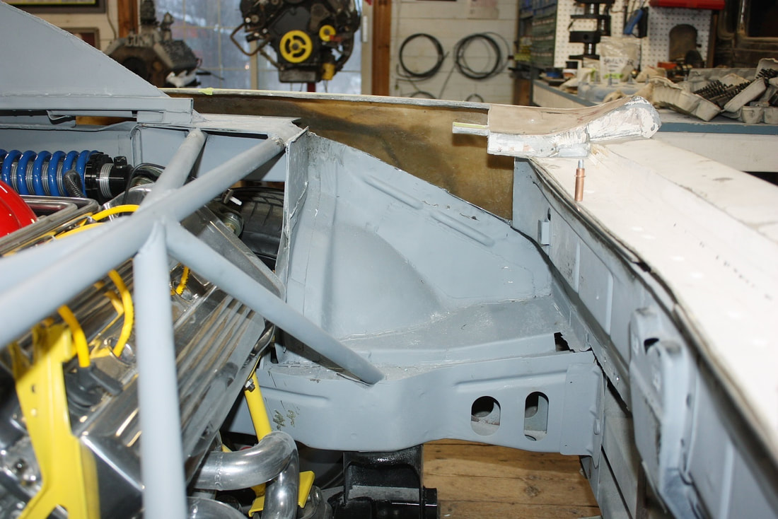
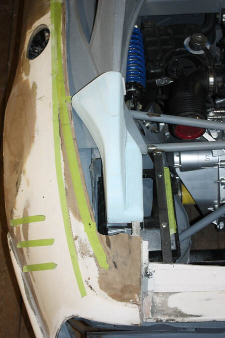
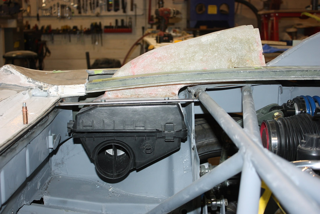
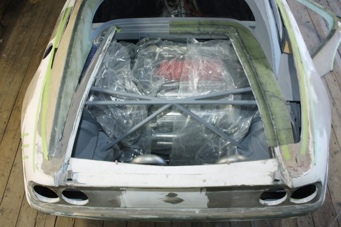
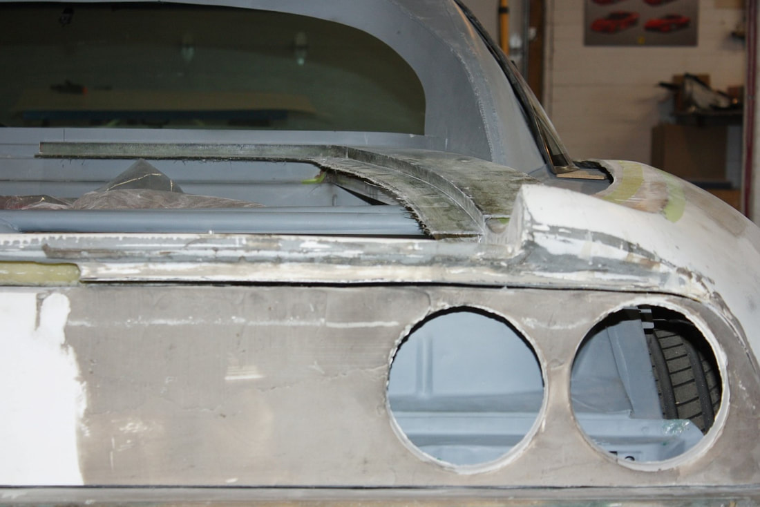
Next, I marked the best location for the port on the air box, cut out the triangular shaped hole, and epoxied the new exhaust scoop to the air box:
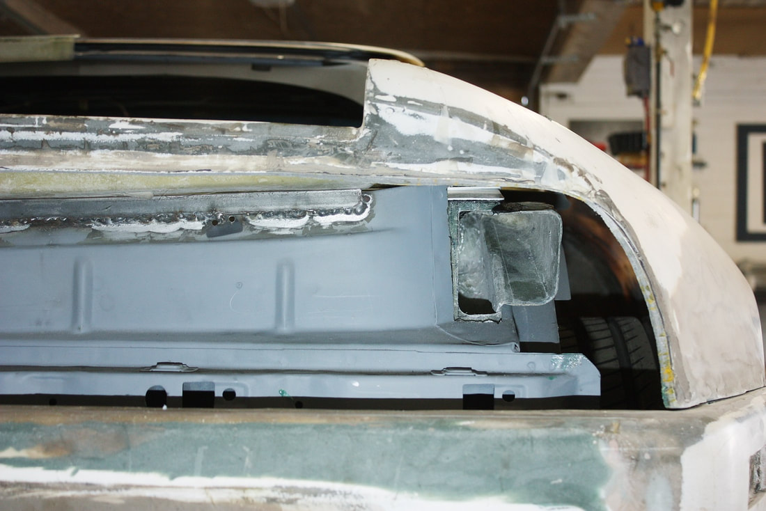
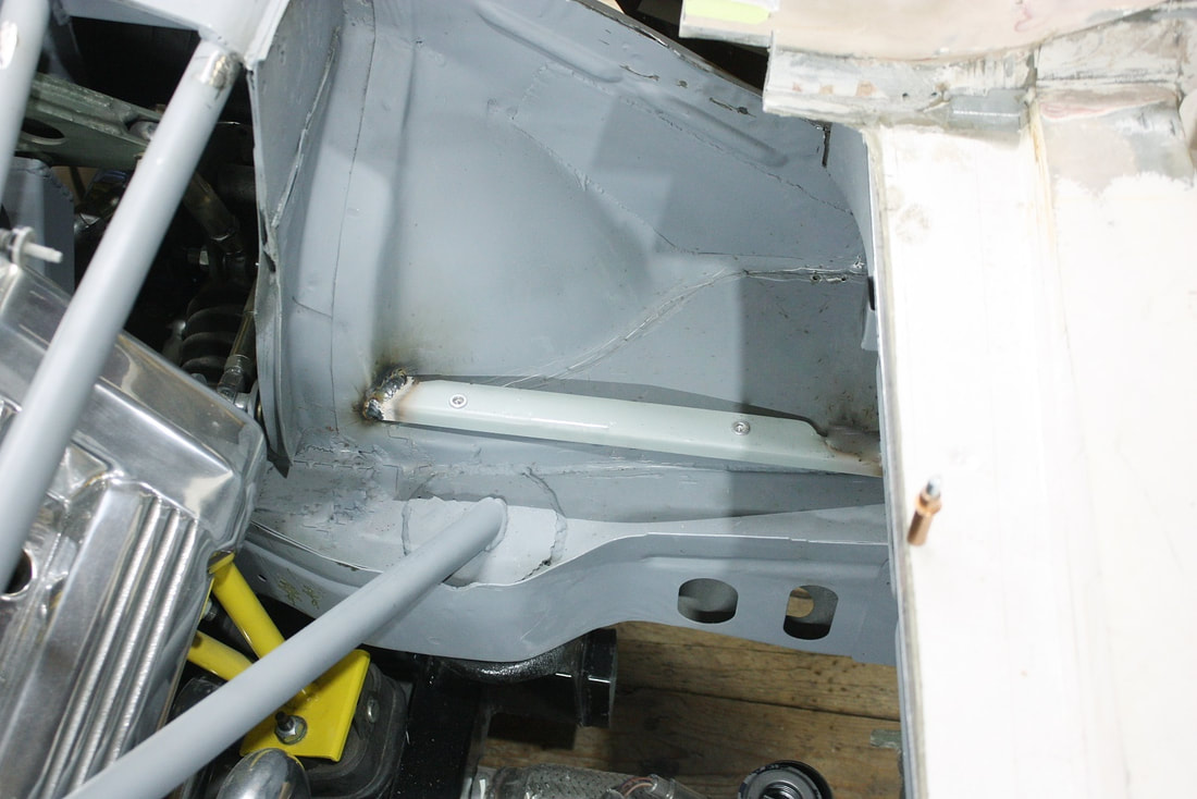
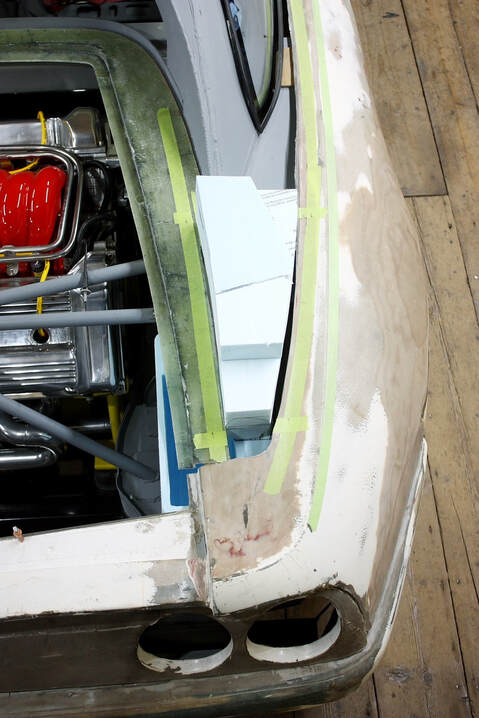
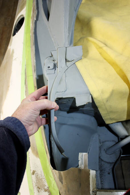
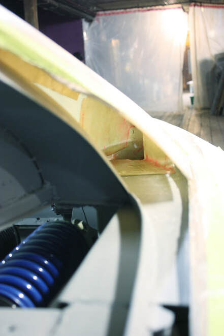
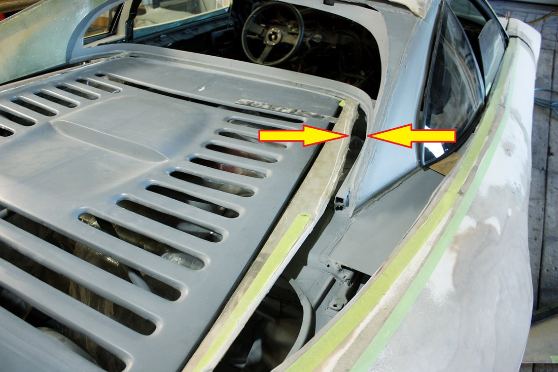
If you found my explanation above confusing, this should clear it up. Note how the exhaust scoop vents into the tunnel above the rear wheel:
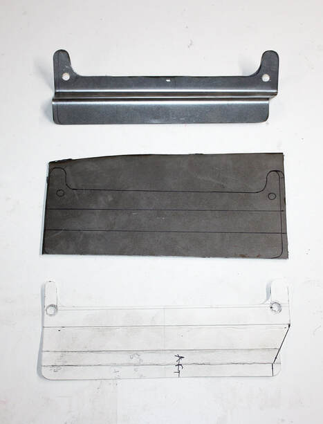
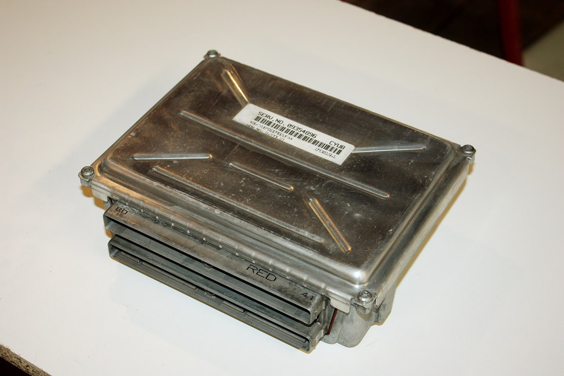
At this point, I had a single chamber with an intake and an exhaust. Next I needed to mount the PCM itself inside the box. I played around with cardboard templates until I found the right combination of height, depth, and lateral placement of the PCM, then cut and formed a pair of steel brackets:
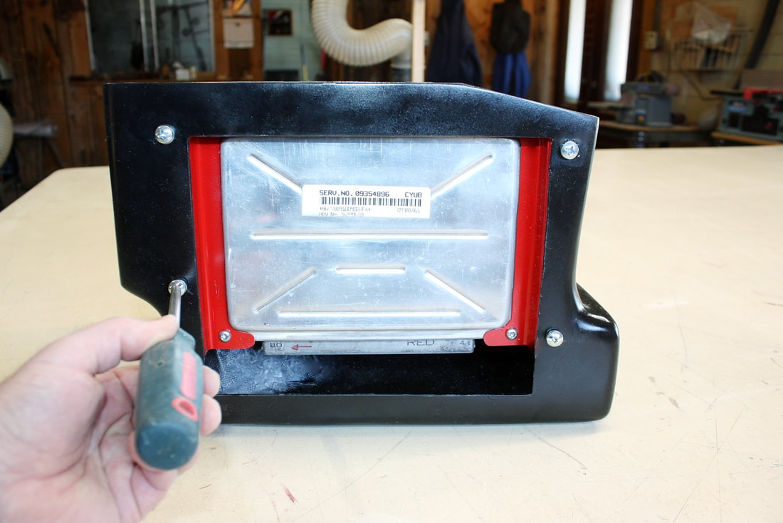
I used the PCM cover plate screws to bolt the brackets to the PCM, and installed some nutserts on the bracket flanges to mount them to the fibreglass air box:
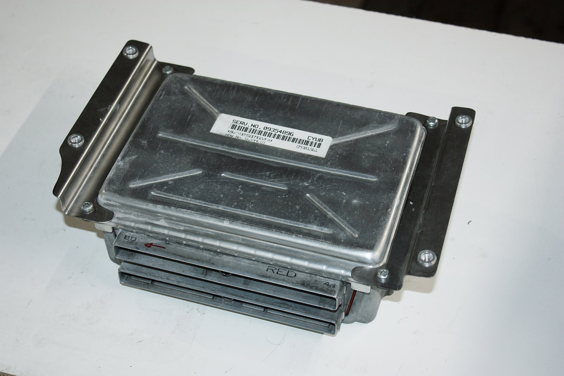
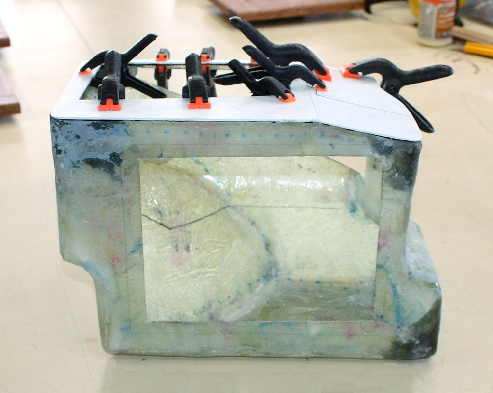
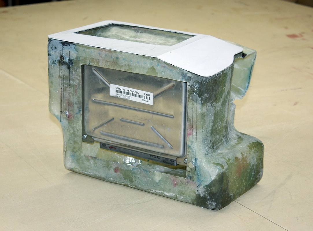
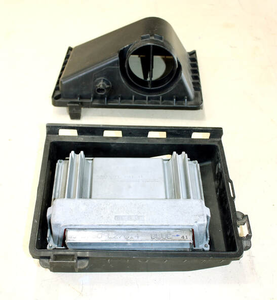
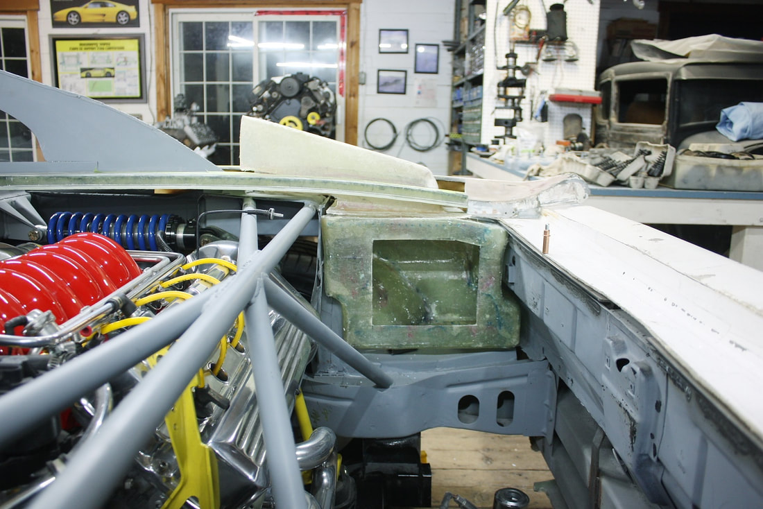
Here’s the PCM mounted neatly inside the air box. Notice I displaced the processor as close to the inside wall of the box as possible to leave room for the second chamber. I also mounted it as high as possible to leave room for the large electrical connectors at the bottom of the PCM:
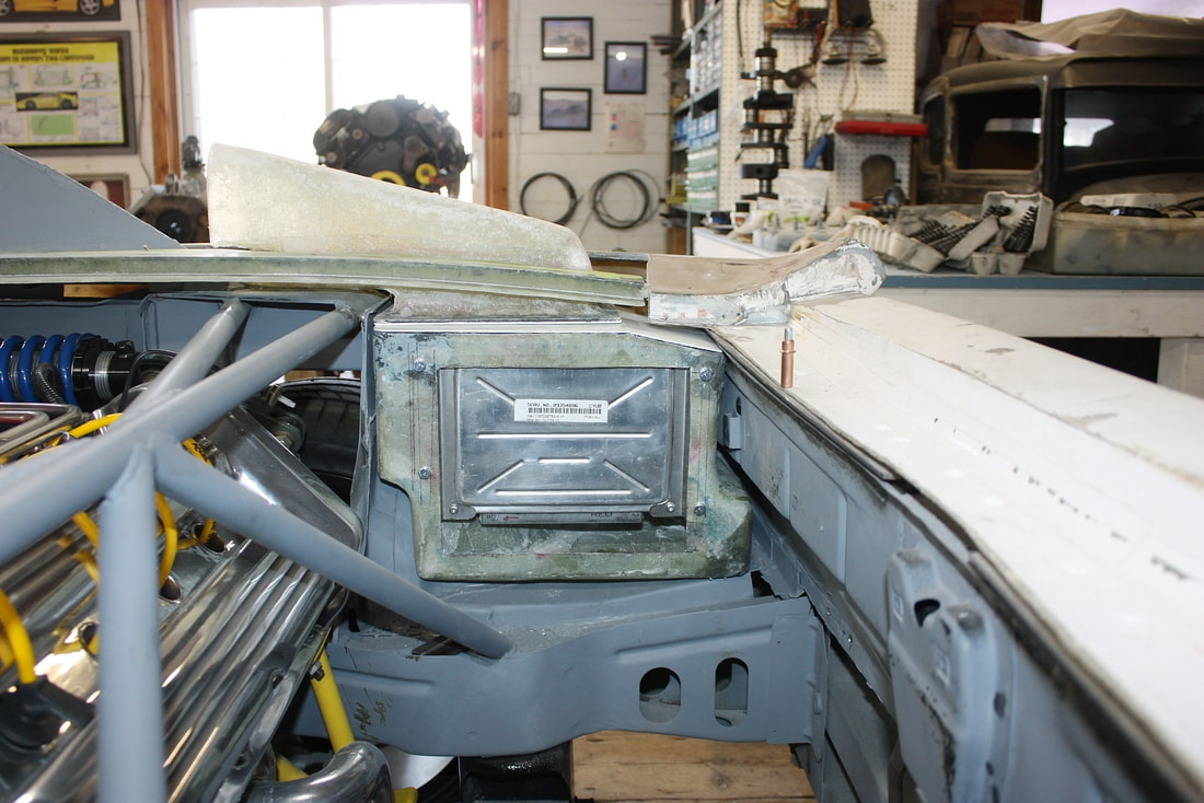
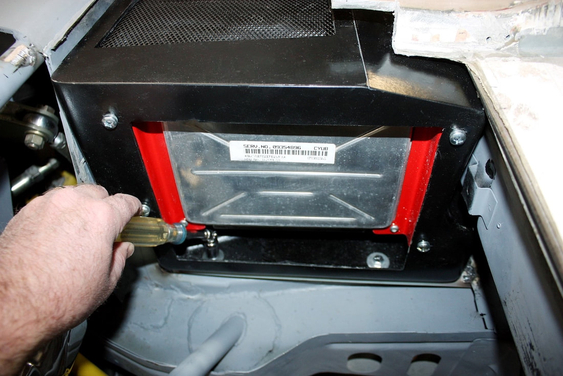
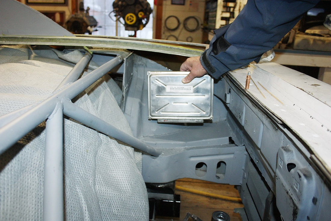
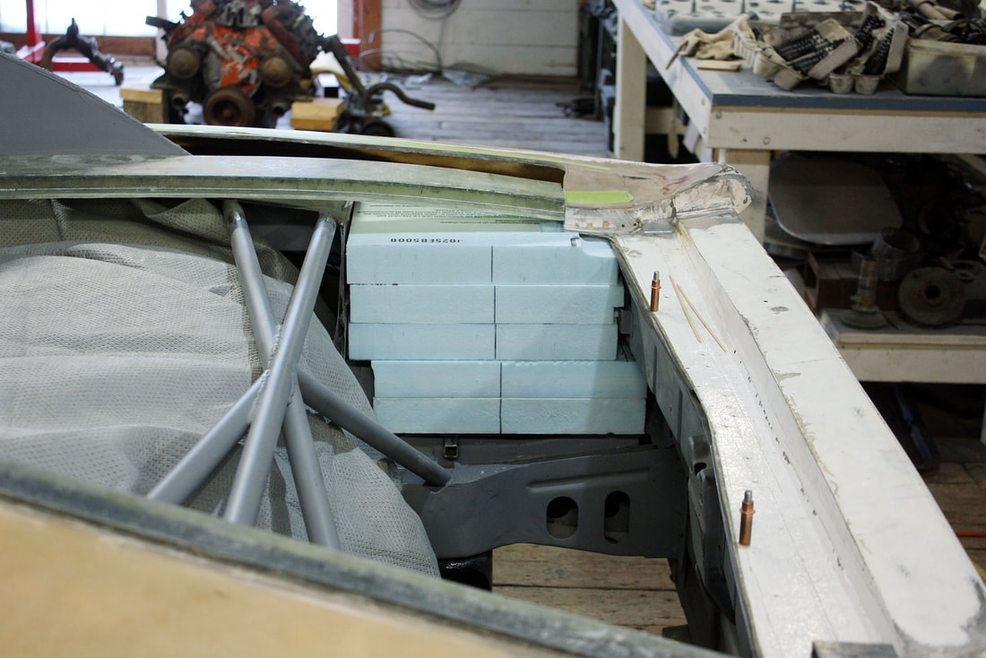
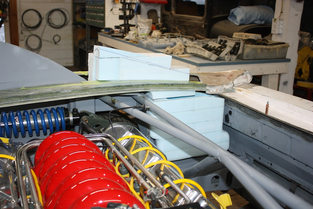
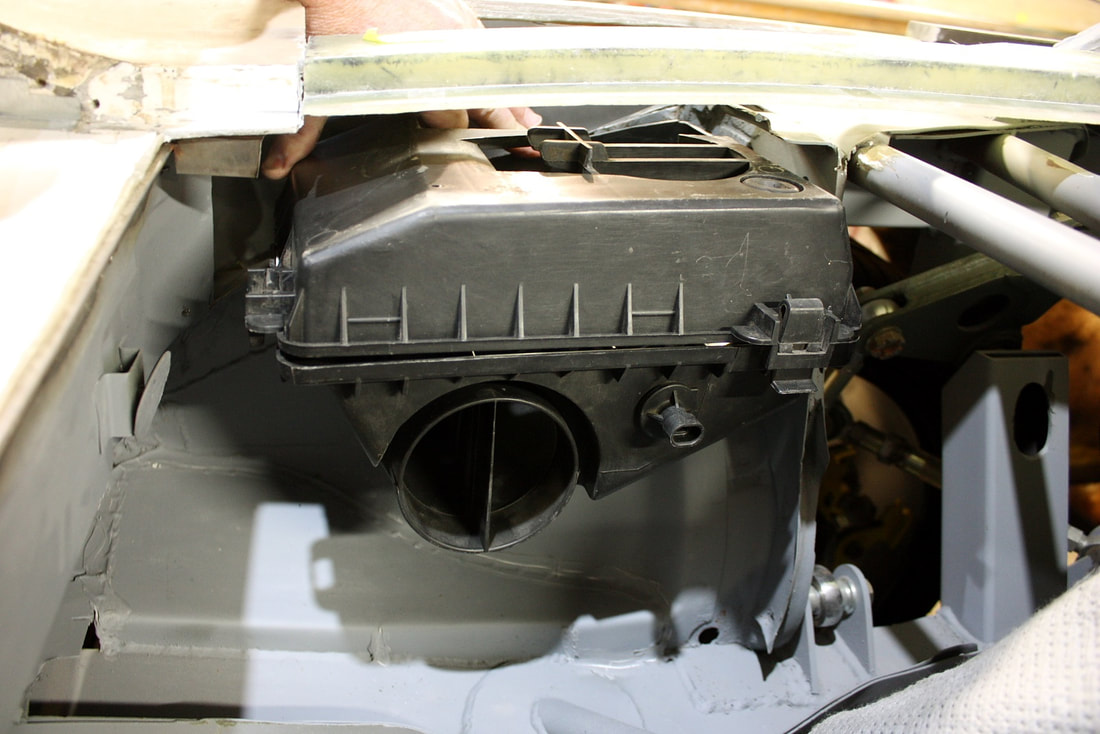
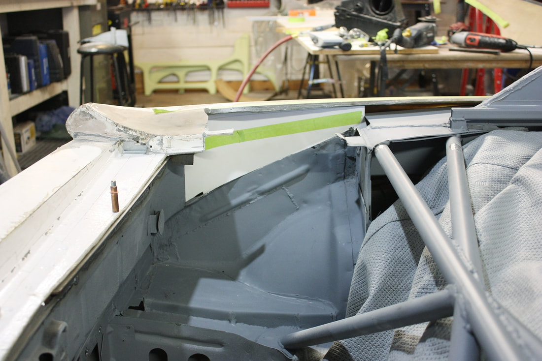
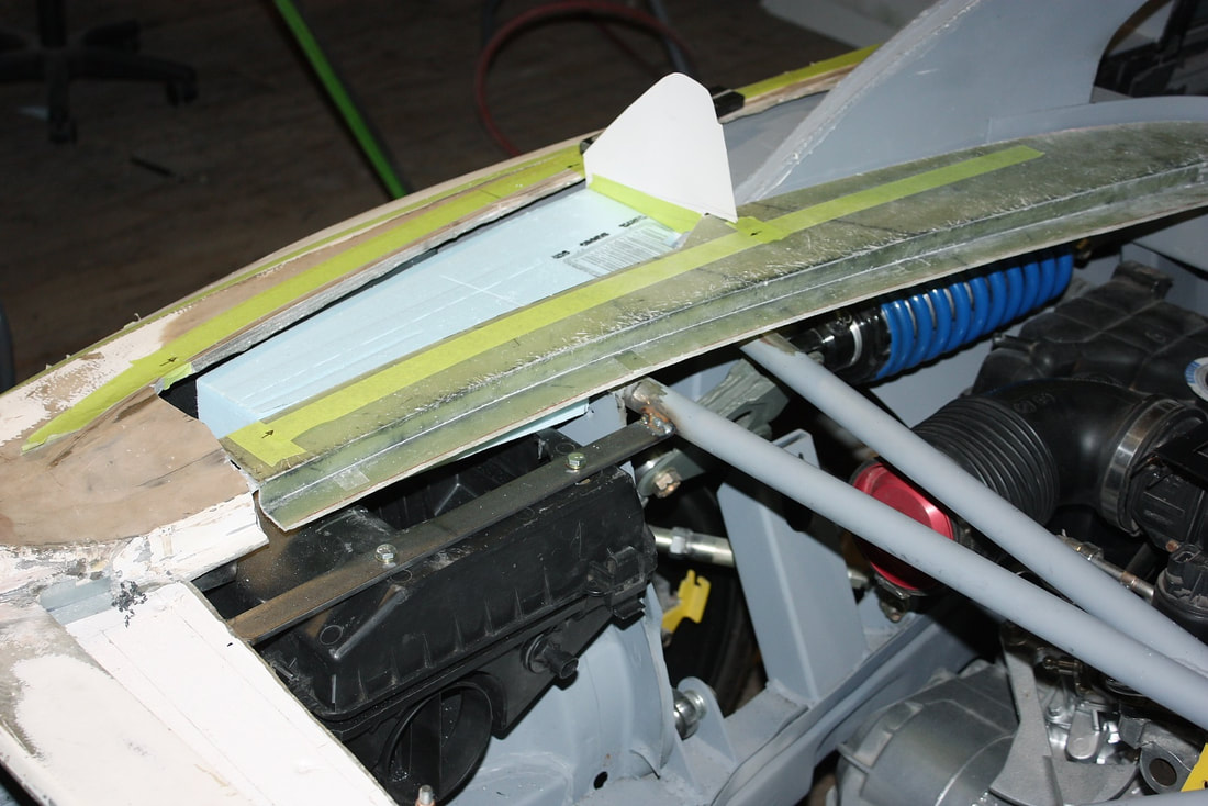
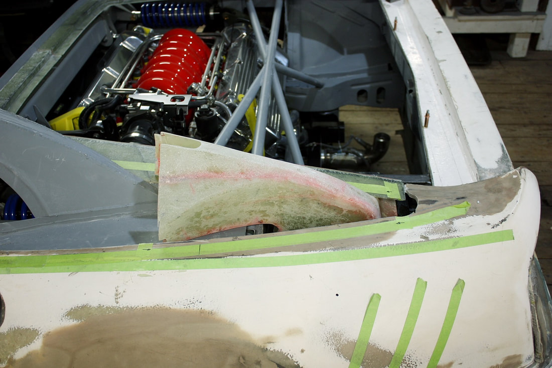
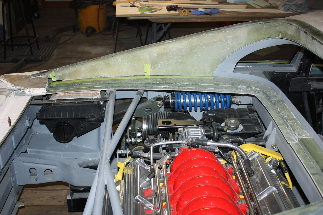
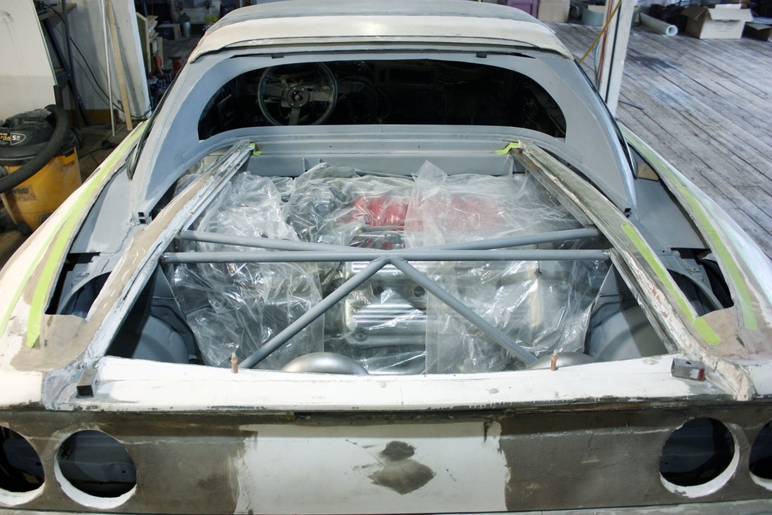
Next, I mocked the assembly up into the chassis to make sure none of the latest changes affected the fitment of the intake scoop, and consequently, the fitment of the sail panel. So far so good:
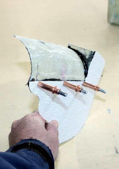
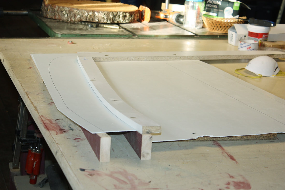
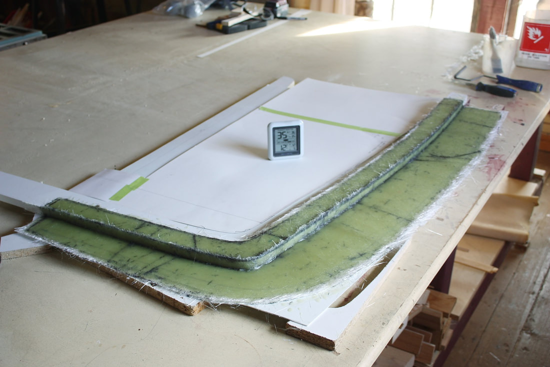
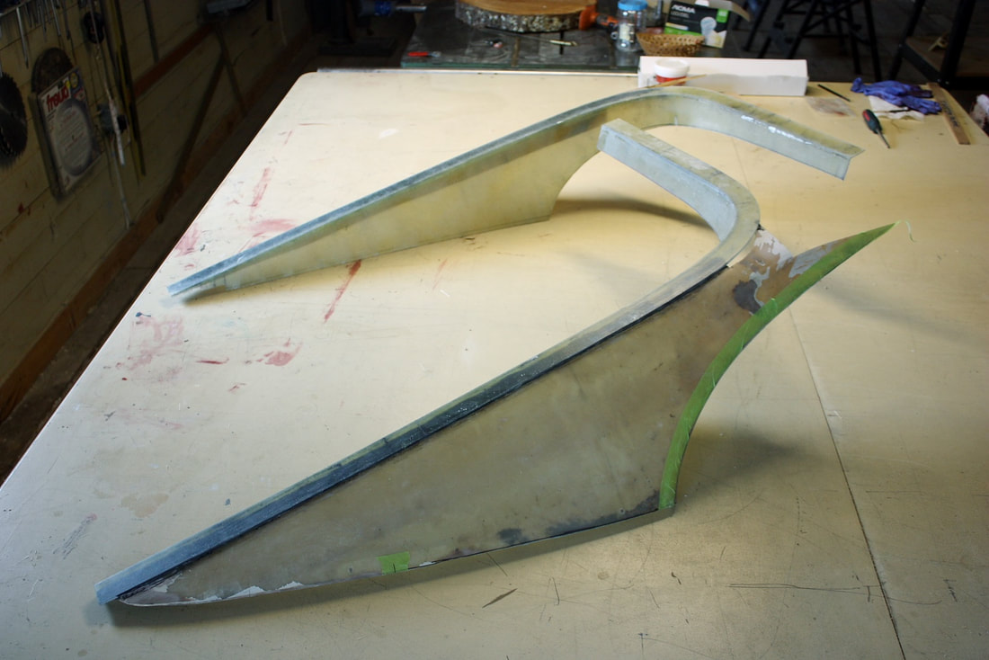
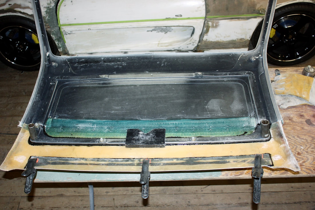
From there I needed to fabricate the interior wall to divide the air box into two separate chambers, connected by an airspace at the bottom. The first problem was that the air inlet hole occupied most of the box top, so I needed to offset the incoming air toward the PCM side of the box. I did that by laying up some fibreglass on a spare section of 4” diameter sewer pipe I had on hand, then once cured, I cut it and epoxied it to an intricately shaped piece of FRP to form the diverter/center wall, like so:
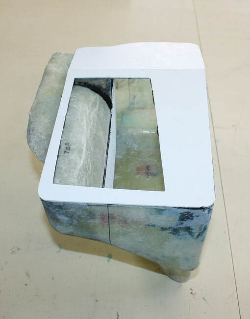
This is what the air diverter and center wall looked like once mocked up inside the box:
Once the diverter wall was properly fitted, I took it out and painted it in preparation for final installation:
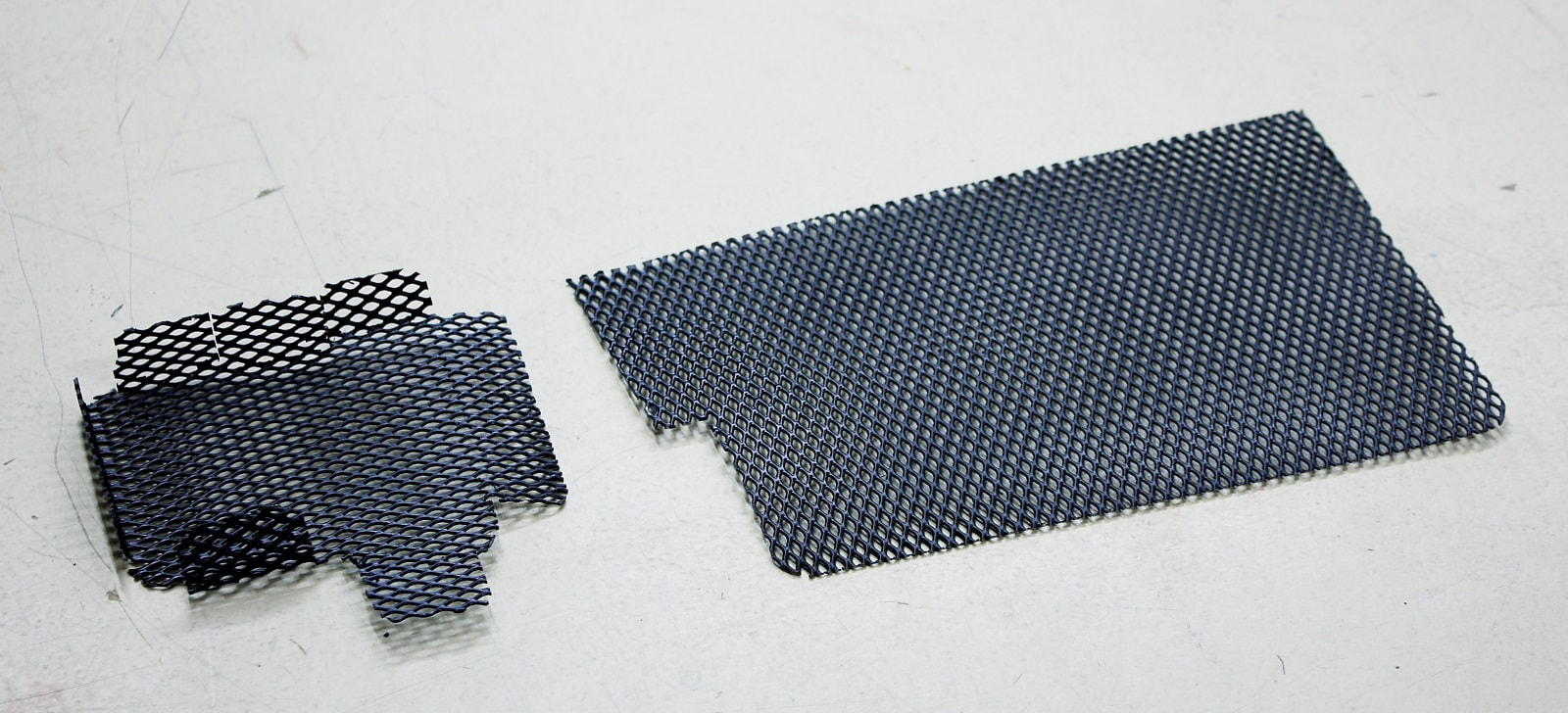
Next up I made a series of parts needed to complete the installation starting with inlet and exhaust screens to keep leaves and vermin out of the cozy little box I’d created. Several years ago a neighbour decommissioned an old 1st generation satellite dish from which I salvaged the aluminium mesh panels…
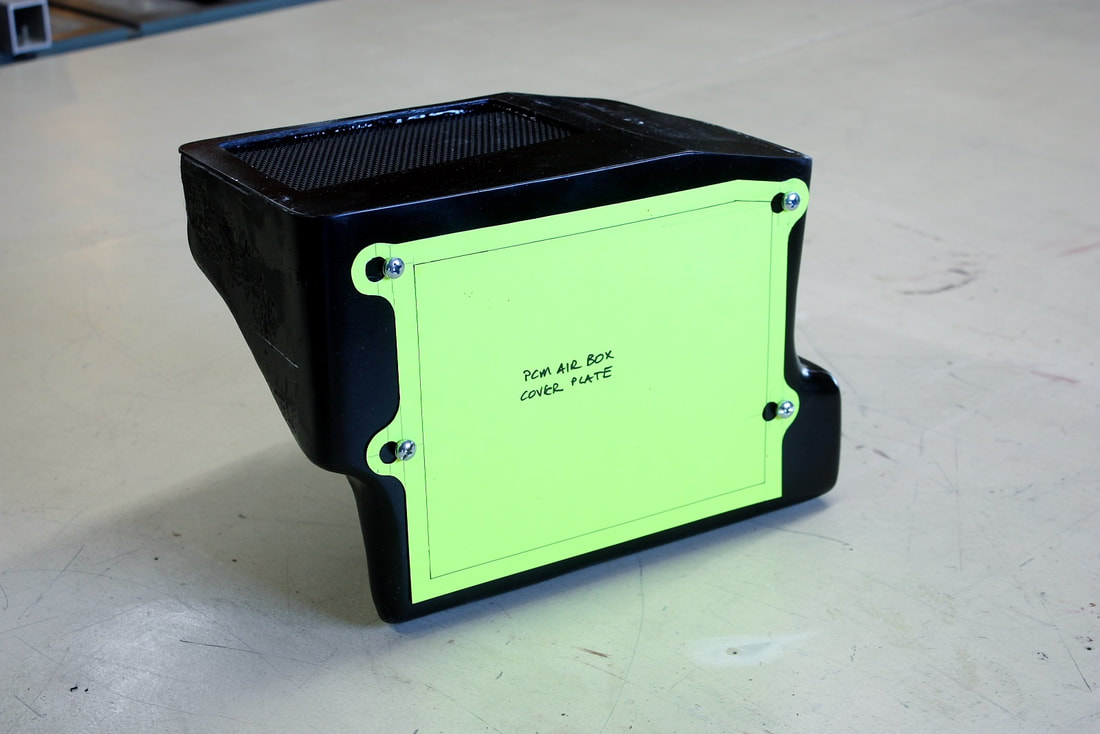
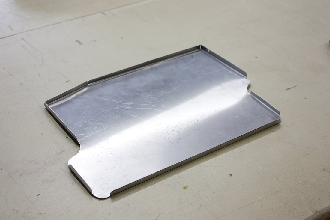
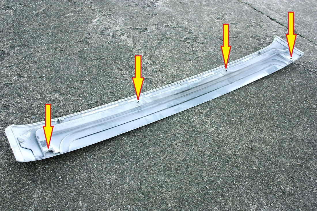
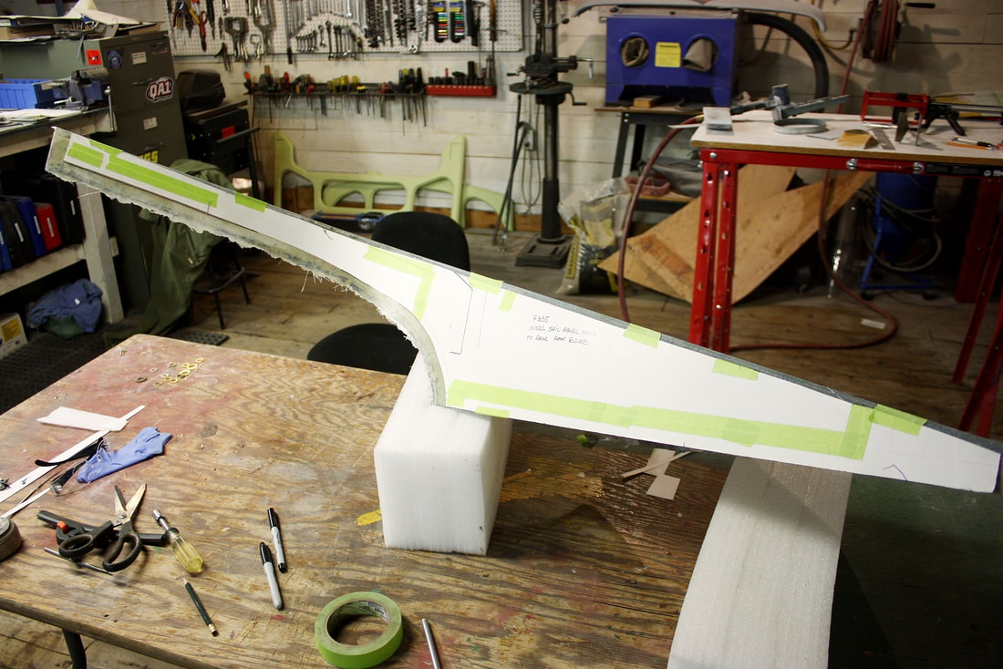
Then, I needed to close up the side of the box with an access panel so I made a template from some neon yellow cardboard:
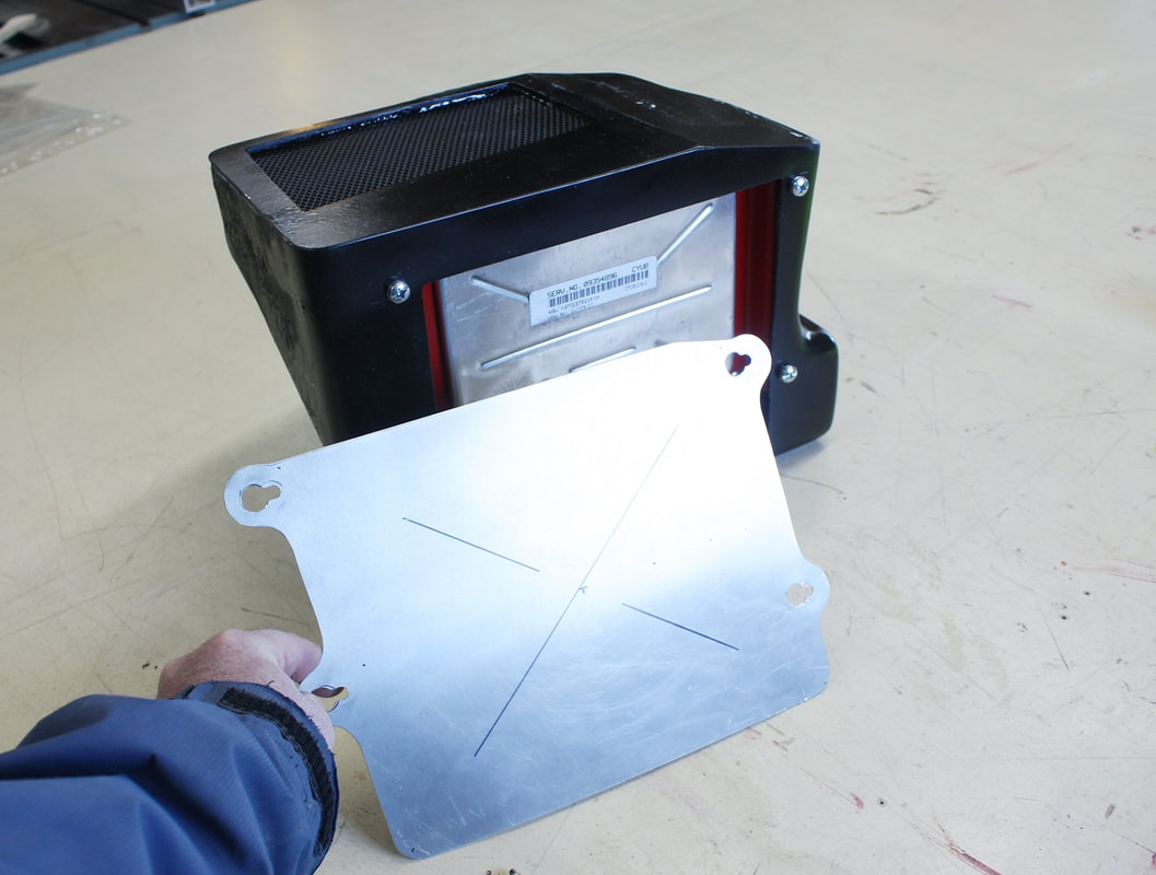
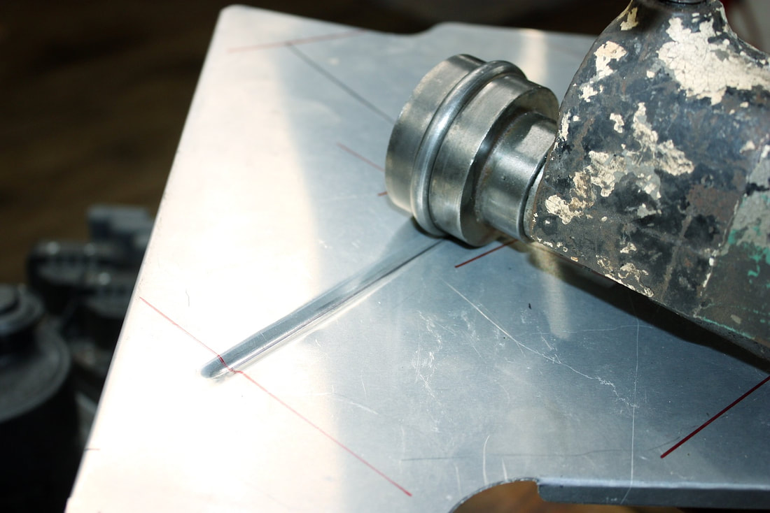
I used some 0.025” aluminium to fabricate the panel, and cut keyholes at the four corners to take advantage of the machine screws already holding the PCM to the box. I also marked an “X” on the panel to guide me when I run the panel through a bead roller to stiffen it:
Next, given the proximity of the PCM box to the exhaust system, I thought it would be wise to make a heat shield to keep radiant heat from unnecessarily warming up the PCM. Again, I used 0.025” thick 6061-T6 aluminium to fabricate it:
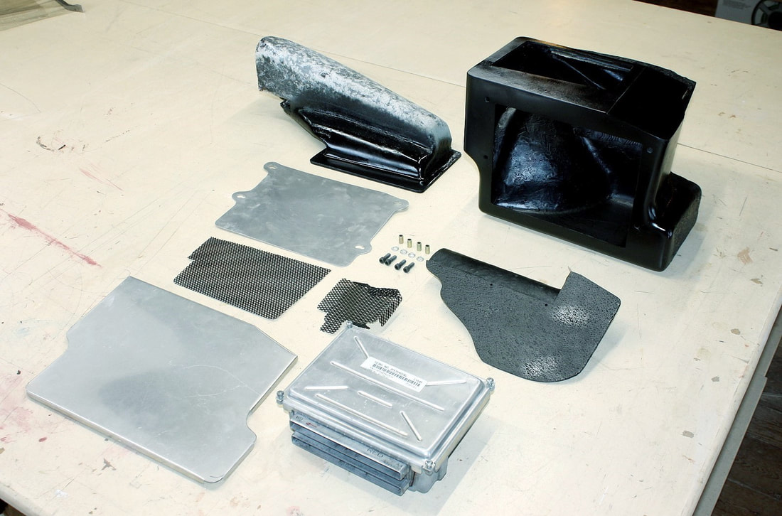
Taken all together, the various parts that make up the PCM box started adding up! The only things missing were the PCM mounting brackets which were painted and still drying:
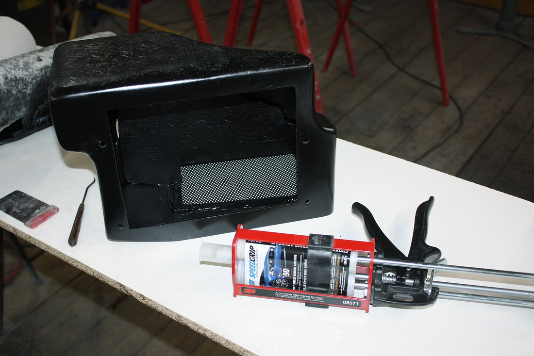
Assembling the box was next on the list so I began by bonding the two screens and the diverter to the inside of the box with epoxy:
Next I mounted the brackets to the PCM, and the PCM to the box (Ooooo… pretty brackets!):
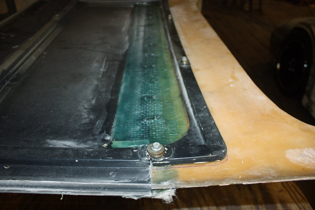
Then I built a mounting bracket to hold the box to the chassis at just the right height to mate up with the scoop:
And securely bolted the box to the frame… it’s not going anywhere!
Next up I needed to install the access panel to close off the box, but I still needed to stiffen the panel and the heat shield with a rolled bead or two. The bead roller has an upper male and a lower female die which are used to imprint a shallow rib into a flat panel:
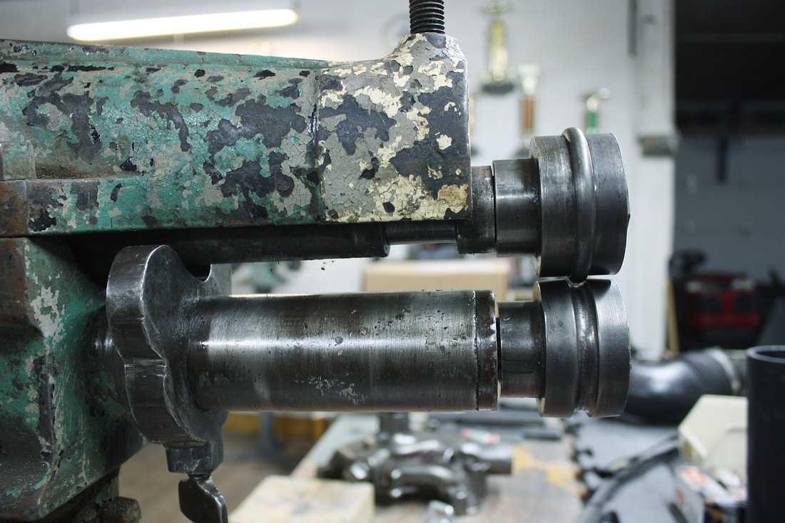
It's dirt simple to use, simply open the jaws, insert the piece, tighten the jaws, and turn the crank:
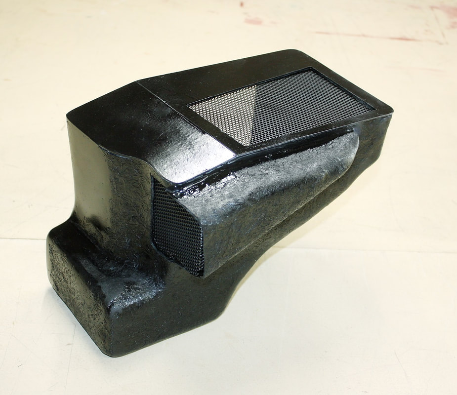
Once they were rolled, I reinstalled both the access panel and heat shield to complete the PCM air box.
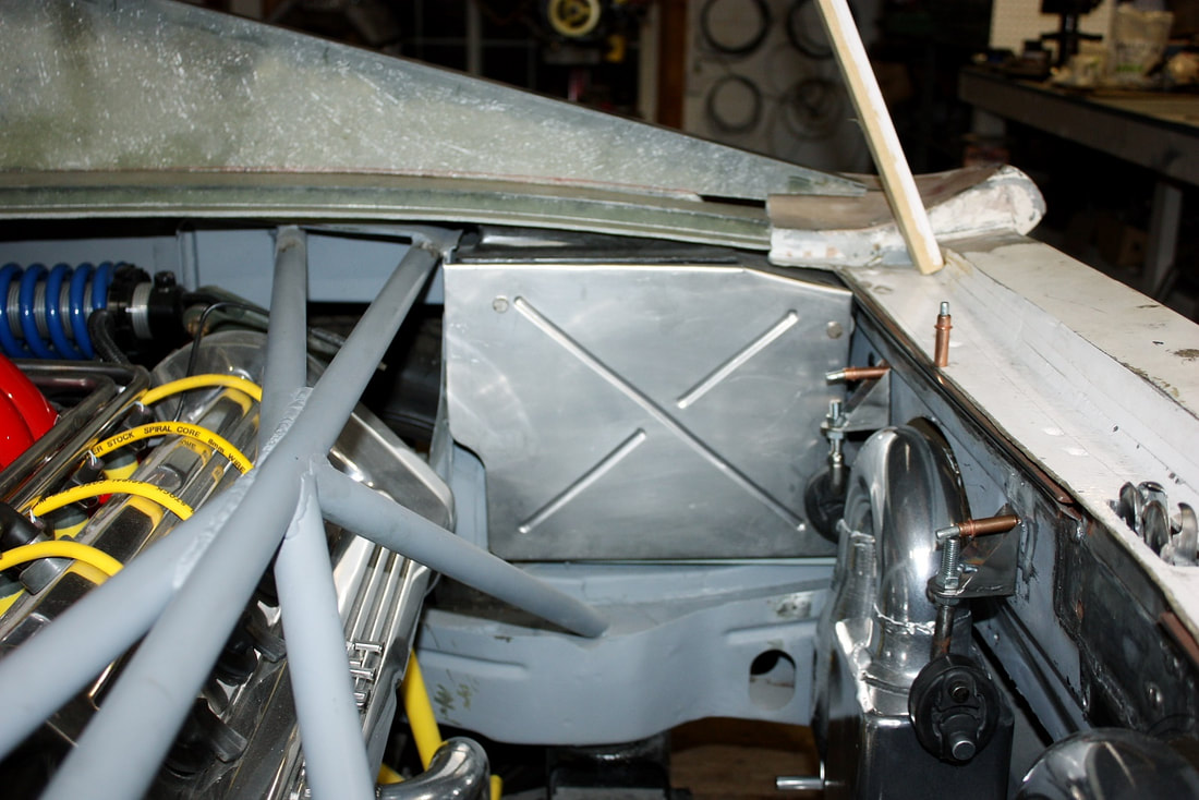
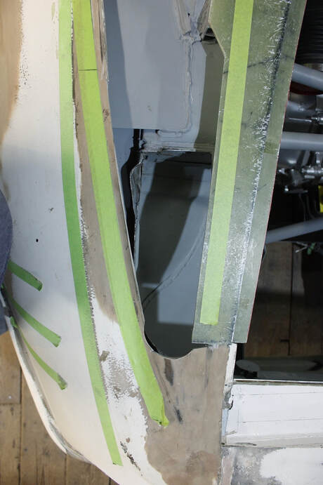
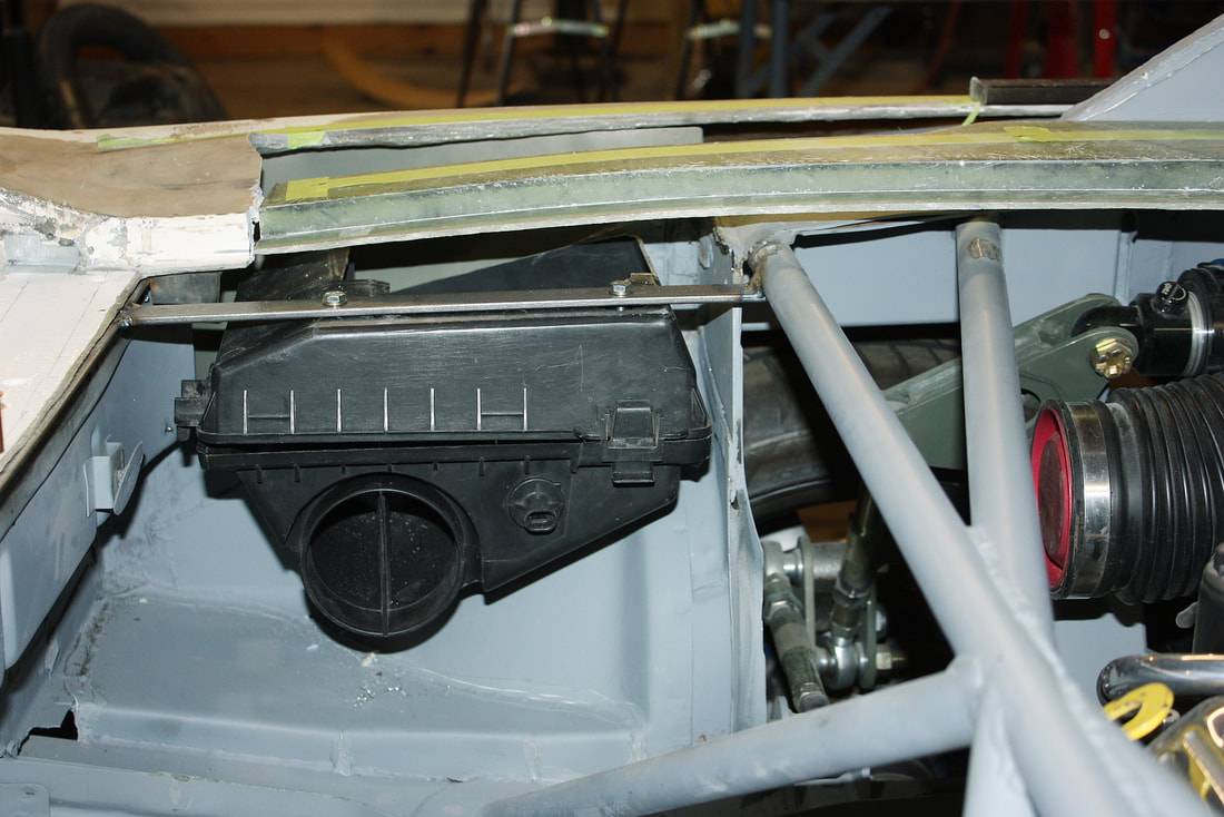
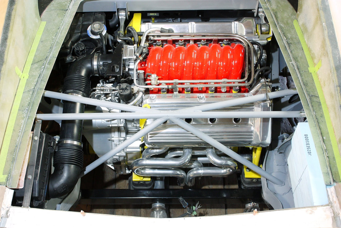
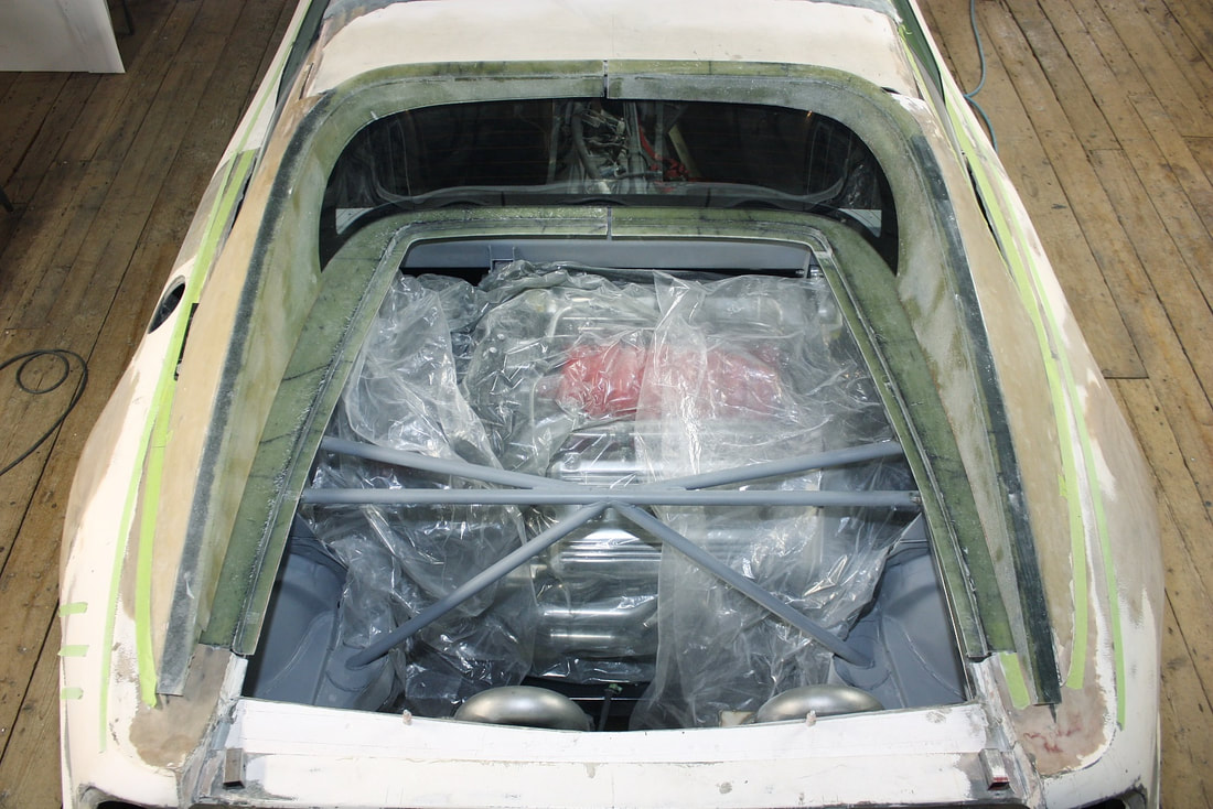
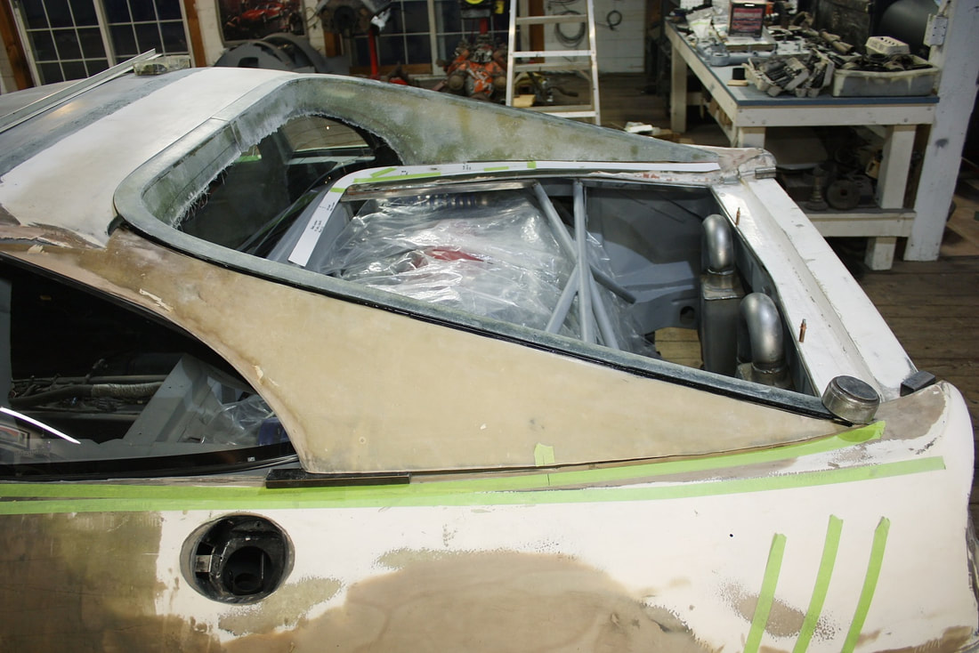
From the photo above, it’s clear to see why I felt a heat shield would be beneficial after I mocked up one of the cat-back pipes:
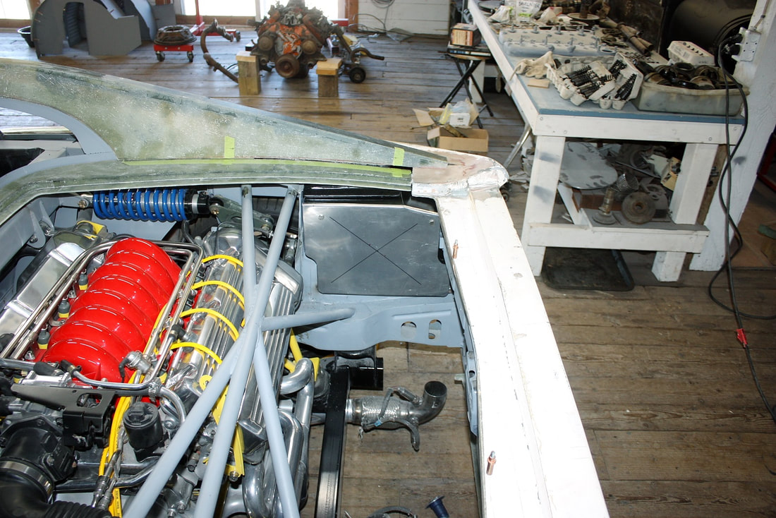
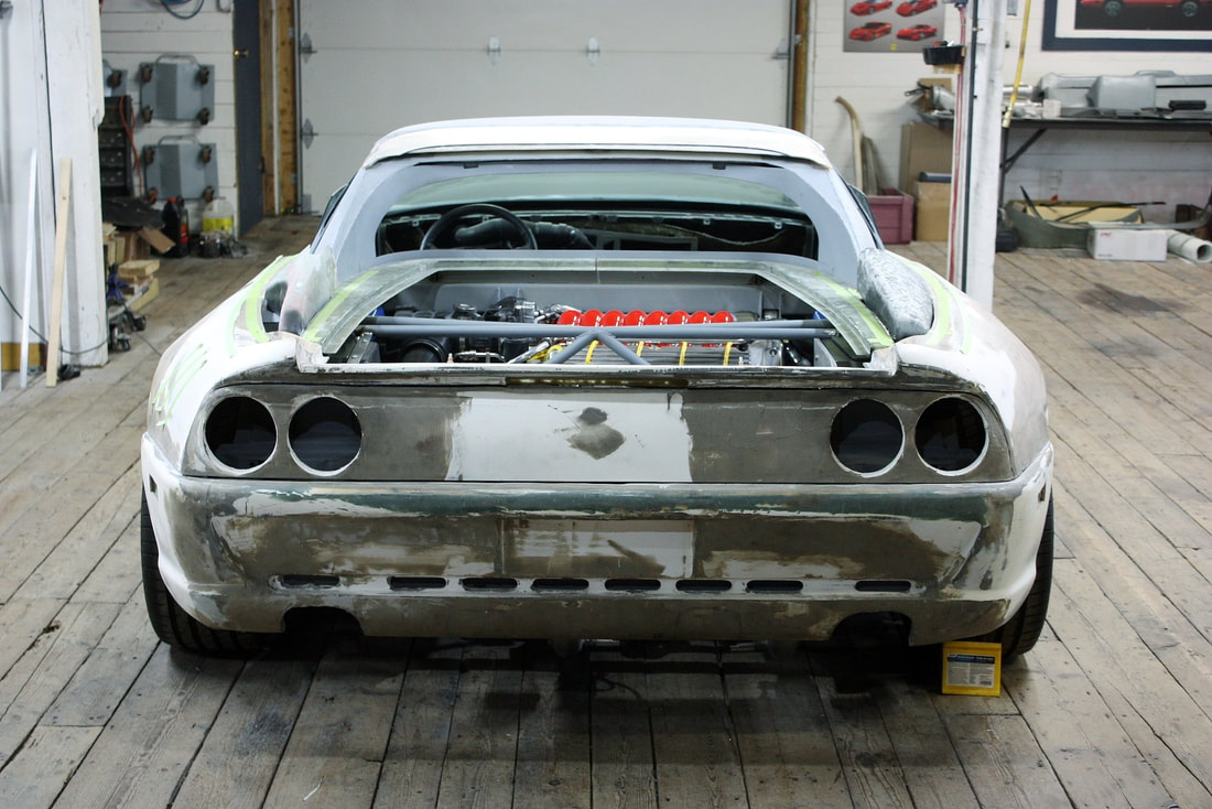
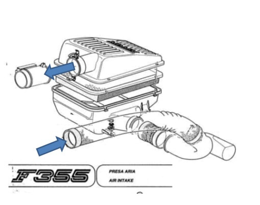
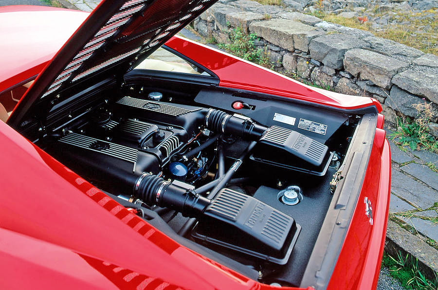
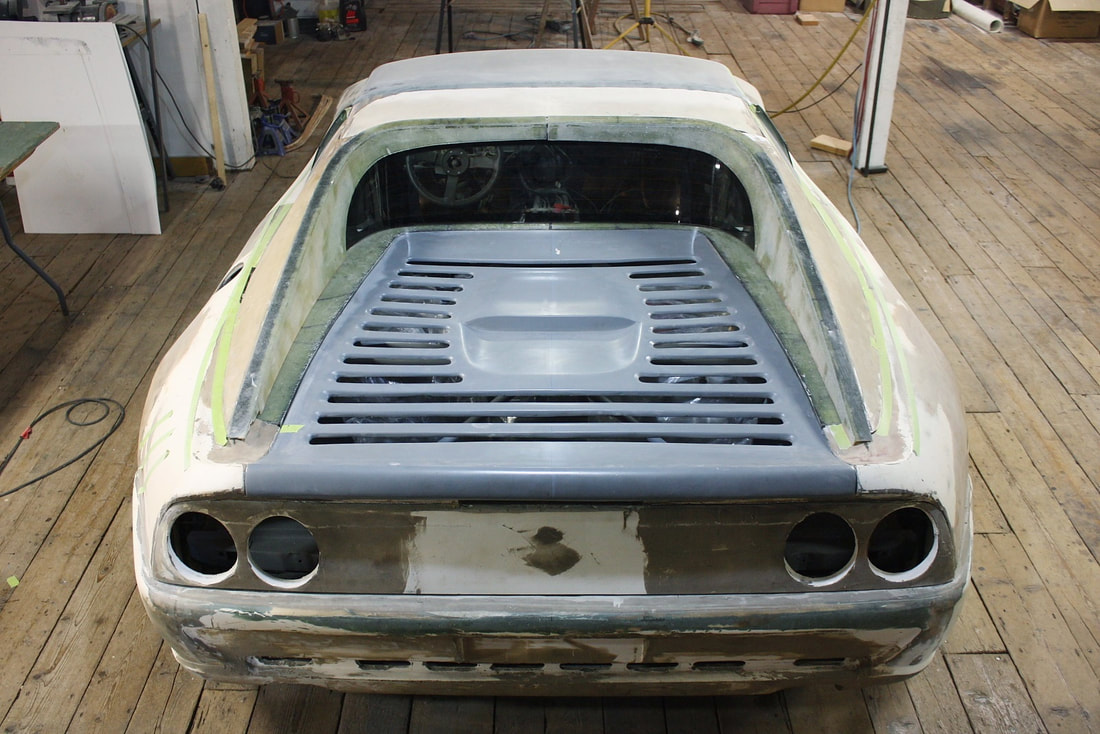
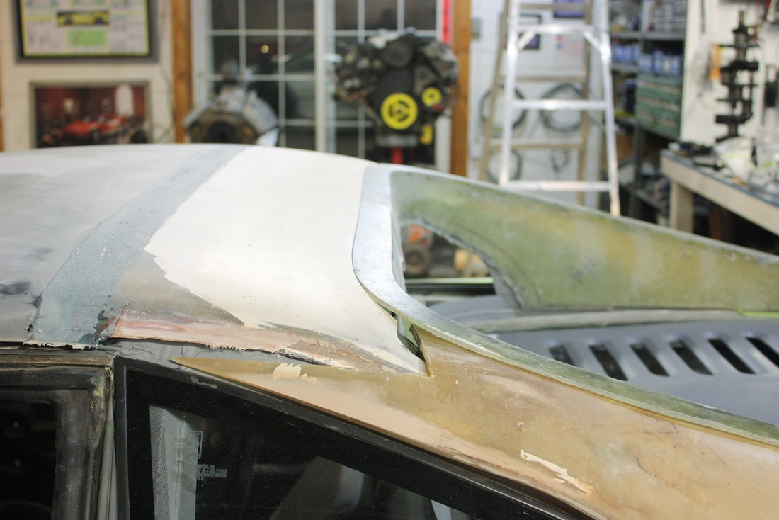
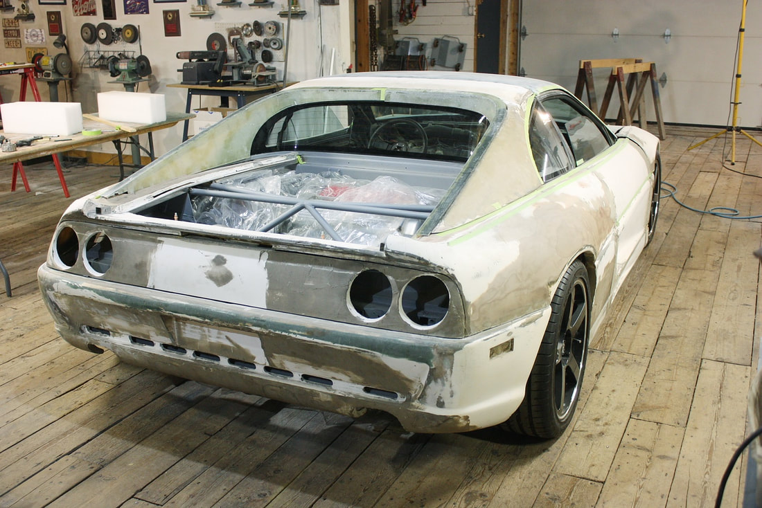
And with that, the two intake systems were pretty much complete. Stepping back and squinting a little, I couldn’t help but notice a certain similarity of the intake layout to the Ferrari F430… with bulging scoops that look out of place on the tops of the rear fenders. I much prefer the look of the F355 with the scoops cleverly hidden under the C-pillars:
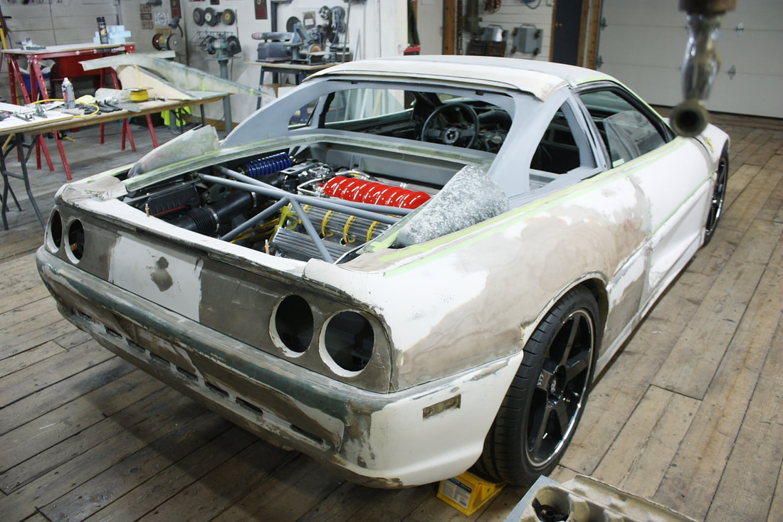
There’s no doubt going this extra mile took a lot more time than I anticipated, mostly because I was starting with a blank canvas. However, if it were going to be done at all, it had to be done before the C-pillars were mounted permanently to the fenders otherwise there would have been no access to the insides of the pillars to fit the scoops properly.
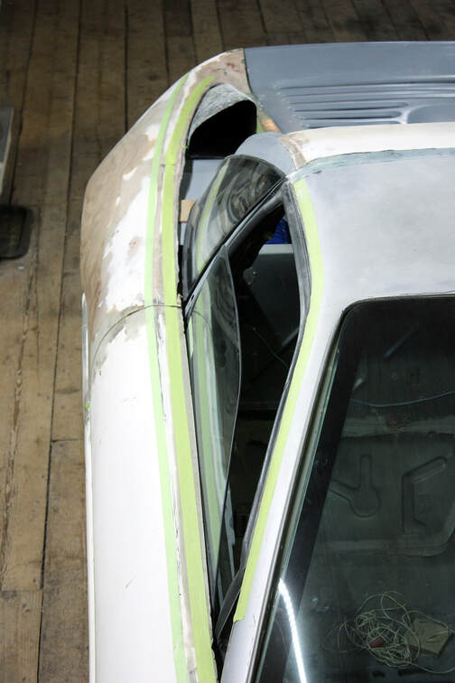
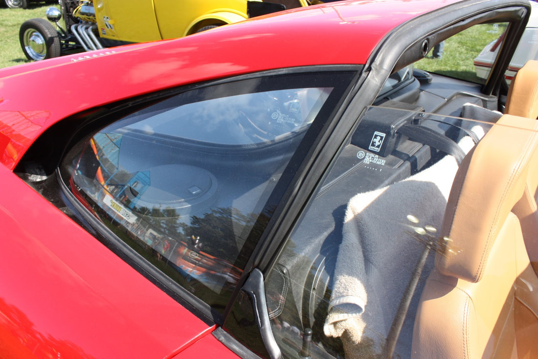
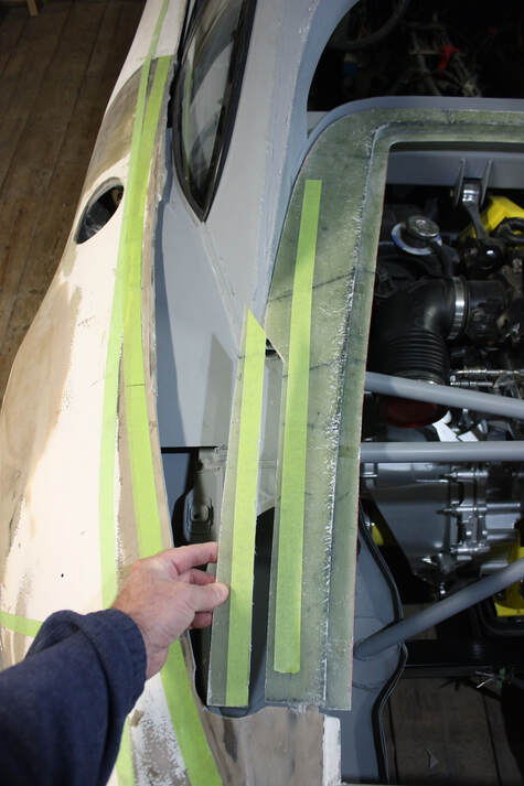
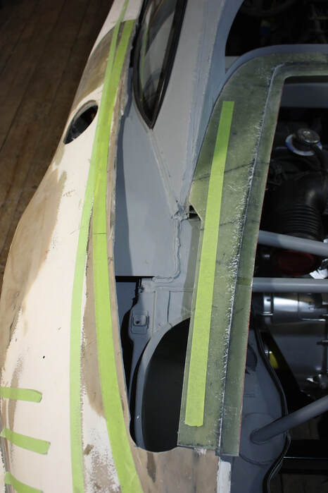
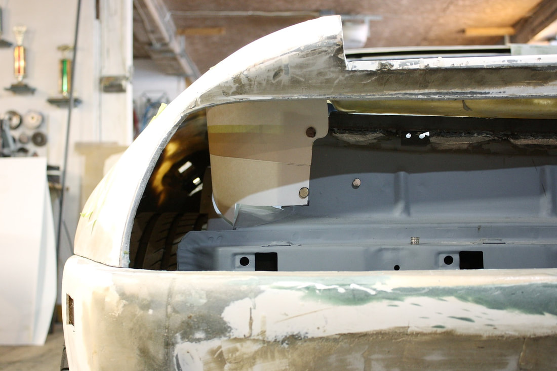
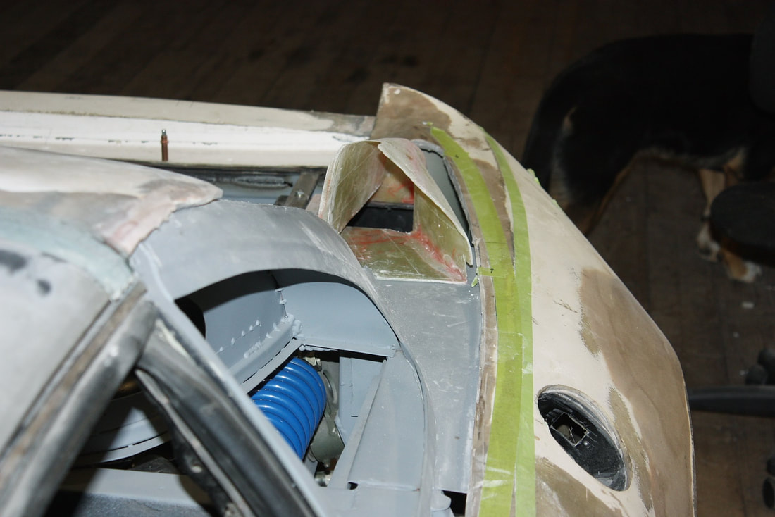
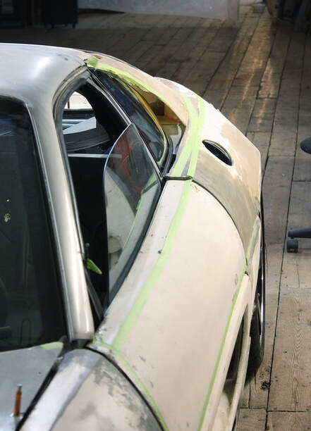
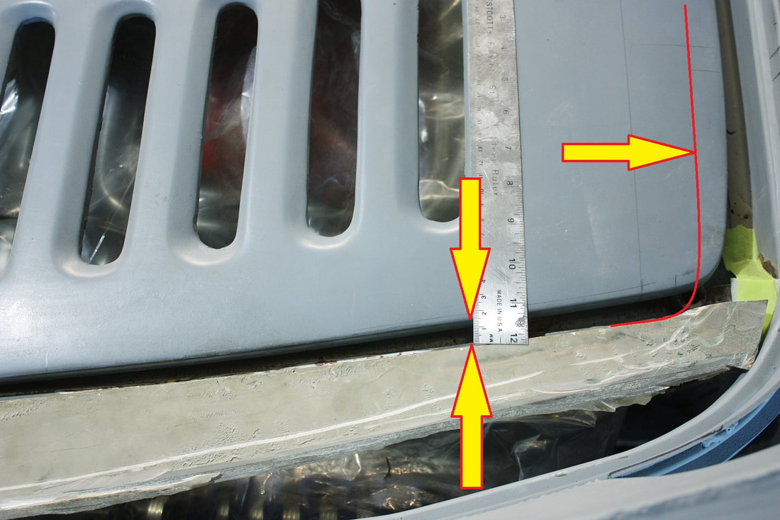
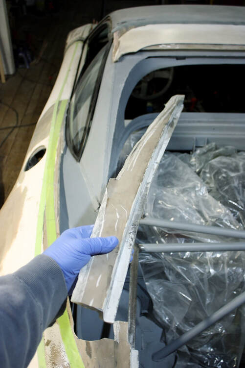
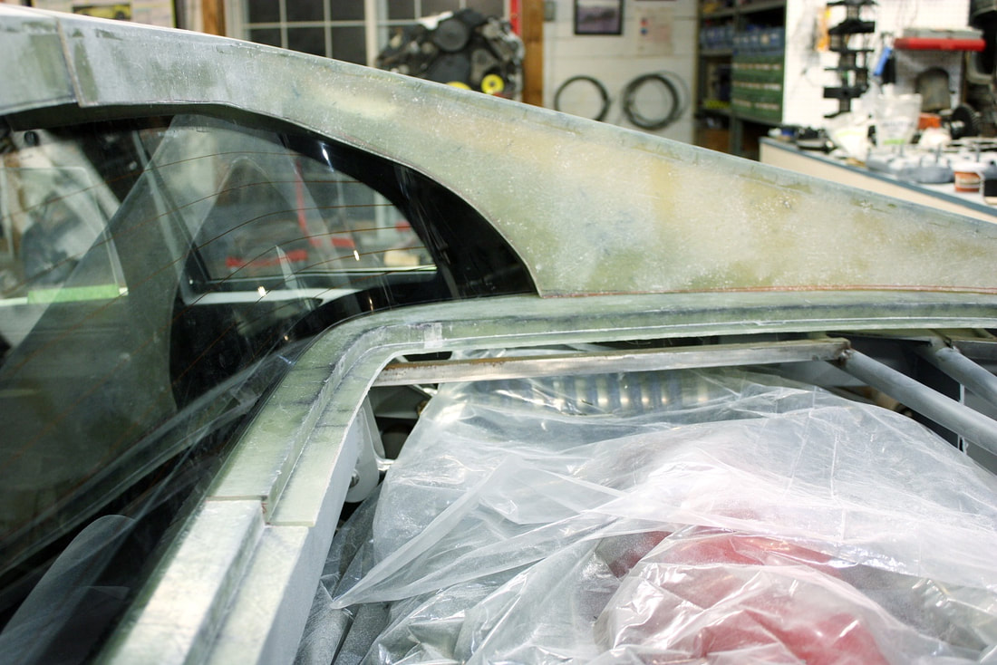
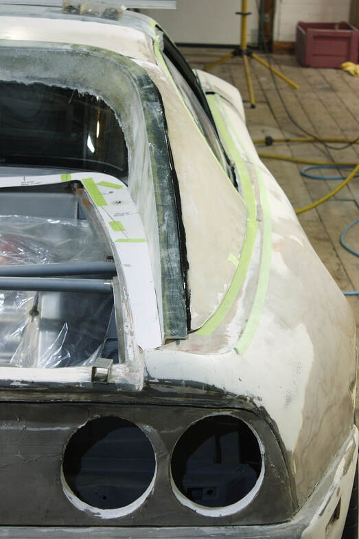
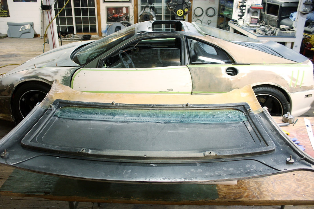
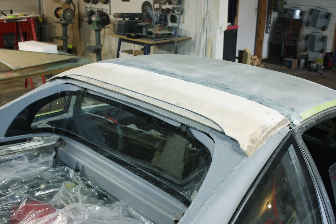
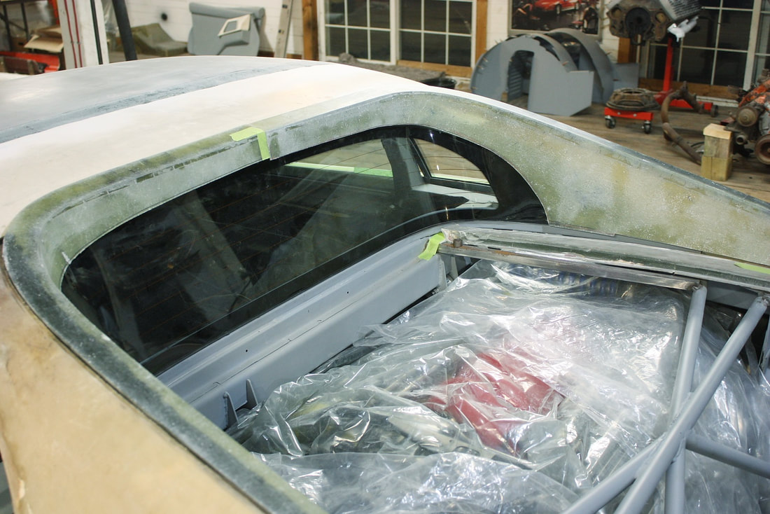
Here’s an interesting photo showing the size of the PCM intake opening as mocked up on the chassis. The increasing curvature toward the rear of the quarter window is also clear too:
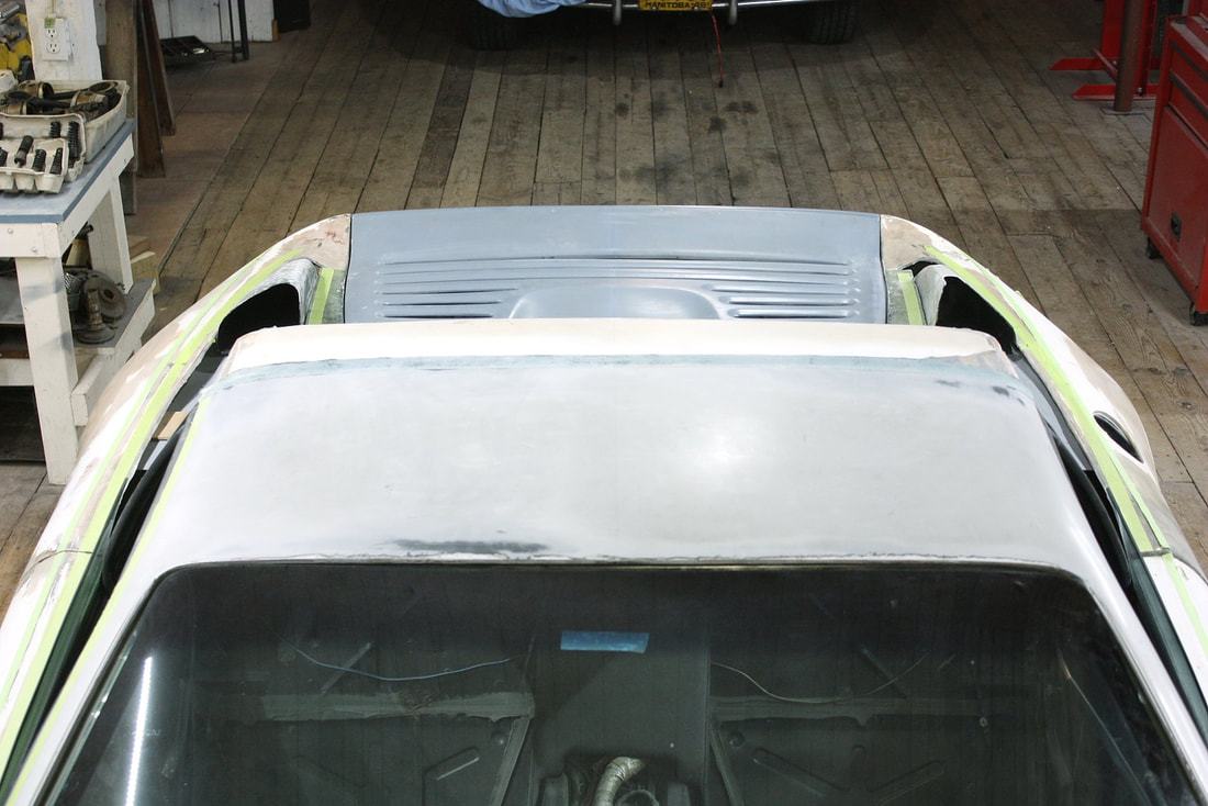
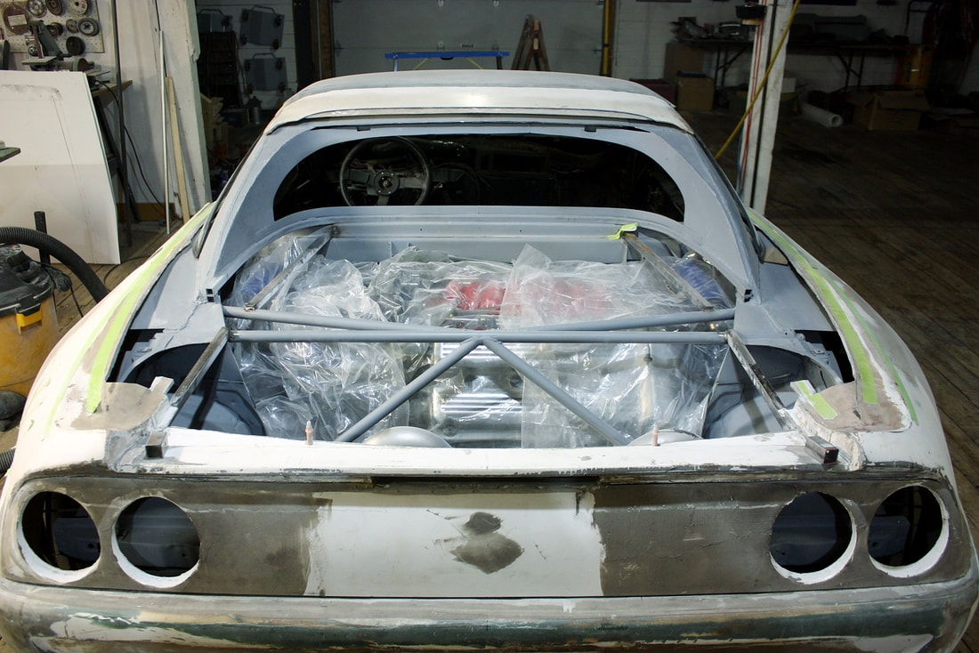
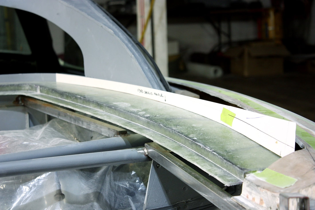
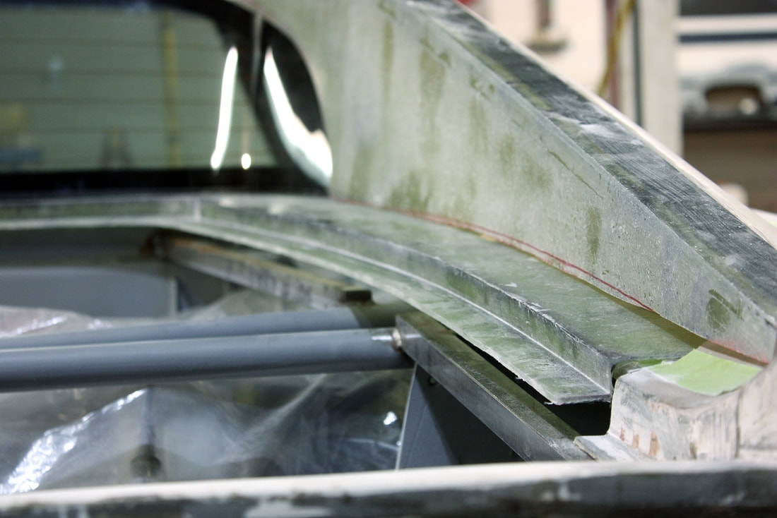
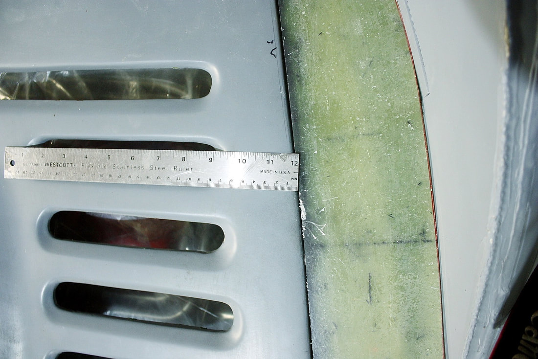
And finally, an upper front view showing most of both scoops, giving an appreciation for just how well Ferrari hid the size of the intakes by making them taller and more slender as they reached forward to the quarter windows:
That pretty much sums up the preparatory work needed before I could advance with mounting the C-pillars to the roof. That’s up next.

 RSS Feed
