I decided it was time to make a couple out-of-sequence posts to catch up on a few topics I’d left unfinished until now.
Mounting the cat-back assemblies rose to the top of the heap because they would determine where the exhaust tips would end up, and I needed that information to continue work on the rear fascia.
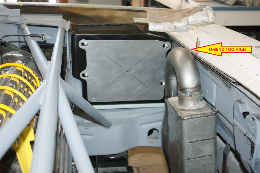
When I designed my exhaust system I ended up with exhaust outlets much closer together than on the authentic F355, so I knew I’d have to make changes to the rear fascia. I did plumb the exhaust system so the tips would be at the correct height, but that left the U-bends between the cats and mufflers too close to the underside of the decklid. But lowering the U-bends would also lower the exhaust tips, so an even greater deviation from stock was in the cards, but it was necessary:
I decided it was time to make a couple out-of-sequence posts to catch up on a few topics I’d left unfinished until now.
Mounting the cat-back assemblies rose to the top of the heap because they would determine where the exhaust tips would end up, and I needed that information to continue work on the rear fascia.
When I designed my exhaust system I ended up with exhaust outlets much closer together than on the authentic F355, so I knew I’d have to make changes to the rear fascia. I did plumb the exhaust system so the tips would be at the correct height, but that left the U-bends between the cats and mufflers too close to the underside of the decklid. But lowering the U-bends would also lower the exhaust tips, so an even greater deviation from stock was in the cards, but it was necessary:
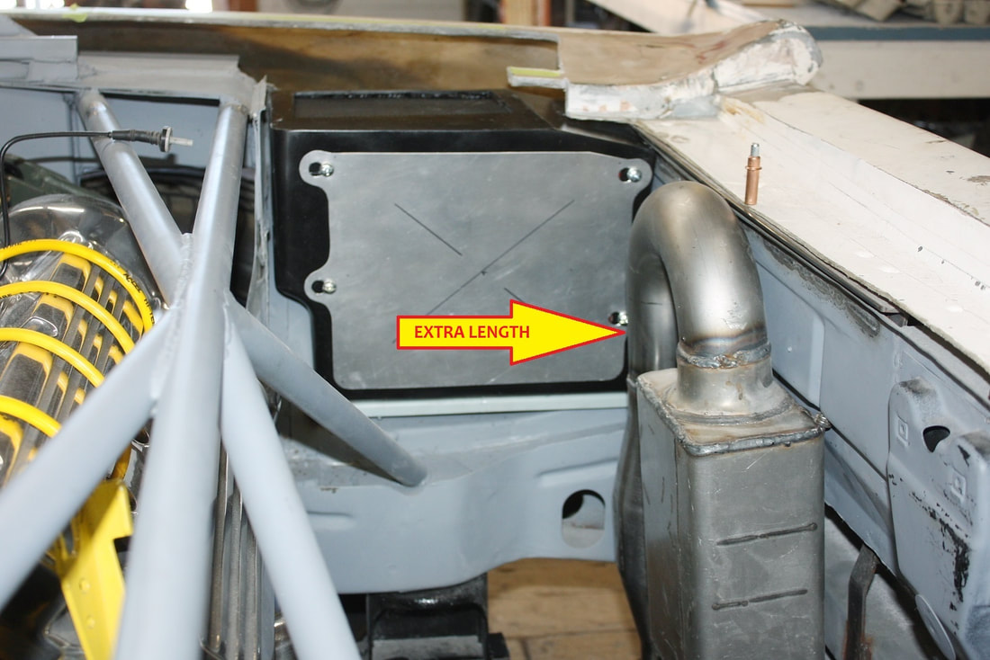
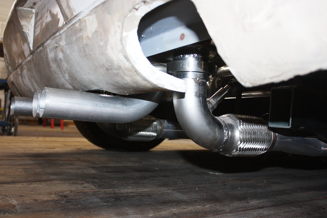
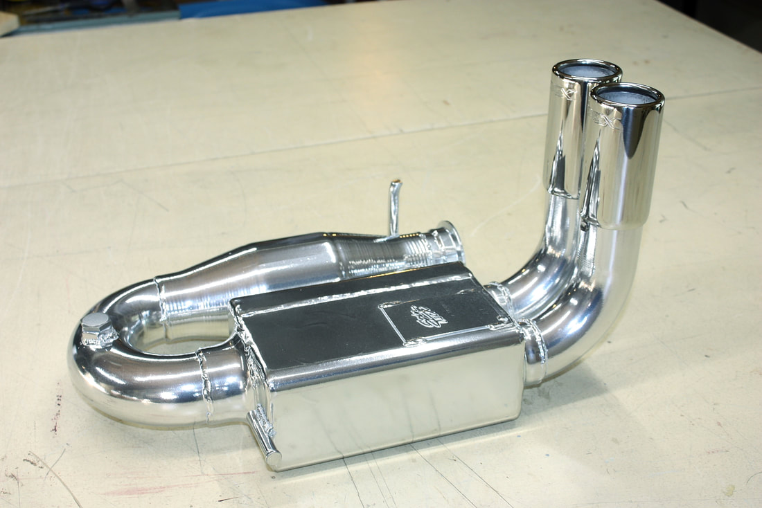
I decided to lower the U-bends by cutting out the straight length of pipe exiting the cat, shown here:
I decided to lower the U-bends by cutting out the straight length of pipe exiting the cat, shown here:
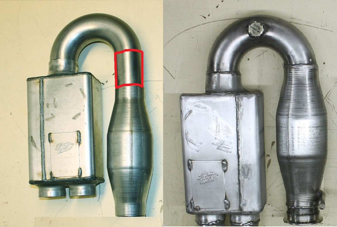
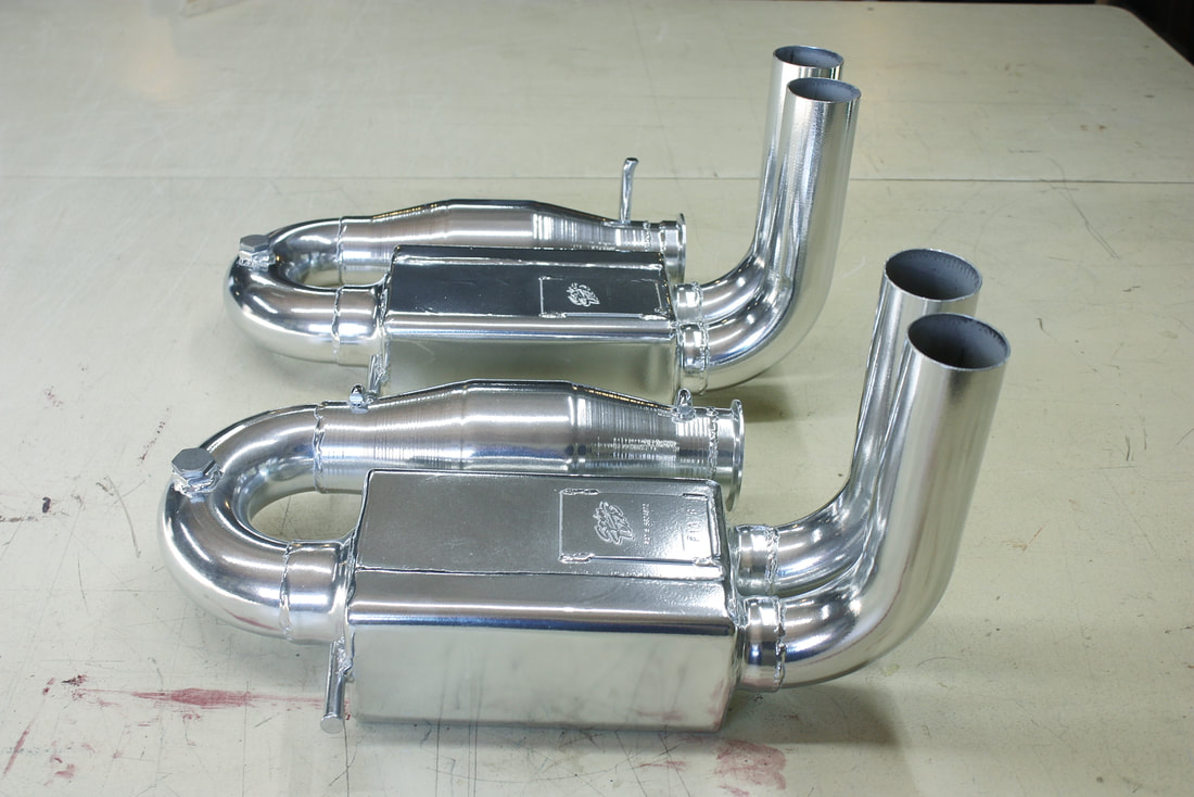
And here’s the “before and after” shot of one of the shortened assemblies:
And here’s the “before and after” shot of one of the shortened assemblies:
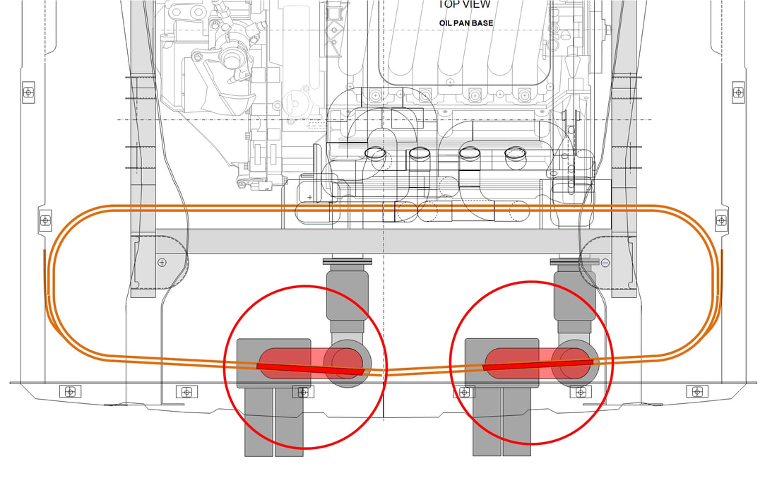
The next dilemma arose when I tried to mock up, align and level the two cat-back systems to each other and to the chassis. I hadn’t noticed in my earlier drawings that the uppermost part of the rear trunk wall joggled inwards and interfered with the U-bends. Here's the top view of the area showing where the interference was in dark red:
The next dilemma arose when I tried to mock up, align and level the two cat-back systems to each other and to the chassis. I hadn’t noticed in my earlier drawings that the uppermost part of the rear trunk wall joggled inwards and interfered with the U-bends. Here's the top view of the area showing where the interference was in dark red:
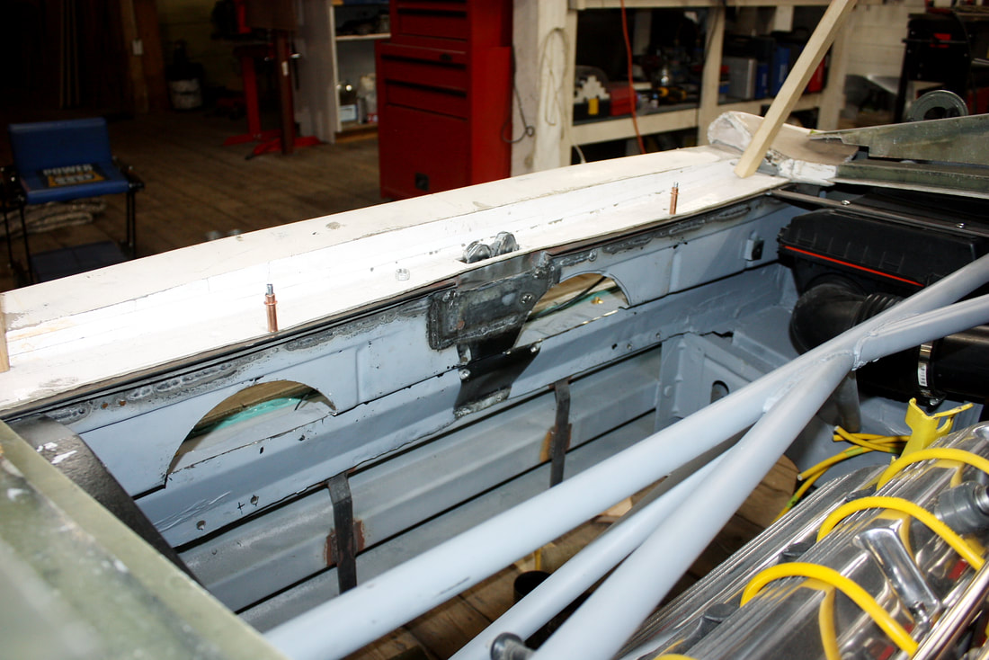
It wasn’t a difficult problem to solve, but it did add more work and created a couple smaller problems to solve later. I simply cut clearance windows in the upper trunk wall for the U-bends like so:
It wasn’t a difficult problem to solve, but it did add more work and created a couple smaller problems to solve later. I simply cut clearance windows in the upper trunk wall for the U-bends like so:
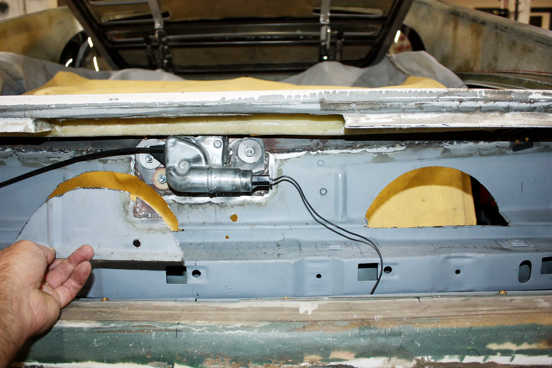
The cuts allowed me to recess the tops of the cat-back systems into the wall to get them upright, level, and aligned. Here’s the view of the cuts from inside the engine bay:
The cuts allowed me to recess the tops of the cat-back systems into the wall to get them upright, level, and aligned. Here’s the view of the cuts from inside the engine bay:
| Next, I had to find a more permanent way to mount the cat-backs other than with magnets on the chassis. Three-point mounts would be the minimum required to be able to align the assemblies in three axes. The main mounting point for each assembly is the V-band clamp attaching the inlet of the cat to the flex joint on the collector. Then, to take the weight off the flex joint, I needed to hang the assemblies from higher up in the chassis. That meant scouring the internet for ideas on how to isolate the cat-backs from the chassis to prevent the noise from transferring to the frame. I came across these universal rubber donuts at NAPA as a starting point: | 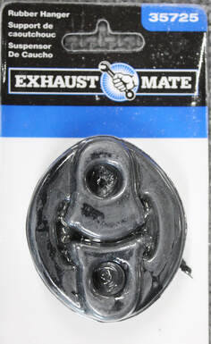 |
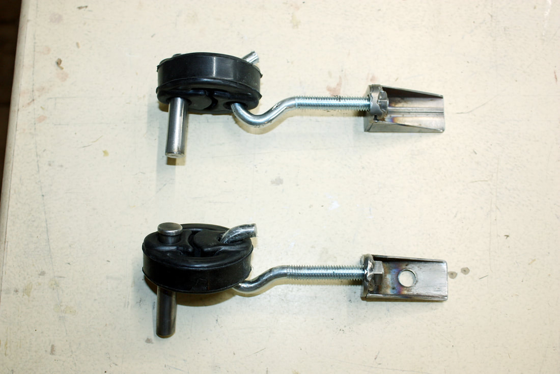
I fabbed up some prototype metal hanger rods to weld to the mufflers, some adjustable length eye hooks, and some brackets to attach to the chassis. The threaded rods would let me raise, lower or twist the cat-backs into alignment with the flex joints providing some spring force:
I fabbed up some prototype metal hanger rods to weld to the mufflers, some adjustable length eye hooks, and some brackets to attach to the chassis. The threaded rods would let me raise, lower or twist the cat-backs into alignment with the flex joints providing some spring force:
After finding the ideal placement of the brackets on the rear trunk wall, I welded the rods to the mufflers and cats and then mocked up both cat-backs a couple times to ensure the alignment was repeatable and not just a fluke. In this next photo the chassis brackets were simply Cleco’ed in place:
After finding the ideal placement of the brackets on the rear trunk wall, I welded the rods to the mufflers and cats and then mocked up both cat-backs a couple times to ensure the alignment was repeatable and not just a fluke. In this next photo the chassis brackets were simply Cleco’ed in place:
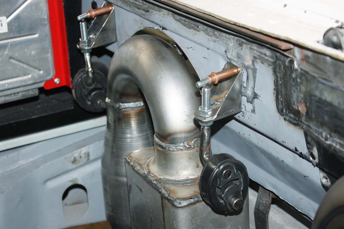
And here, both cat-backs are hung and aligned, with the exhaust outlets properly centered and spaced. Having two adjustable upper hangers per assembly, combined with the additional flexibility of the braided steel joints below made alignment easy-peasy:
And here, both cat-backs are hung and aligned, with the exhaust outlets properly centered and spaced. Having two adjustable upper hangers per assembly, combined with the additional flexibility of the braided steel joints below made alignment easy-peasy:
Stepping back, this photo shows how much difference there will be between the authentic Ferrari’s exhaust locations (note the fiberglass cut-outs), and where mine will be. The benefit of the relocated exhausts is that they will leave lots of room for left and right diffusers in a redesigned roll pan:
Stepping back, this photo shows how much difference there will be between the authentic Ferrari’s exhaust locations (note the fiberglass cut-outs), and where mine will be. The benefit of the relocated exhausts is that they will leave lots of room for left and right diffusers in a redesigned roll pan:
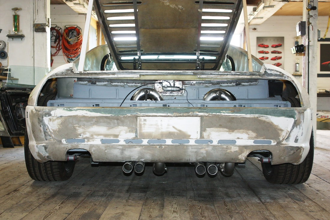
From this next view, it’s easy to see that the rear fascia simply wasn’t going to cut it anyway. It’s bobbed way too short for the even lower-hanging collectors:
From this next view, it’s easy to see that the rear fascia simply wasn’t going to cut it anyway. It’s bobbed way too short for the even lower-hanging collectors:
With the cat-backs finalized, I was able to sort out another piece of the puzzle: mounting the post-cat oxygen sensors needed to feed the powertrain control module. They had to be mounted in the U-bends between the cats and mufflers, so there were really only two choices: at the top of the U-bends either pointing toward the engine, or pointing rearward. I chose to point them backwards, hiding them behind the tail light panel rather than having them jut out into the engine bay:
With the cat-backs finalized, I was able to sort out another piece of the puzzle: mounting the post-cat oxygen sensors needed to feed the powertrain control module. They had to be mounted in the U-bends between the cats and mufflers, so there were really only two choices: at the top of the U-bends either pointing toward the engine, or pointing rearward. I chose to point them backwards, hiding them behind the tail light panel rather than having them jut out into the engine bay:
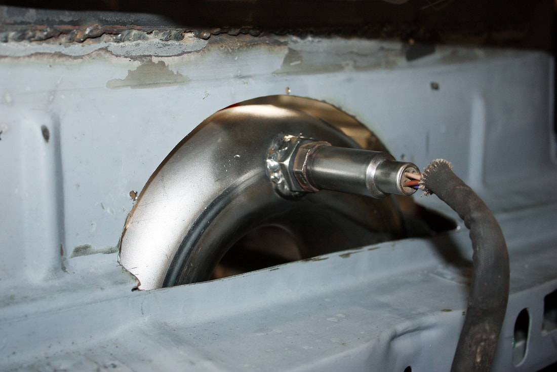
I drilled a hole and welded a sensor bung in each U-bend, then mocked up the sensors:
I drilled a hole and welded a sensor bung in each U-bend, then mocked up the sensors:
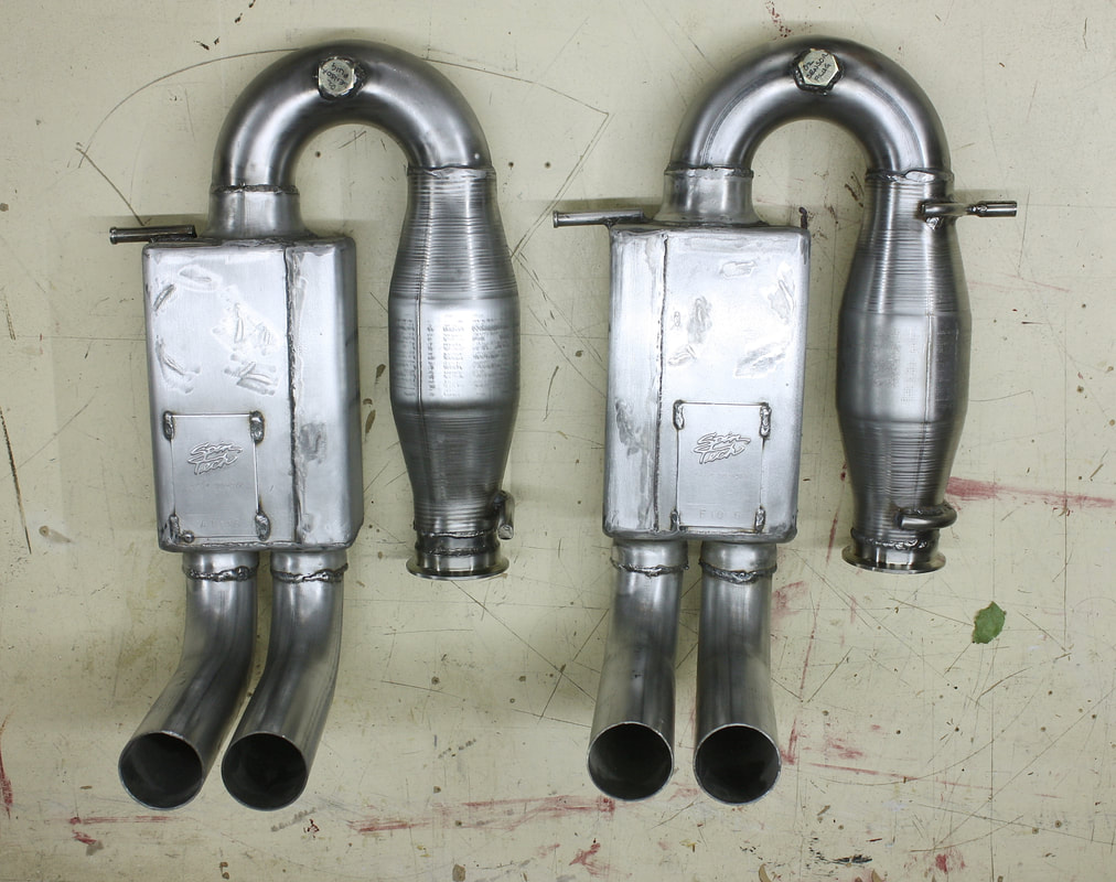
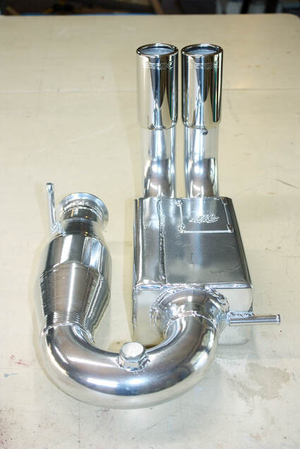
At this point, the cat-backs were finally ready for ceramic coating to keep the heat in, and provide corrosion protection. Here are the bare steel assemblies with the hanger rods and o2 sensor bungs welded in:
At this point, the cat-backs were finally ready for ceramic coating to keep the heat in, and provide corrosion protection. Here are the bare steel assemblies with the hanger rods and o2 sensor bungs welded in:
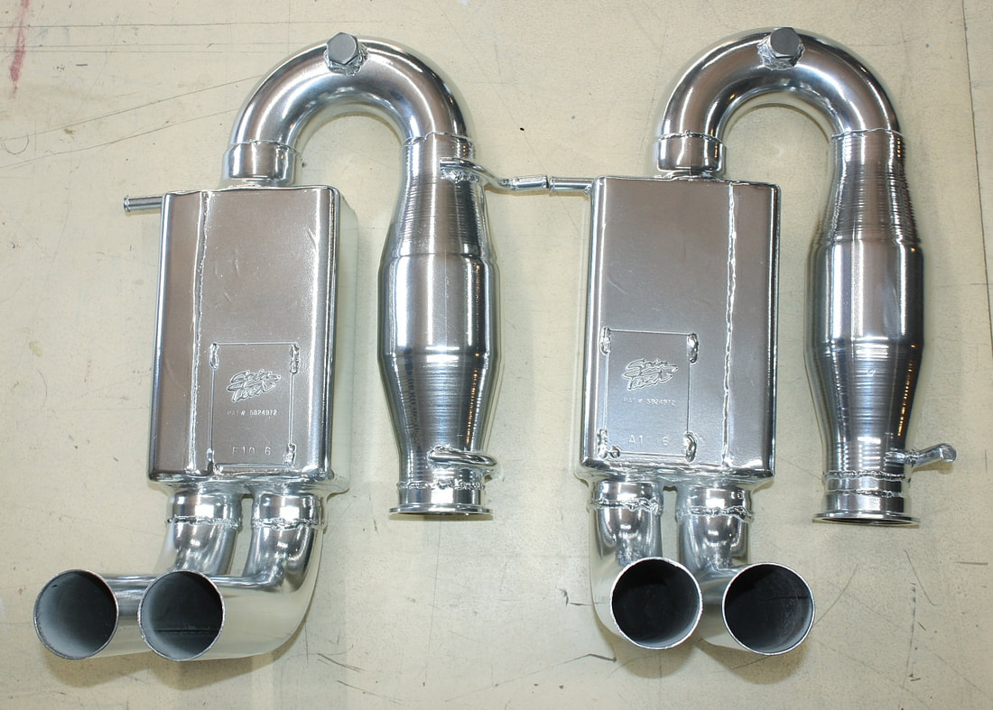
I dropped them off at Hi-Tech Mechanical and Coatings in Nine Mile River (the same place I had the headers done) and waited for the call that they were done. When they were, I jumped into my Stinger 308 replica and enjoyed a nice late summer drive to pick them up… a 3 hour return trip. I wasn’t disappointed:
I dropped them off at Hi-Tech Mechanical and Coatings in Nine Mile River (the same place I had the headers done) and waited for the call that they were done. When they were, I jumped into my Stinger 308 replica and enjoyed a nice late summer drive to pick them up… a 3 hour return trip. I wasn’t disappointed:
While I waited, I ordered four XForce 2.25” inlet x 2.5” outlet x 4” long polished stainless tips from Summit:
While I waited, I ordered four XForce 2.25” inlet x 2.5” outlet x 4” long polished stainless tips from Summit:
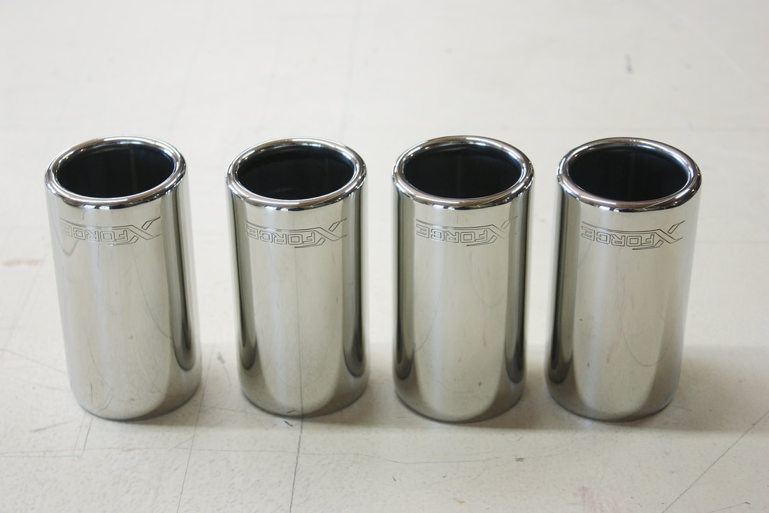
They’re simple, but they completed the look. They slipped on the cat-backs like a glove and added that extra bling-factor I was looking for:
They’re simple, but they completed the look. They slipped on the cat-backs like a glove and added that extra bling-factor I was looking for:
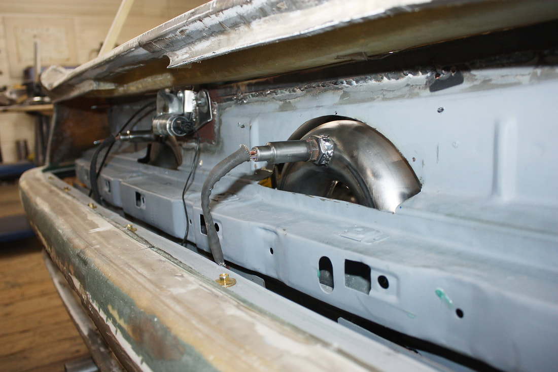
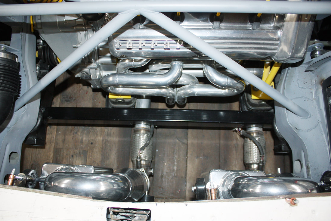
It didn’t take long to mock everything back up and take a few more glamour-shots (well, as glamorous as you can get with a primer-coloured engine bay!). Here are both systems nestled back where they belong. Notice the U-bends are significantly lower:
It didn’t take long to mock everything back up and take a few more glamour-shots (well, as glamorous as you can get with a primer-coloured engine bay!). Here are both systems nestled back where they belong. Notice the U-bends are significantly lower:
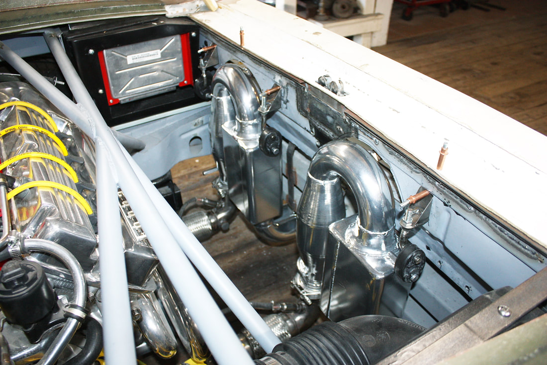
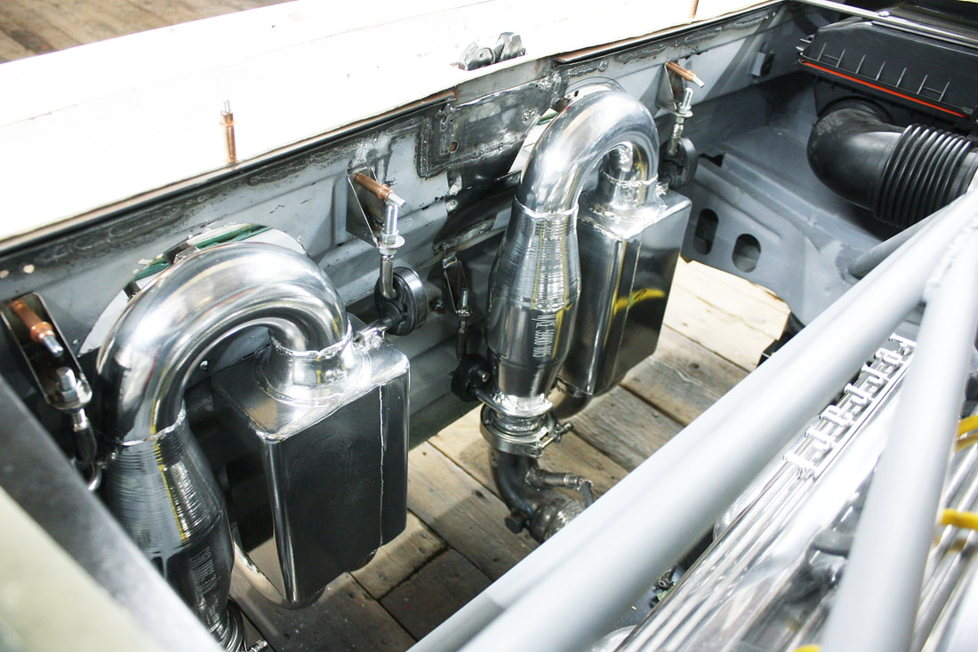
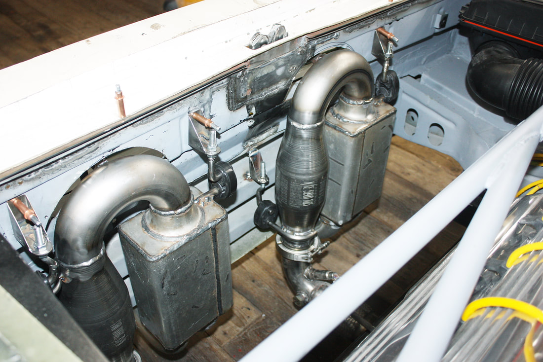
And here’s the top view looking down. I’ll be fabricating a tubular mesh heat shield to protect unsuspecting hands from accidentally touching either U-bend. I think I can make something with my shrinker/stretcher that will look nice:
And here’s the top view looking down. I’ll be fabricating a tubular mesh heat shield to protect unsuspecting hands from accidentally touching either U-bend. I think I can make something with my shrinker/stretcher that will look nice:
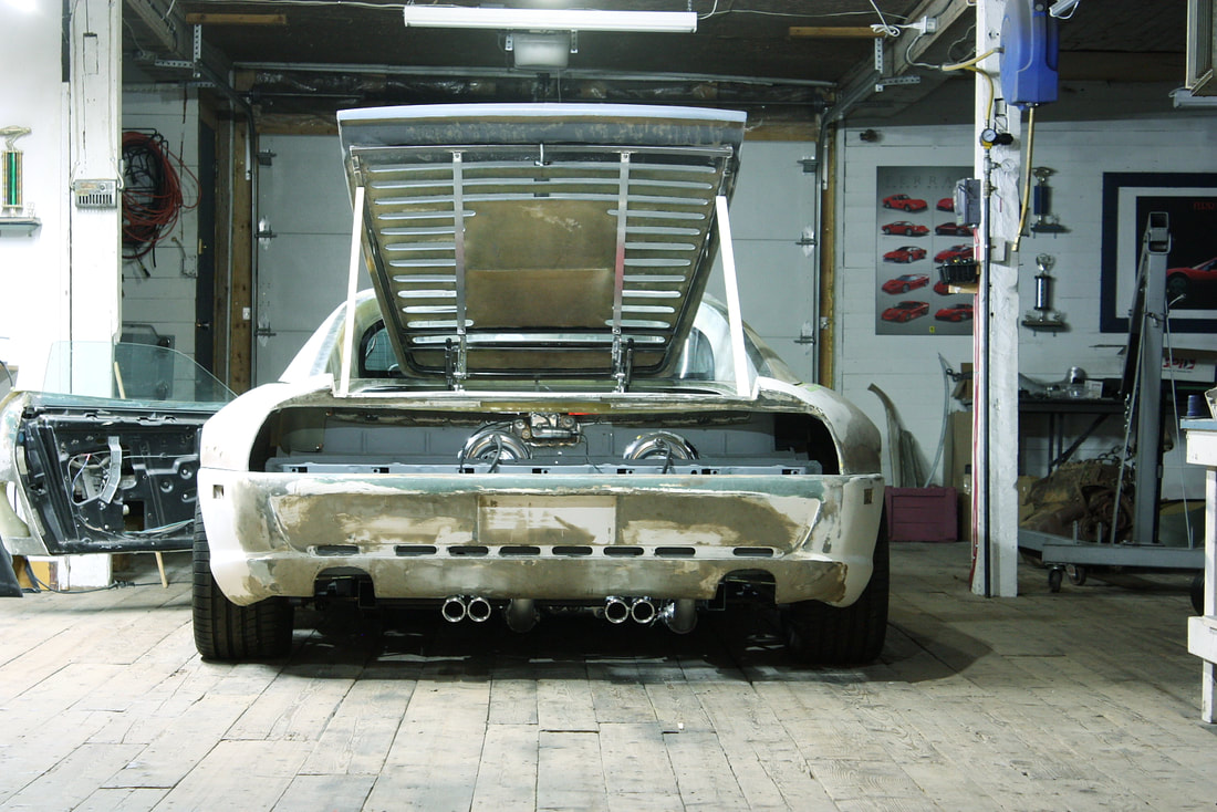
And finally, here's a pic of the exhaust tips, albeit sticking out a little too far for my tastes. There’s plenty of room to shorten the outlet pipes, but I think I’ll wait until I’ve redesigned the rear fascia before finalizing their lengths:
And finally, here's a pic of the exhaust tips, albeit sticking out a little too far for my tastes. There’s plenty of room to shorten the outlet pipes, but I think I’ll wait until I’ve redesigned the rear fascia before finalizing their lengths:
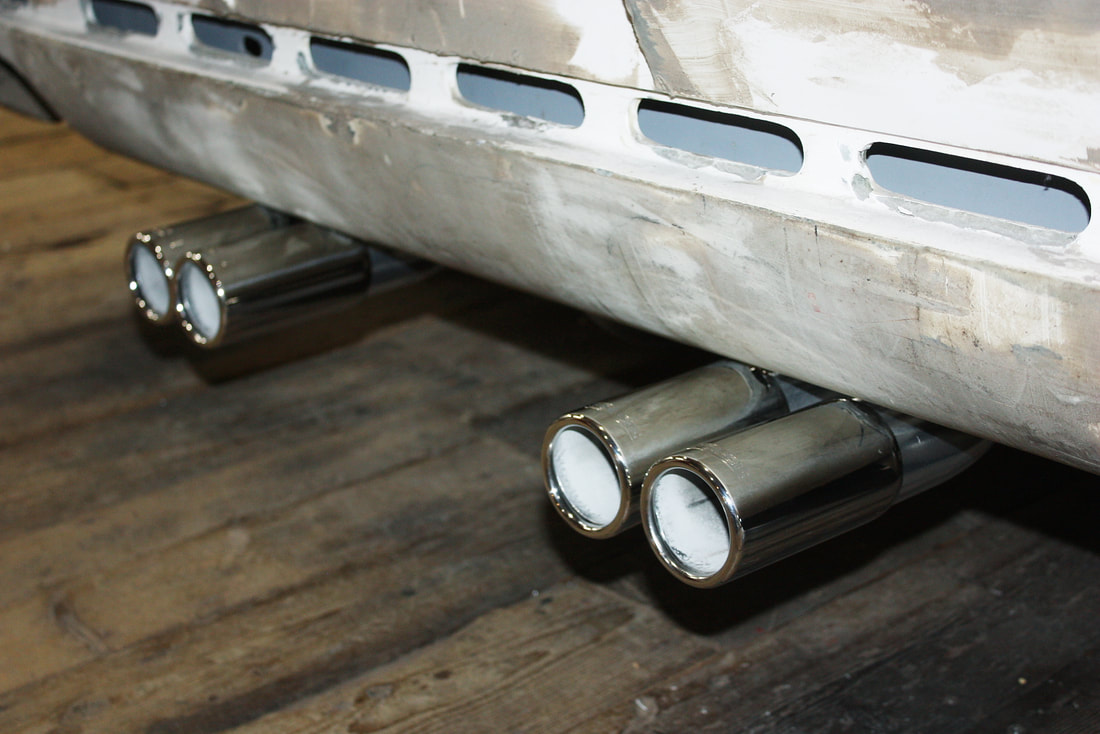
Imagining a pair of wide diffusers in the area where the authentic F355's exhaust outlets are is pretty easy from this view:
Imagining a pair of wide diffusers in the area where the authentic F355's exhaust outlets are is pretty easy from this view:
Next up: some more odds and ends.
Next up: some more odds and ends.
 RSS Feed
