This post is closely related to my last post on the throttle cable. It deals with finding a place for the digital cruise control servo, mounting it, and connecting it to the throttle.
The original cruise control system in the Fiero was electro-pneumatic. A hall-effect Vehicle Speed Sensor (VSS) in the transmission sent a signal to the speedometer where it was processed into various outputs including one to a cruise control module that controlled a vacuum solenoid to a pneumatic servo attached to the throttle via a cable. The vacuum reservoir (a tin can prone to rusting), and the myriad steel and rubber vacuum lines were prone to leaks. The vacuum solenoid was prone to failure, and the flexible circuit board on the back of the instrument panel (the hub of the cruise control signals) was susceptible to corrosion and broken contacts.
I decided to upgrade the cruise control to an electro-mechanical system, which was an easy decision since the digital servo came attached to one of the Northstar engines I bought several years ago. Here’s what it looks like:
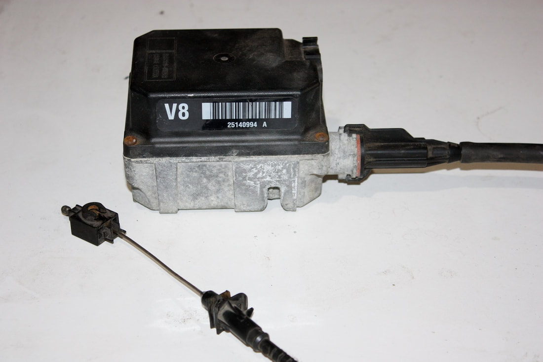
This one unit combines the processor and the servo into a single unit, and does away with all of the vacuum plumbing. Furthermore, the speed signal is sent to it via the PCM rather than the speedometer.
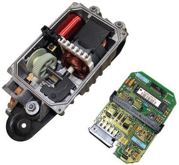
The processor controls an electric motor that drives a worm gear attached to a bobbin of ribbon (orange part below). The motor reels in or lets out the ribbon which is attached to the throttle via a second throttle cable:
This one unit combines the processor and the servo into a single unit, and does away with all of the vacuum plumbing. Furthermore, the speed signal is sent to it via the PCM rather than the speedometer.
The processor controls an electric motor that drives a worm gear attached to a bobbin of ribbon (orange part below). The motor reels in or lets out the ribbon which is attached to the throttle via a second throttle cable:
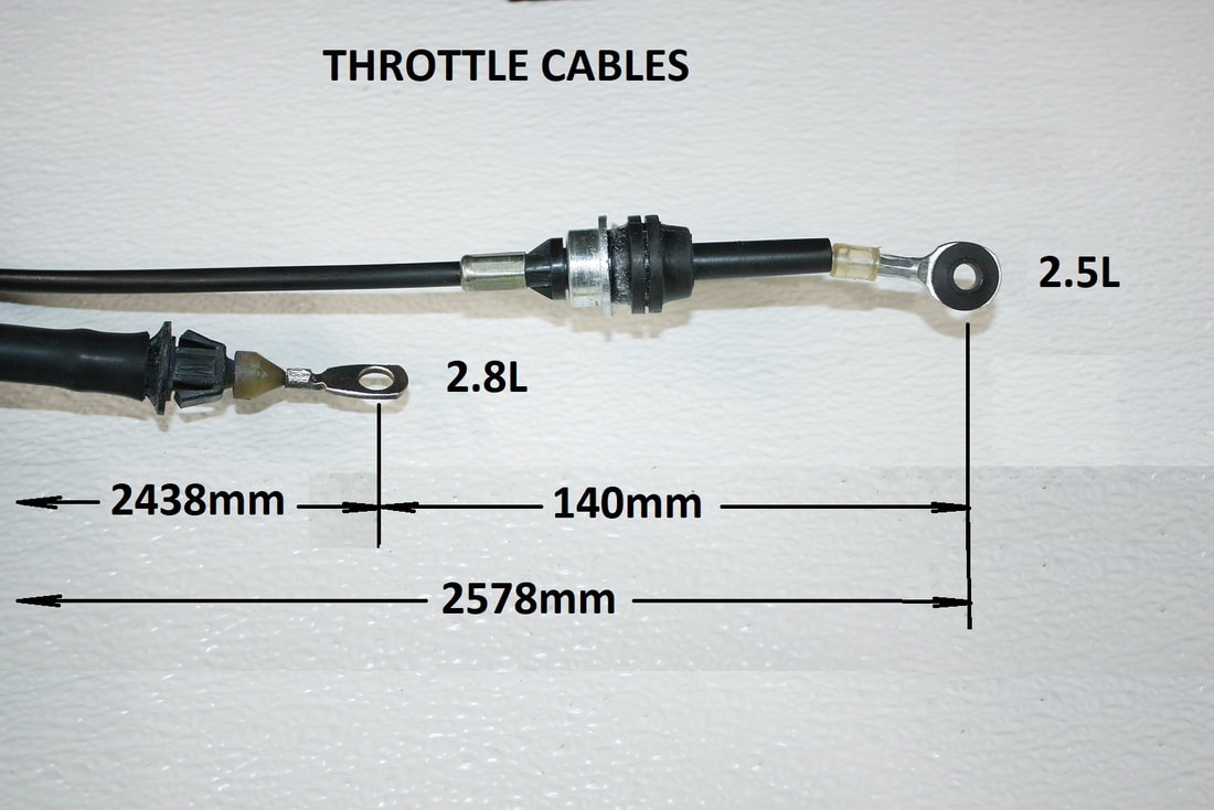
The convenient thing about these units is that the cables are interchangeable between cars allowing you to select the one with the best length for your application. I lucked-in with the stock Northstar cable being just the right length for where I wanted to install the servo:
The convenient thing about these units is that the cables are interchangeable between cars allowing you to select the one with the best length for your application. I lucked-in with the stock Northstar cable being just the right length for where I wanted to install the servo:
The servo is a bit bulky and heavy, so I would’ve wanted to install it against the firewall, but it also has a plastic cover so I was afraid the heat from the headers might affect it there. So I settled on hiding it under the air filter box.
The first step in mounting it there was to figure out a suitable mounting bracket. The Cadillac bracket wasn’t any good as-is, but it had rubber isolators to prevent the vibrations of the spinning motor from being transmitted to the chassis:
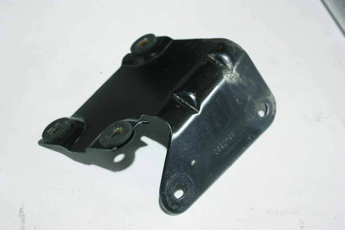
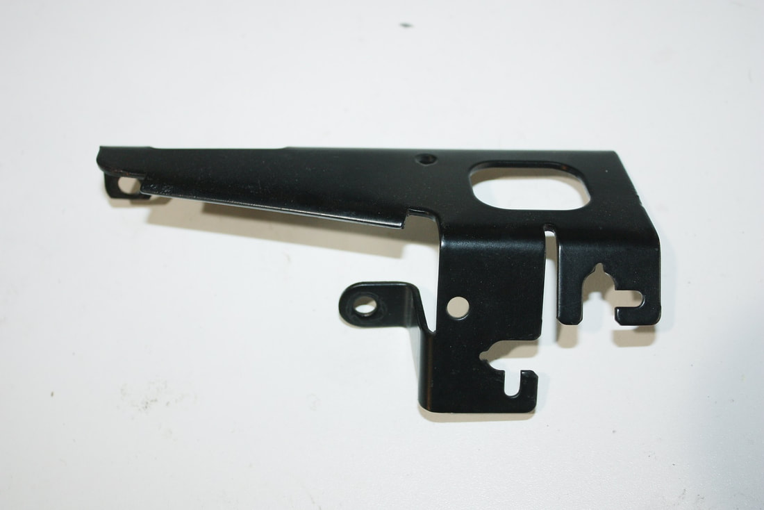
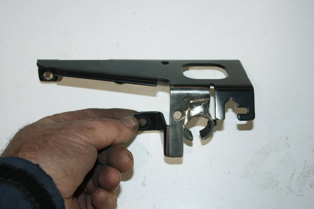
I chopped the side of the bracket off, then welded a little angle bracket to one end to counter the slope of the lower frame rail:
I chopped the side of the bracket off, then welded a little angle bracket to one end to counter the slope of the lower frame rail:
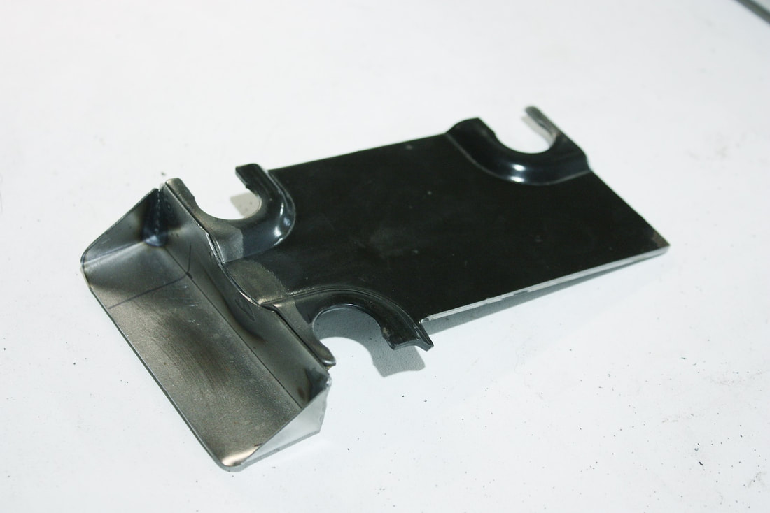
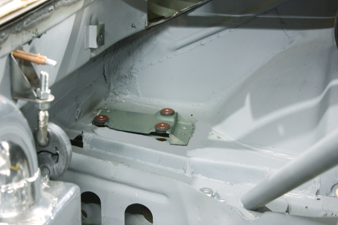
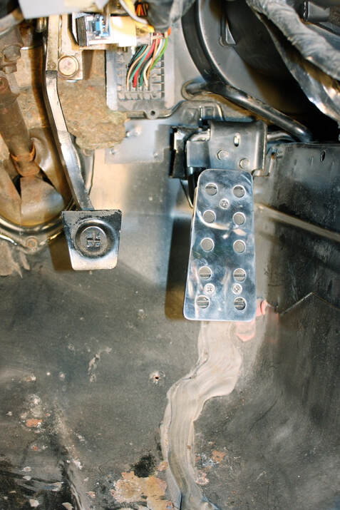
Once it was primed, I positioned the bracket in place, marked the locations of the three servo mounting bolts on the sheet metal below it, and drilled three 5/8” holes in the chassis sheet metal. These holes would allow me to reach up through the bottom with a socket wrench to tighten the servo to the bracket. Then I welded the bracket to the chassis:
Once it was primed, I positioned the bracket in place, marked the locations of the three servo mounting bolts on the sheet metal below it, and drilled three 5/8” holes in the chassis sheet metal. These holes would allow me to reach up through the bottom with a socket wrench to tighten the servo to the bracket. Then I welded the bracket to the chassis:
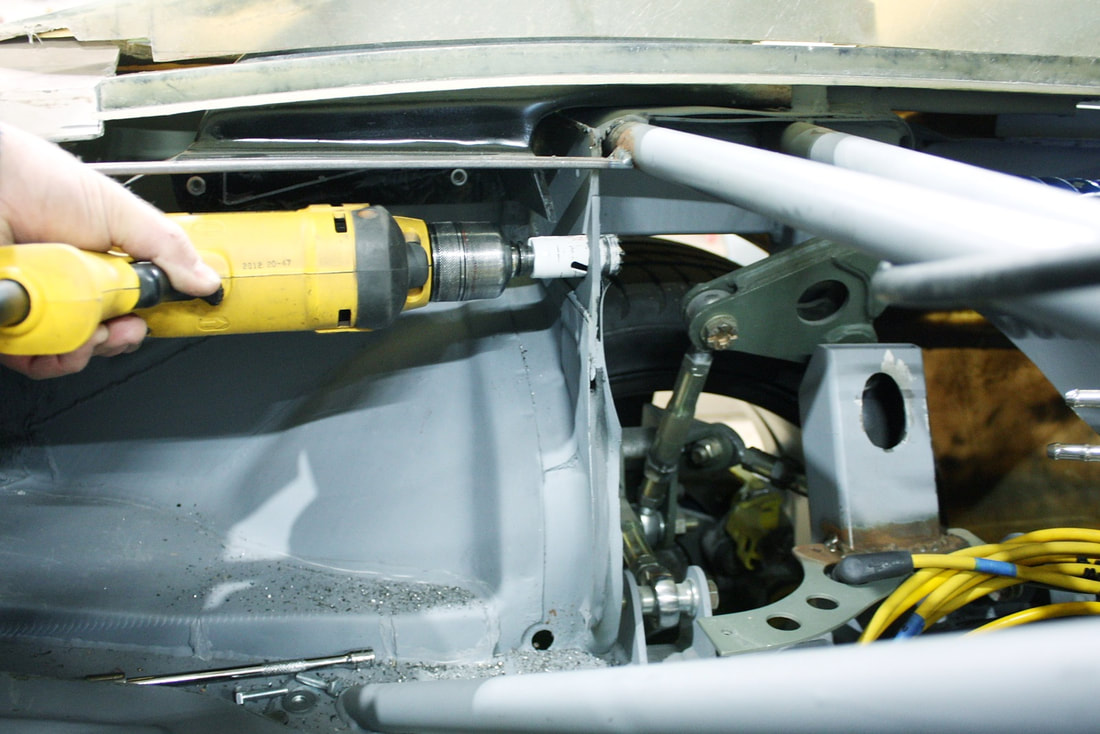
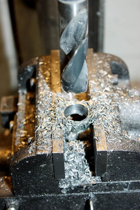
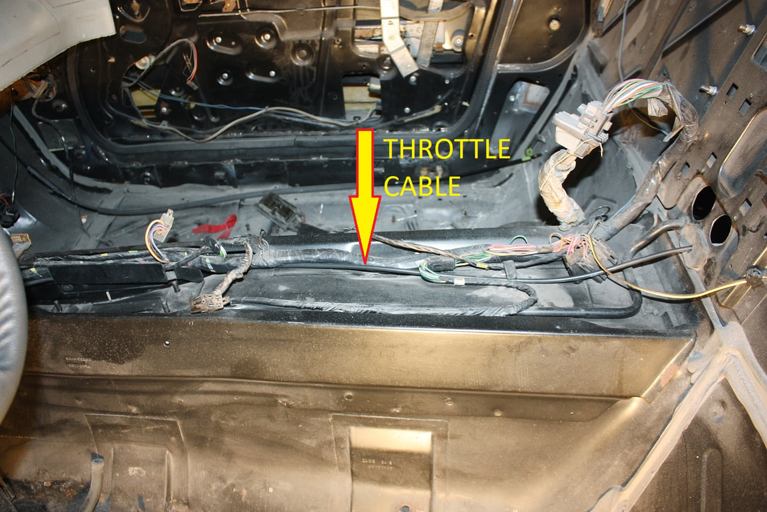
The next step was to drill an access hole in the former strut tower to pass the cruise cable from the trunk area to the engine bay, keeping as much of it hidden under the air filter box as possible:
The next step was to drill an access hole in the former strut tower to pass the cruise cable from the trunk area to the engine bay, keeping as much of it hidden under the air filter box as possible:
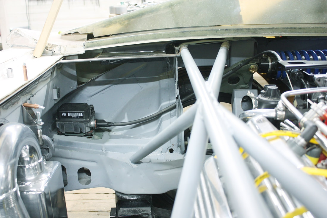
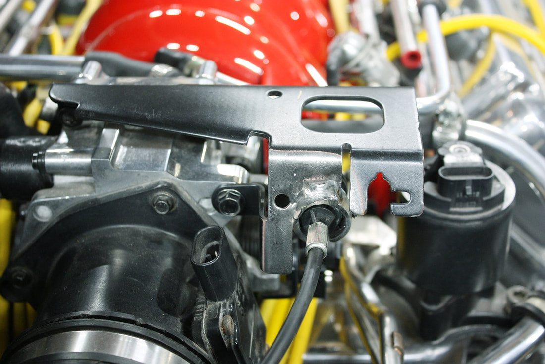
Then I bolted the servo to the bracket and fed the cable through the hole into the engine side of the wall:
Then I bolted the servo to the bracket and fed the cable through the hole into the engine side of the wall:
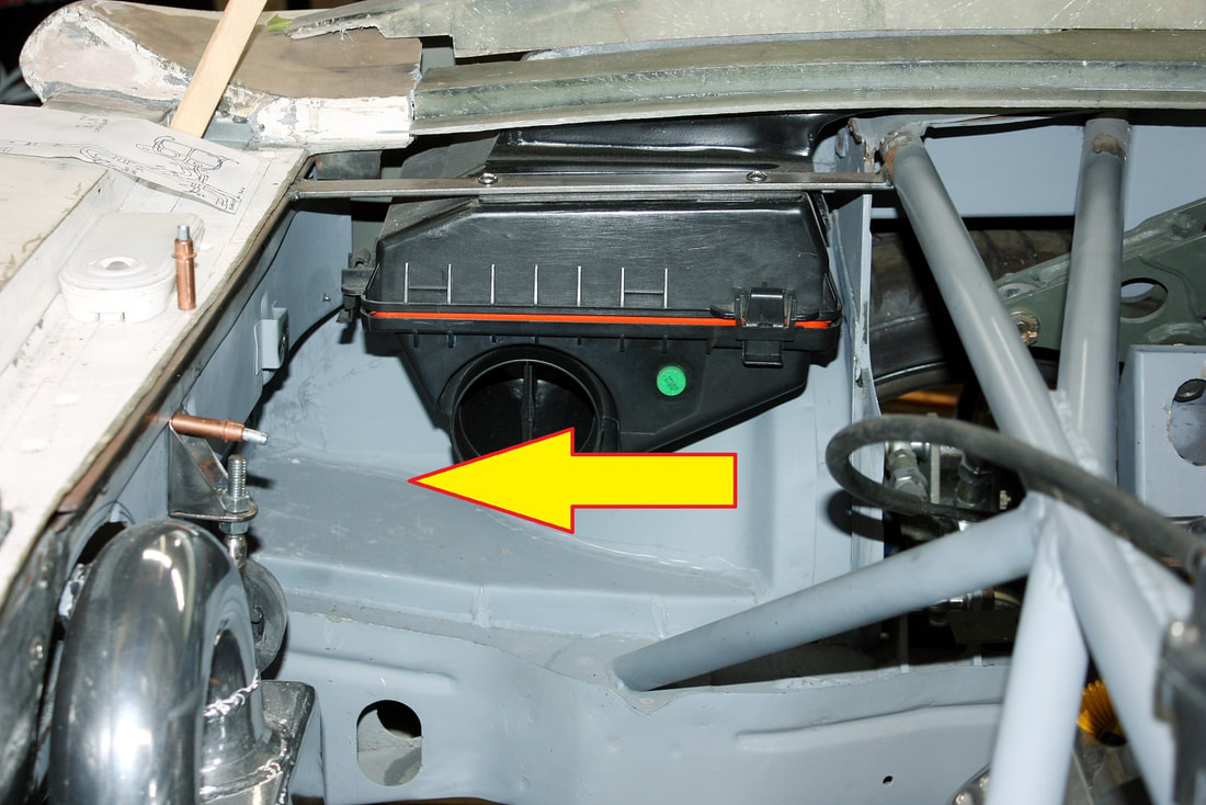
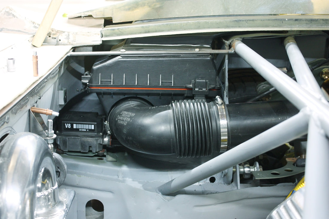
With the servo mounted, I reinstalled the air filter box and ducting to check for fit… perfect!:
With the servo mounted, I reinstalled the air filter box and ducting to check for fit… perfect!:
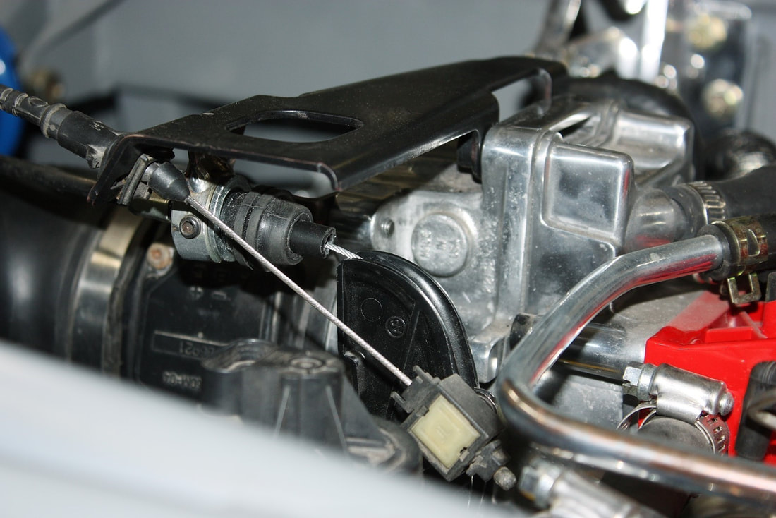
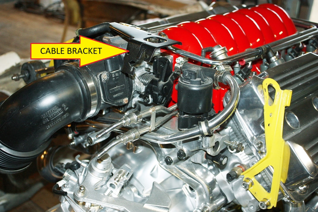
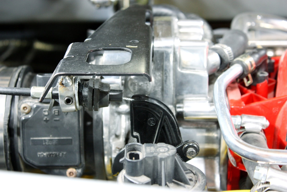
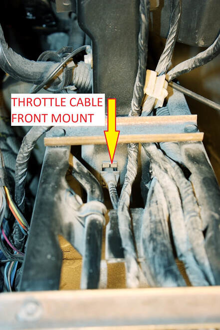
And lastly, I made an easy, large diameter 90 degree curve in the cable toward the throttle body and attached the cable housing to the throttle bracket and cable end to the throttle quadrant. The cruise cable is the one in the foreground here:
And lastly, I made an easy, large diameter 90 degree curve in the cable toward the throttle body and attached the cable housing to the throttle bracket and cable end to the throttle quadrant. The cruise cable is the one in the foreground here:
The electrical connections will come later.
The electrical connections will come later.
 RSS Feed
