Real estate in the engine compartment had already reached a state of near max density when I decided it was time to try and find space for several essential accessories, which until now I had ignored… hoping they would go away. They didn’t.
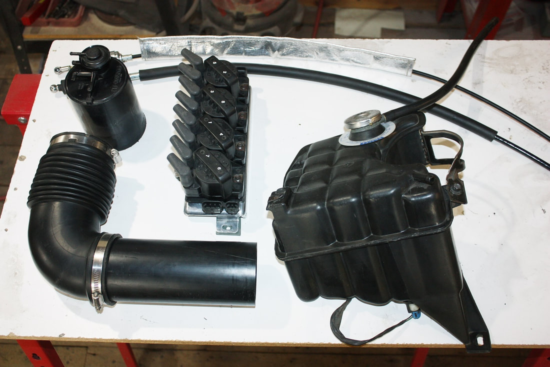
I needed to find space for the gas tank filler tube, charcoal canister, coolant reservoir, throttle cable, shifter cables and mounts, and the ignition coil packs. Here are a few of the parts:
I needed to find space for the gas tank filler tube, charcoal canister, coolant reservoir, throttle cable, shifter cables and mounts, and the ignition coil packs. Here are a few of the parts:
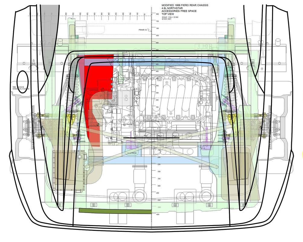
There was free space in the area of the former trunk, but that area was going to get hot with the exhaust system surrounding it, and besides, anything installed there would obstruct the view of the engine and headers which I rathered not do. So the only real “free-space” for all of this stuff was on top of the transmission in the red-shaded area in this top view of the engine bay:
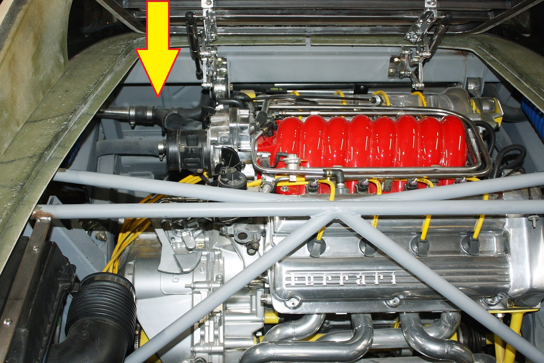
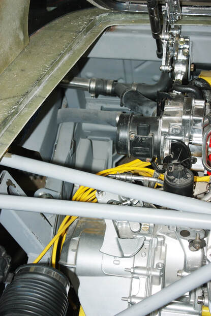
Here are a couple photos of the actual space with the cold air intake tubes removed:
Normal people would focus on installing the stuff that absolutely had to go in this space first, like the shifter and throttle cables, and the gas filler tube, and then any leftover space could be allocated to the stuff that could be placed anywhere (coil packs, vapor canister, and reservoir). But I really, really wanted to hide the coil packs since they’re UG-ly.
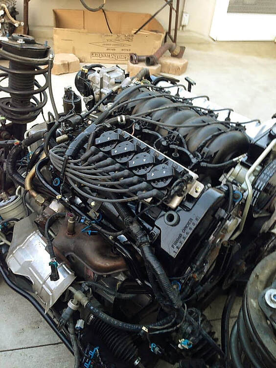
On the Cadillac, the coil packs are mounted on the rear valve cover, where even the folks at GM had the good sense to hide them. However in the Fiero, the rear valve cover becomes the one seen the most, so mounting them in the stock location simply wasn’t going to cut it for me. Here’s a stock engine with the coil packs on the valve cover:
Once removed from the valve cover and stripped of all the wires, the coil pack looks like this:
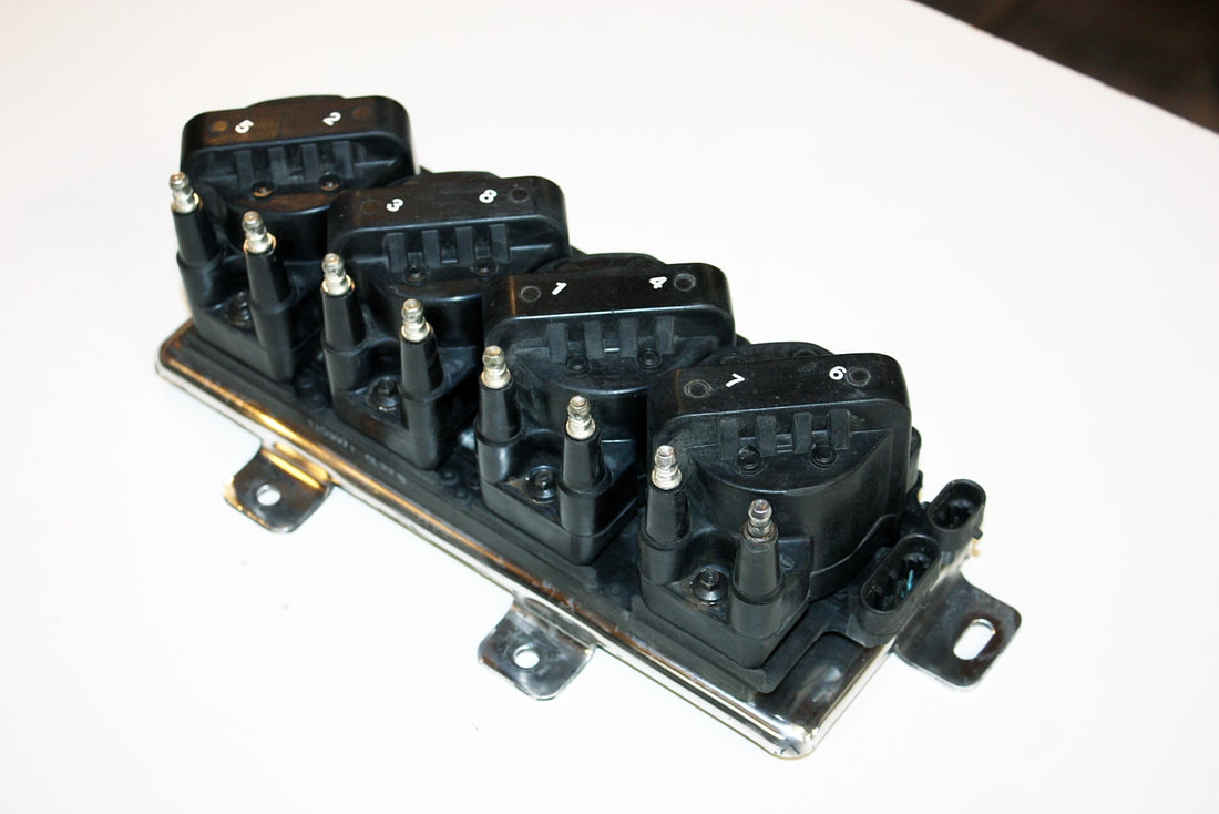
I removed the individual coils from the aluminum base plate/heat sink, cleaned up the corrosion under the packs, polished the aluminum, and remounted the coils onto the base.
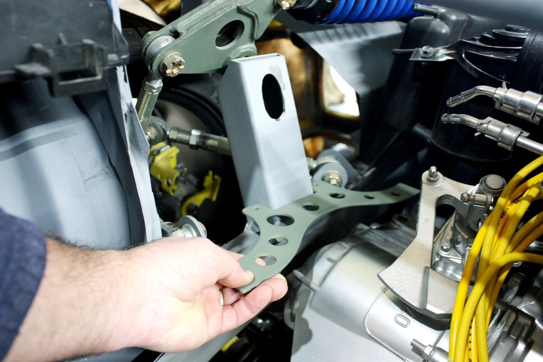
I struggled to find a good spot for the coi: not too close to the exhaust system; as far forward as possible for weight distribution (they’re heavy!); on a solid metal structure (did I mention they’re heavy?); and where they wouldn’t be seen (they’re ugly). I settled on mounting them on the driver’s side bell crank mount, under the cold air intake tube.
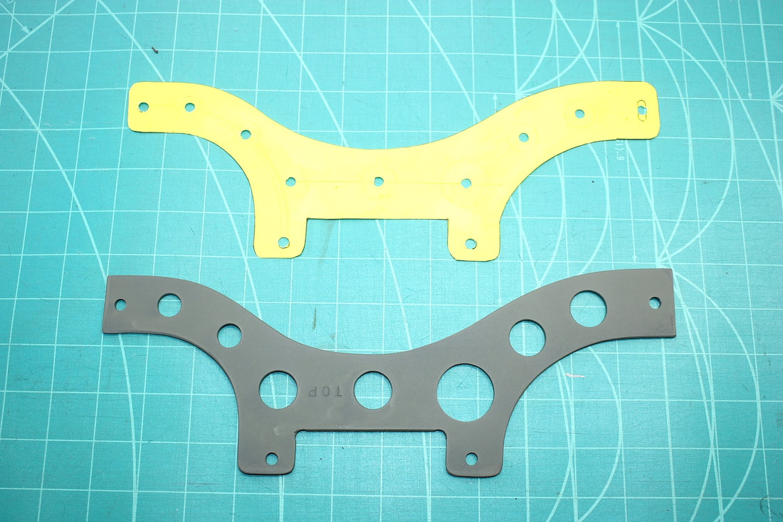
Then I made a cardboard template, followed by a steel mounting bracket, and lightened it with lightening holes:
I made sure there would be clearance below the coil packs to tighten the suspension attaching hardware, and beside it for the shifter cables to work through their arcs of movement, and welded the mounting bracket to the bell crank support:
I made sure there would be clearance below the coil packs to tighten the suspension attaching hardware, and beside it for the shifter cables to work through their arcs of movement, and welded the mounting bracket to the bell crank support:
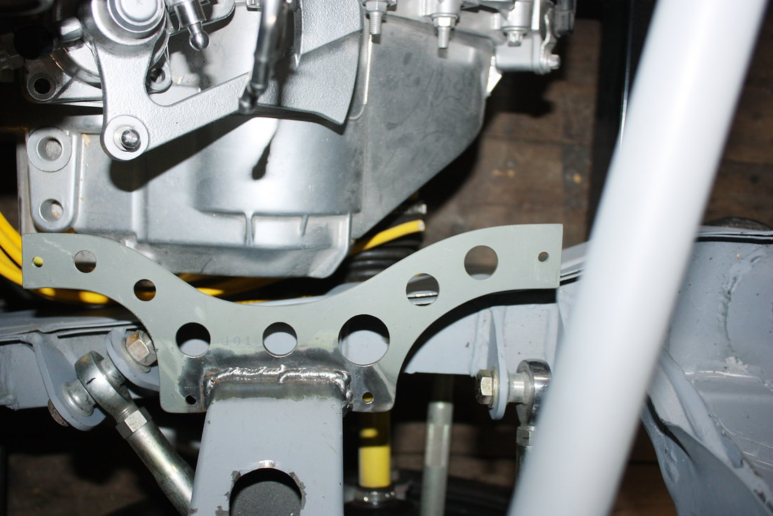
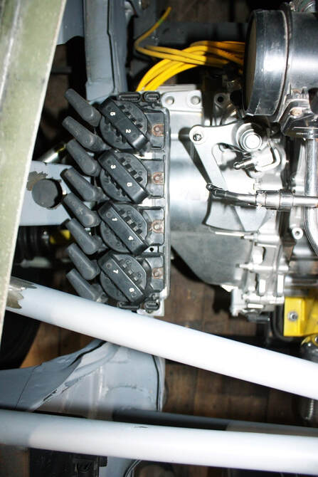
I’ll add some additional braces at either end extending down to the lower frame rail to triangulate it, but otherwise it was done. Next, I bolted the coil pack to the mount and cycled the transmission levers to be certain there was no interference:
With the coil pack mounted, I could finally determine the length required of each spark plug wire and make new ones to fit. At first, I thought of ordering a custom length set from Magnecore, a spark plug wire specialist company, but turned my nose up at the CDN$250 before-shipping-price-tag. So I turned to the stock set I had on hand and decided to modify them. Here’s what the Cadillac wires look like:
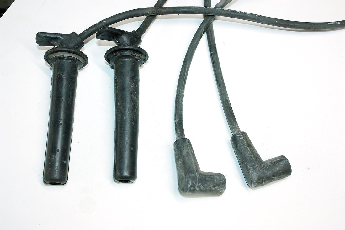
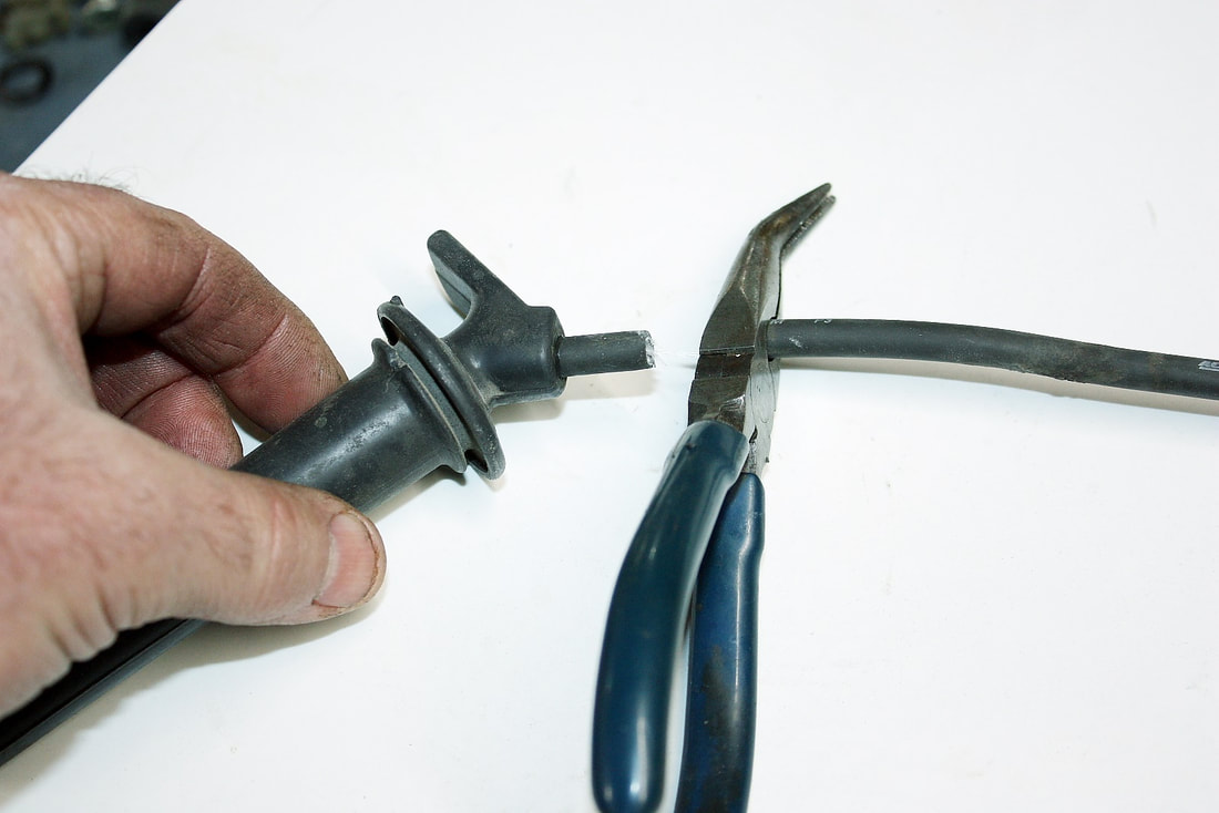
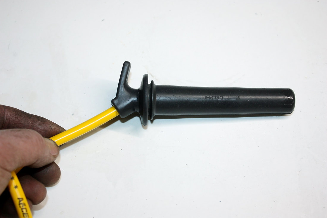
I’d save the unique-to-Cadillac plug boots and graft new wires between them and the more common coil boots. First step: cut off the stock 7mm wires:
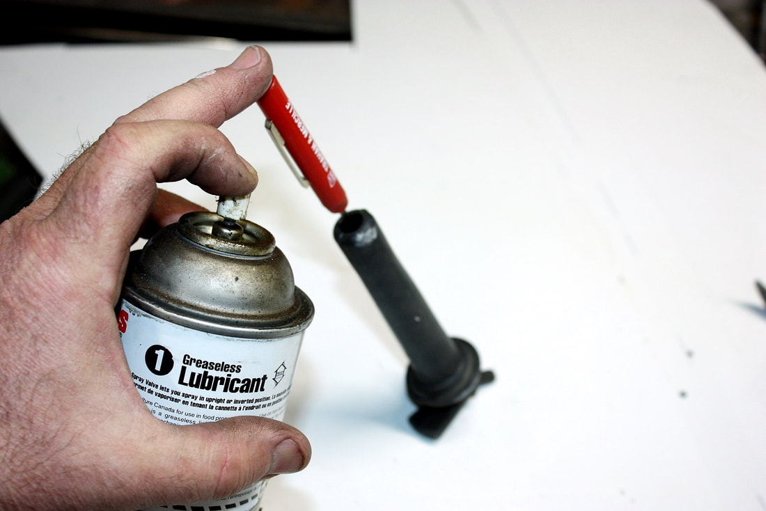
Next up, I needed to pull the metal plug terminals from inside the boots. That proved to be a bit of a challenge since they’re locked solidly in the boots with an integral collar to prevent them from coming apart when servicing the plugs. I had to use a small screwdriver to get enough silicone lubricant between the boot and the metal terminals to get them to release:
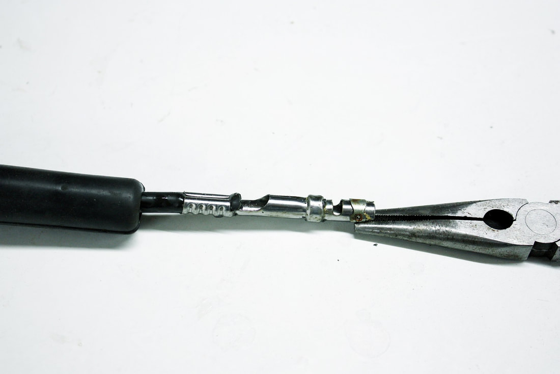
Once the lubricant had a chance to work, the terminals could be pulled out using a pair of needle-nosed pliers and a fair bit of force:
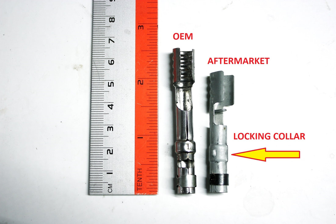
I had hoped to replace the metal terminals, but when new ones arrived, it became clear that they weren’t going to do the job. For starters, they were obviously shorter, but the clincher was that the locking collar was too wide to work properly in the boot:
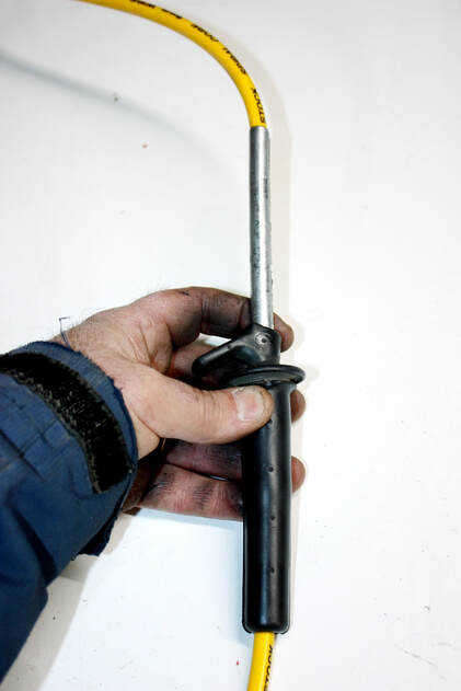
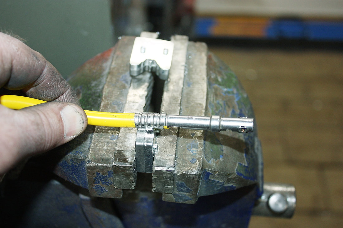
The next challenge was getting an 8mm wire threaded through the 7mm boot. To make matters worse, the boot has a slight bend in it at the top. The trick was to generously lubricate then thread a length of steel brake line all the way through the boot, stretching open and straightening the path. From there, slipping the wire through the brake line, then pulling it out leaving the wire in place, was simple:
The rest was simple plug wire fabrication. Stripping the insulation to reveal a half inch of the core, folding the core back over onto the insulation, and crimpling the terminal over both:
With all the silicone lubricant still present, it was a cinch to seat the terminal in the boot by pulling on the opposite end of the wire. It made a definite “click” as the locking collar found its home in the boot:
After connecting the spark plug ends into the valve covers, and routing each wire along the path I wanted them to follow, I trimmed each wire to length, crimped on the coil terminals, and plugged them in:
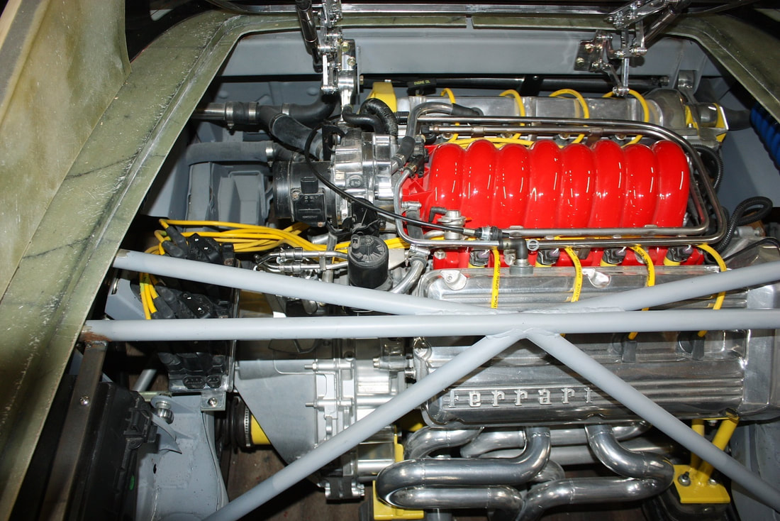
I still had to organize the wires using some sort of wire separators under the throttle body, but remember, this will mostly be hidden under the CAI ducting.
Before the free-space gets any smaller, the next step is to figure out how to shift the transmission.
I still had to organize the wires using some sort of wire separators under the throttle body, but remember, this will mostly be hidden under the CAI ducting.
Before the free-space gets any smaller, the next step is to figure out how to shift the transmission.
 RSS Feed
