**WARNING: This post contains lots of technical discussion.**
There. You’ve been warned. Continue reading at your own peril.
The next thing on my list of “odds & sods” priorities was to devise a way to shift gears in the transmission. A rather important detail. Connecting a cable-actuated Fiero shifter to an F40 transmission is by no means ground-breaking, though I’m not sure anyone has done this with an F40 mounted to a Northstar yet.
Paul Smith (Fieroguru on PFF) worked out the kinematics involved several years ago with an F40 mounted to an LS 4 engine, and devised a slick solution for getting either a stock 5 speed or 4 speed in-car shifter mechanism to work with the F40. He currently markets the parts through his business Fieroguru Performance LLC.
I decided to work out my own solution (with help from Paul, hence the plug for his business :-) ) since my chassis is stretched 3” longer, and the rear-mounted water pump and coolant log on the Northstar is very different from the much “cleaner” back end of an LS engine. Also, unlike Paul, I wanted to see if a Ferrari-style gated shifter could be designed to work with the F40, both for looks and to solve the ambiguity of selecting the middle gates.
I broke the work down into the four following steps to determine where the shifter cables would have to be mounted to make it all work:
I’ll deal with the in-car shifter in another post because you’ll soon see this one will be an overdose of tech as it is.
There. You’ve been warned. Continue reading at your own peril.
The next thing on my list of “odds & sods” priorities was to devise a way to shift gears in the transmission. A rather important detail. Connecting a cable-actuated Fiero shifter to an F40 transmission is by no means ground-breaking, though I’m not sure anyone has done this with an F40 mounted to a Northstar yet.
Paul Smith (Fieroguru on PFF) worked out the kinematics involved several years ago with an F40 mounted to an LS 4 engine, and devised a slick solution for getting either a stock 5 speed or 4 speed in-car shifter mechanism to work with the F40. He currently markets the parts through his business Fieroguru Performance LLC.
I decided to work out my own solution (with help from Paul, hence the plug for his business :-) ) since my chassis is stretched 3” longer, and the rear-mounted water pump and coolant log on the Northstar is very different from the much “cleaner” back end of an LS engine. Also, unlike Paul, I wanted to see if a Ferrari-style gated shifter could be designed to work with the F40, both for looks and to solve the ambiguity of selecting the middle gates.
I broke the work down into the four following steps to determine where the shifter cables would have to be mounted to make it all work:
- measure the operating ranges of the transmission levers;
- measure the suitability of the cable lengths:
- measure the travel ranges of the cables; and
- determine the cable mount locations in relation to the transmission levers.
I’ll deal with the in-car shifter in another post because you’ll soon see this one will be an overdose of tech as it is.
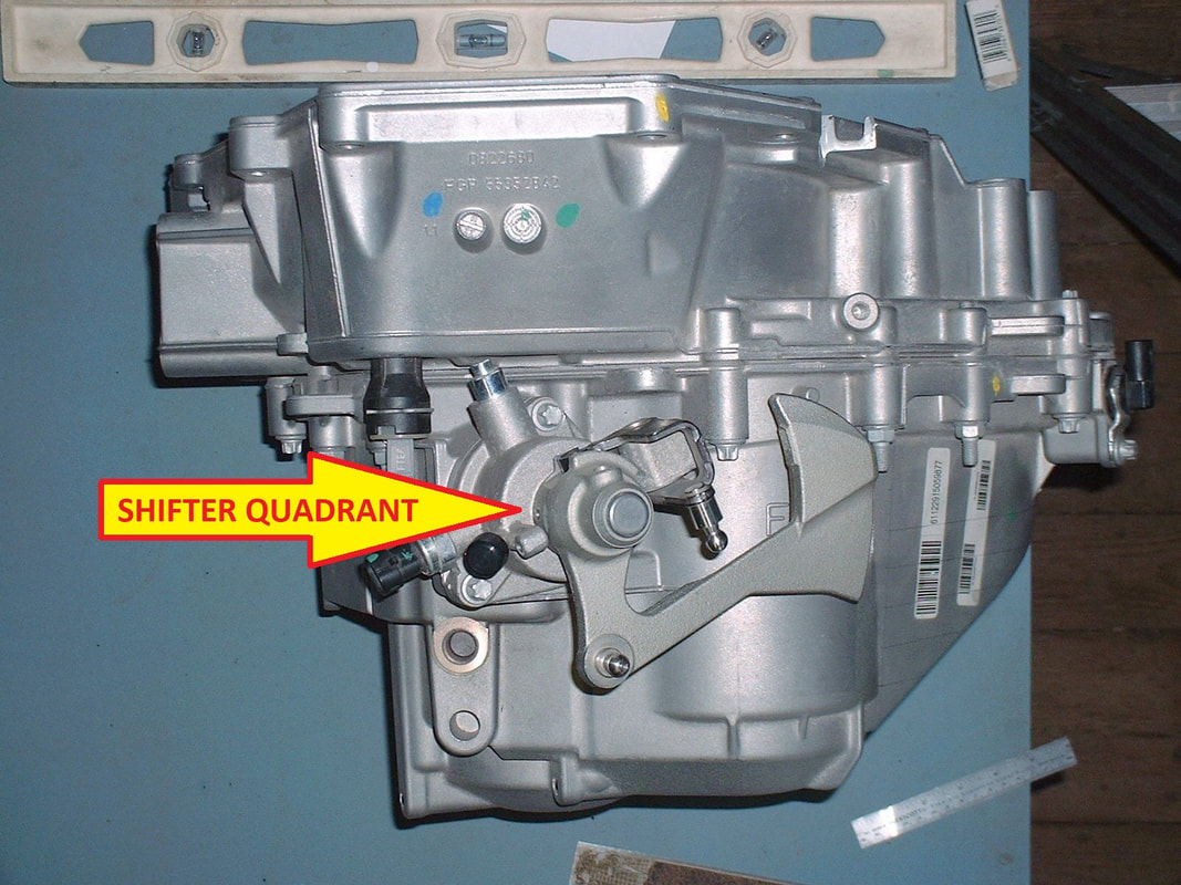
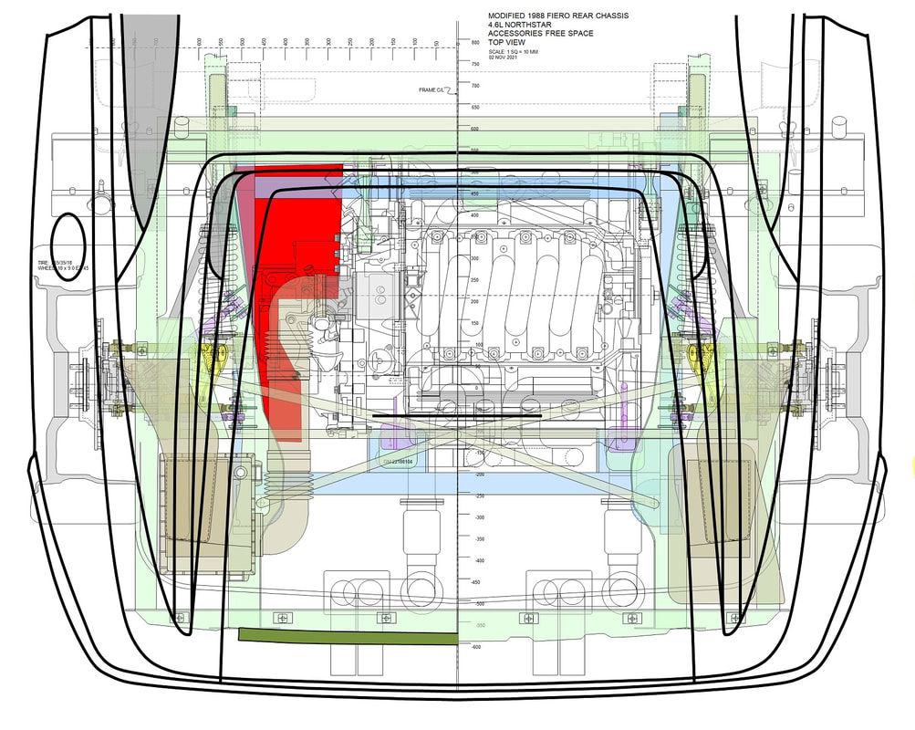
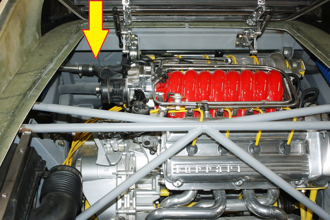
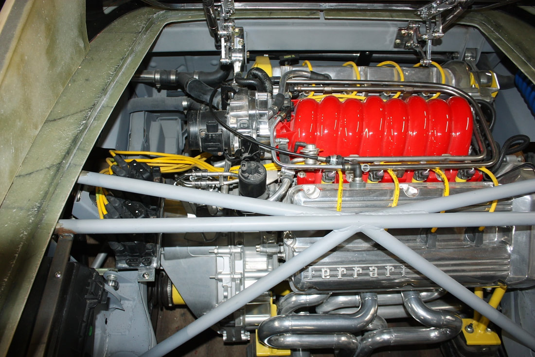
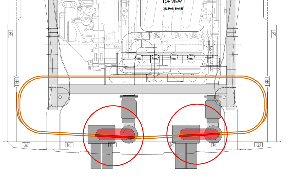
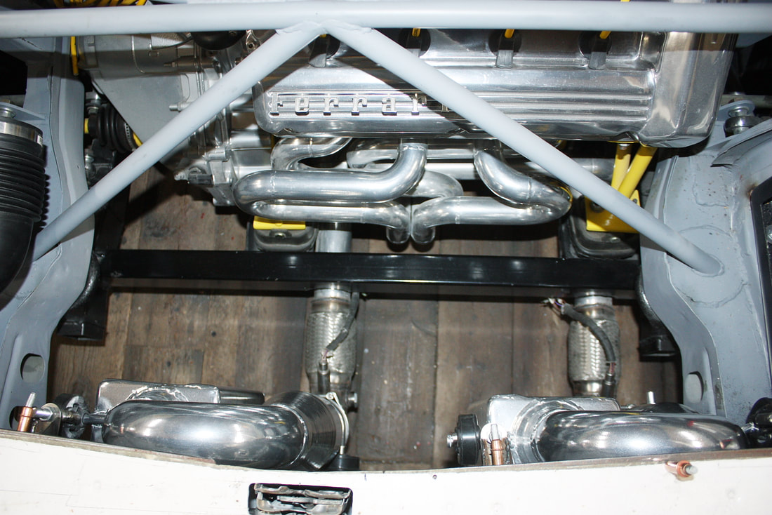
To set the stage for step 1 here’s a top view photo of the F40 showing the gear shift quadrant:
To set the stage for step 1 here’s a top view photo of the F40 showing the gear shift quadrant:
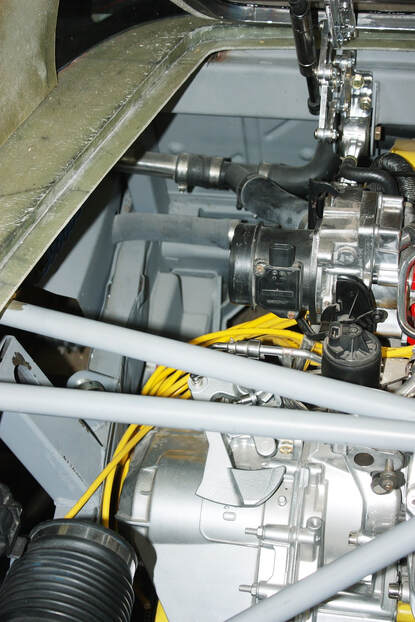
And here’s a close up of the two levers that make up the quadrant, note the ball sockets where the cables attach:
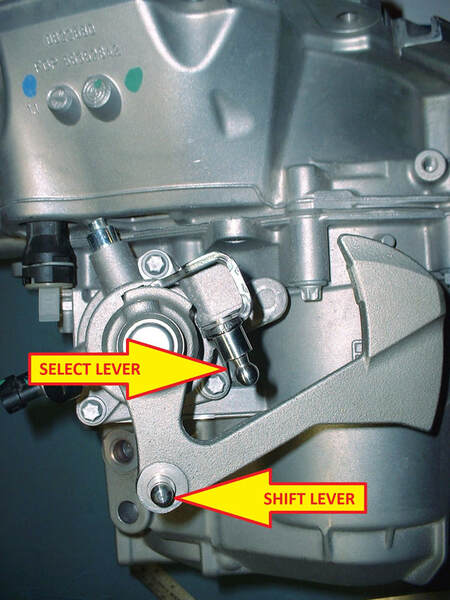
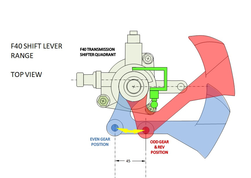
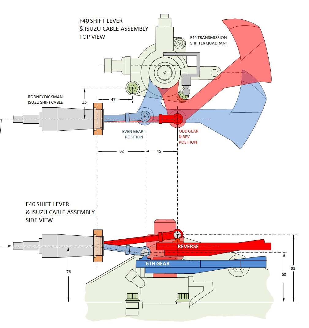
The “Shift Lever” has a long counter-weighted arm attached to it, presumably to give a little inertial help when shifting gears. It rotates between three positions, namely the odd gears, even gears, and neutral. If rotated counter clockwise, it places the transmission in one of the odd numbered gears or reverse gear. This is equivalent to pushing the in-car shift knob forward.
Conversely, if the Shift Lever is rotated clockwise, the transmission ends up in one of the even numbered gears. This is accomplished by pulling the in-car shift knob backwards. On the F40, there are 45 mms of travel at the ball stud when the shift lever is rotated between the even and odd gears.
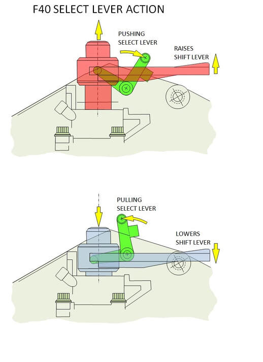
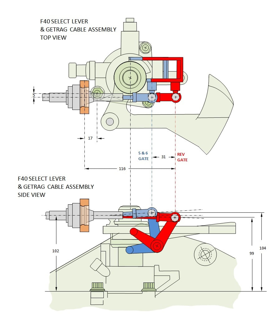
The (green) Select Lever on the other hand is used to choose a gate. A gate is the neutral area in the H-pattern between first and second, or third and fourth, or fifth and sixth gears, or reverse. It does this by changing the height of the shift lever by a prescribed amount.
Moving the in-car shift knob sideways all the way toward the driver, aligning it with the reverse gate on the F40, pushes the green Select lever on the transmission toward the rear of the car (see below, top image), which raises the shift lever (in red) out of the transmission housing.
Conversely, when the in-car shift knob is moved sideways all the way toward the passenger, the Select lever gets pulled toward the front of the car (lower image below), pushing the shift lever deeper into the transmission, aligning it with the 5-6 gate. These are the two extreme movements of the select lever, but there are also two intermediate locations that correspond with the 1-2 gate or the 3-4 gate. Confused yet?:
The full range of travel of the Select lever is 31mms back and forth as shown below.
The full range of travel of the Select lever is 31mms back and forth as shown below.
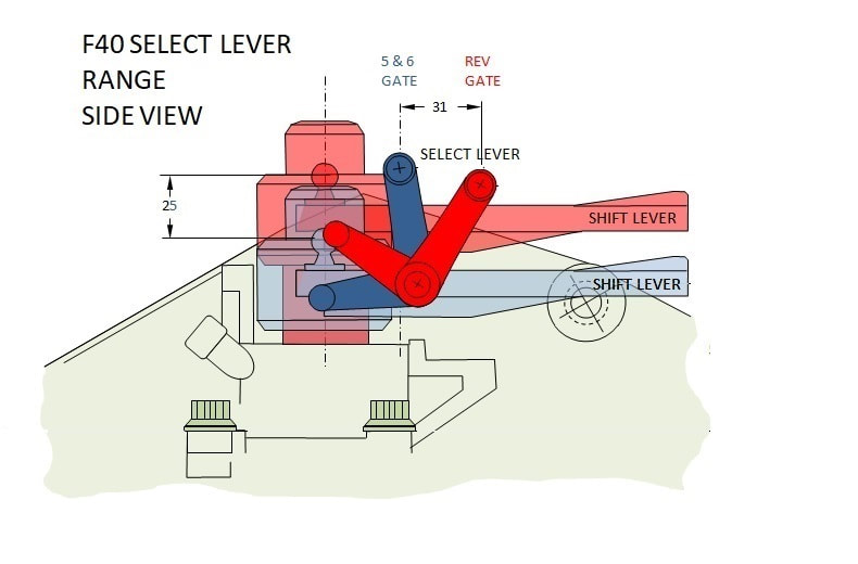
Also shown above, when the Select lever is moved between its lower and upper limit, it causes the Shift lever to raise out of the transmission 25mms. The fact that the shift cable must be able to accommodate a push/pull motion as well as an up/down deflection is an important consideration.
So, with the functions and ranges of the transmission levers defined, the next step was to see whether the stock Fiero cables were up to the task.
STEP 2: Overall Length of the Cables
An often-asked question is why not simply use the Pontiac G6 transmission cables with the F40 transmission. The reason is because they're too short. The G6 is a front-engine car with significantly shorter cables running from the shifter to the transmission. In fact, nearly every other car except very expensive exotics have much shorter cables than the stock Fiero because of the mid engine configuration.
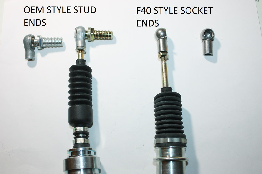
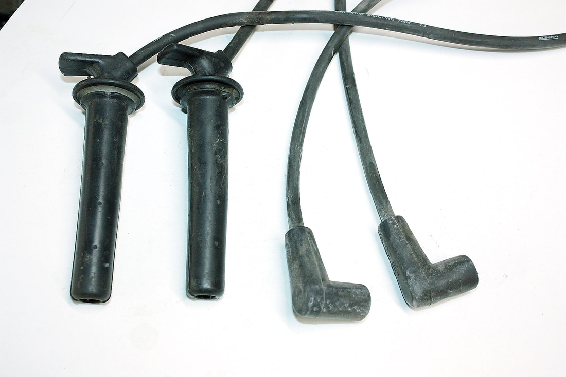
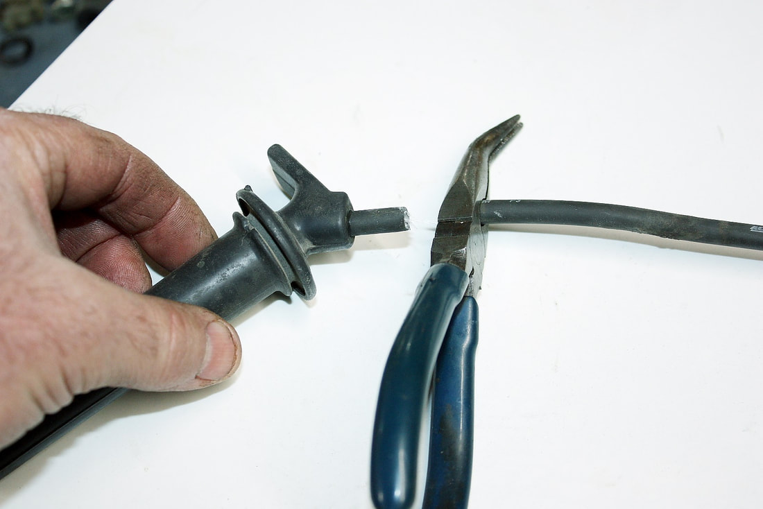
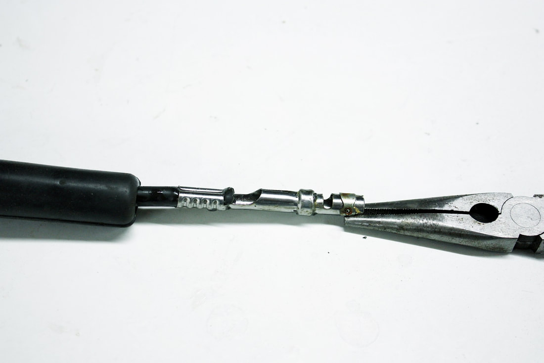
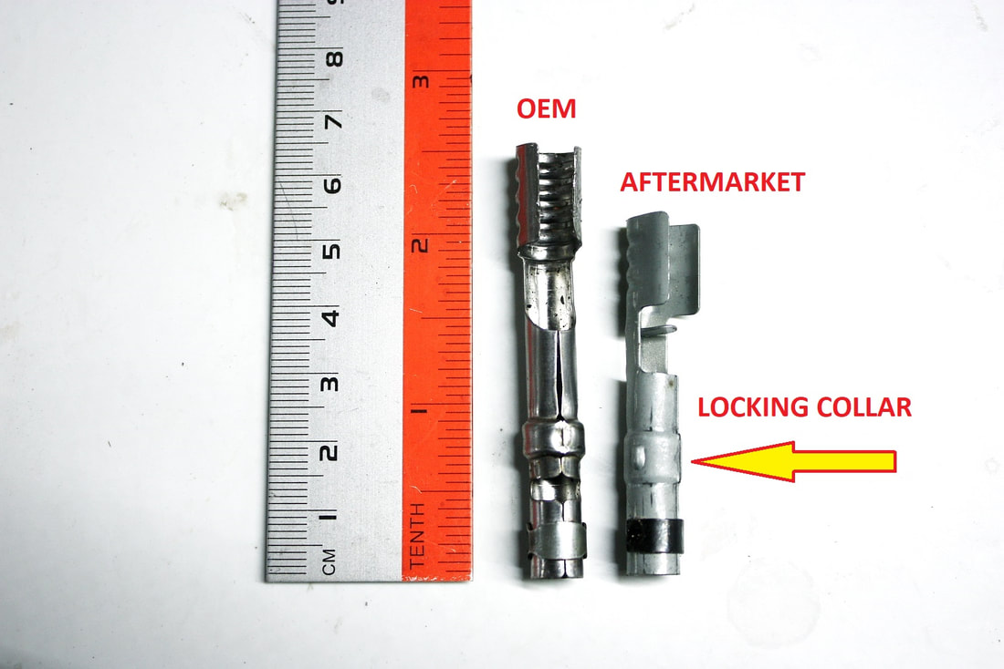
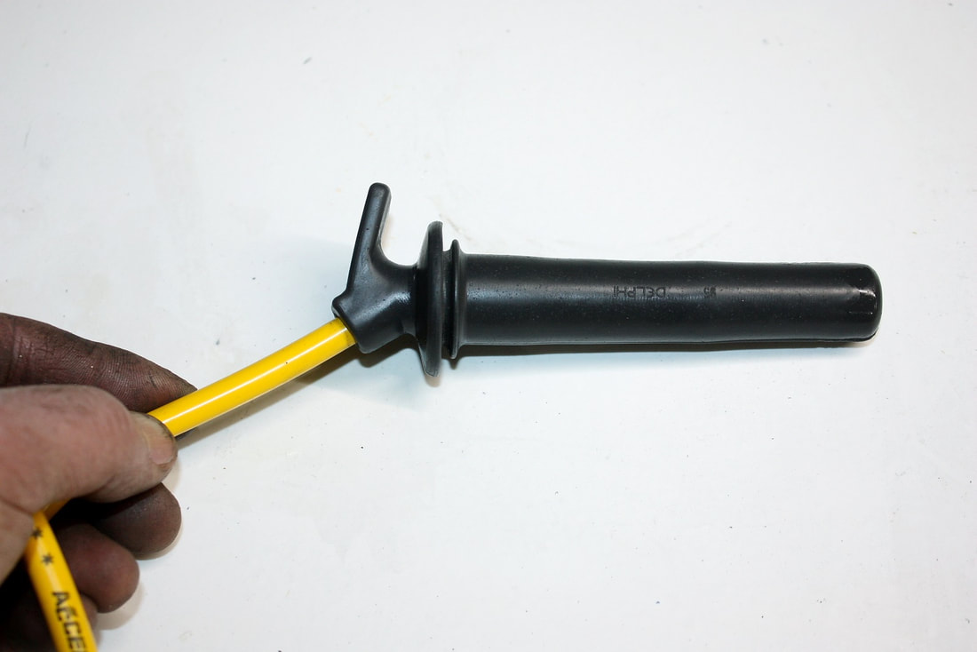
That leaves Fiero cables or custom cables as the only two choices. But even then, not all Fiero cables are created equal. There were four different manual transmissions offered, each with their own unique cable lengths and attaching hardware. Fieroguru determined that a Fiero Isuzu shift cable in combination with a Fiero Getrag select cable resulted in the best matched set, lengthwise, for use with the F40 transmission on an un-stretched chassis. The only problem then was to modify the transmission ends for the F40 ball sockets. Rodney Dickman (RD), a Fiero aftermarket parts developer and supplier, came to the rescue with cables that had interchangeable ends and the correct ball sockets:
Also shown above, when the Select lever is moved between its lower and upper limit, it causes the Shift lever to raise out of the transmission 25mms. The fact that the shift cable must be able to accommodate a push/pull motion as well as an up/down deflection is an important consideration.
So, with the functions and ranges of the transmission levers defined, the next step was to see whether the stock Fiero cables were up to the task.
STEP 2: Overall Length of the Cables
An often-asked question is why not simply use the Pontiac G6 transmission cables with the F40 transmission. The reason is because they're too short. The G6 is a front-engine car with significantly shorter cables running from the shifter to the transmission. In fact, nearly every other car except very expensive exotics have much shorter cables than the stock Fiero because of the mid engine configuration.
That leaves Fiero cables or custom cables as the only two choices. But even then, not all Fiero cables are created equal. There were four different manual transmissions offered, each with their own unique cable lengths and attaching hardware. Fieroguru determined that a Fiero Isuzu shift cable in combination with a Fiero Getrag select cable resulted in the best matched set, lengthwise, for use with the F40 transmission on an un-stretched chassis. The only problem then was to modify the transmission ends for the F40 ball sockets. Rodney Dickman (RD), a Fiero aftermarket parts developer and supplier, came to the rescue with cables that had interchangeable ends and the correct ball sockets:
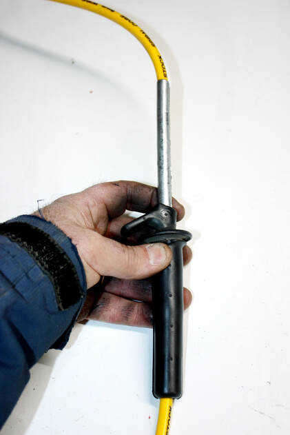
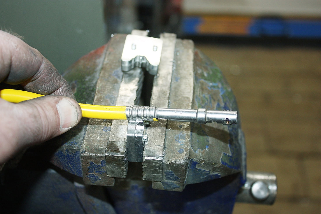
I bought a pair of Rodney’s cables and mocked them up in my stretched chassis and was relieved when I discovered they were easily long enough to bridge the extra distance between the shifter and the transmission, given my stretched chassis.
STEP 3: Travel Ranges of the Cables
Next up was to measure the total travel and maximum deflection of each cable end. Here’s a pair of drawings showing the key dimensions of both cables as well as a comparison between the OEM and RD cables since there are some differences:
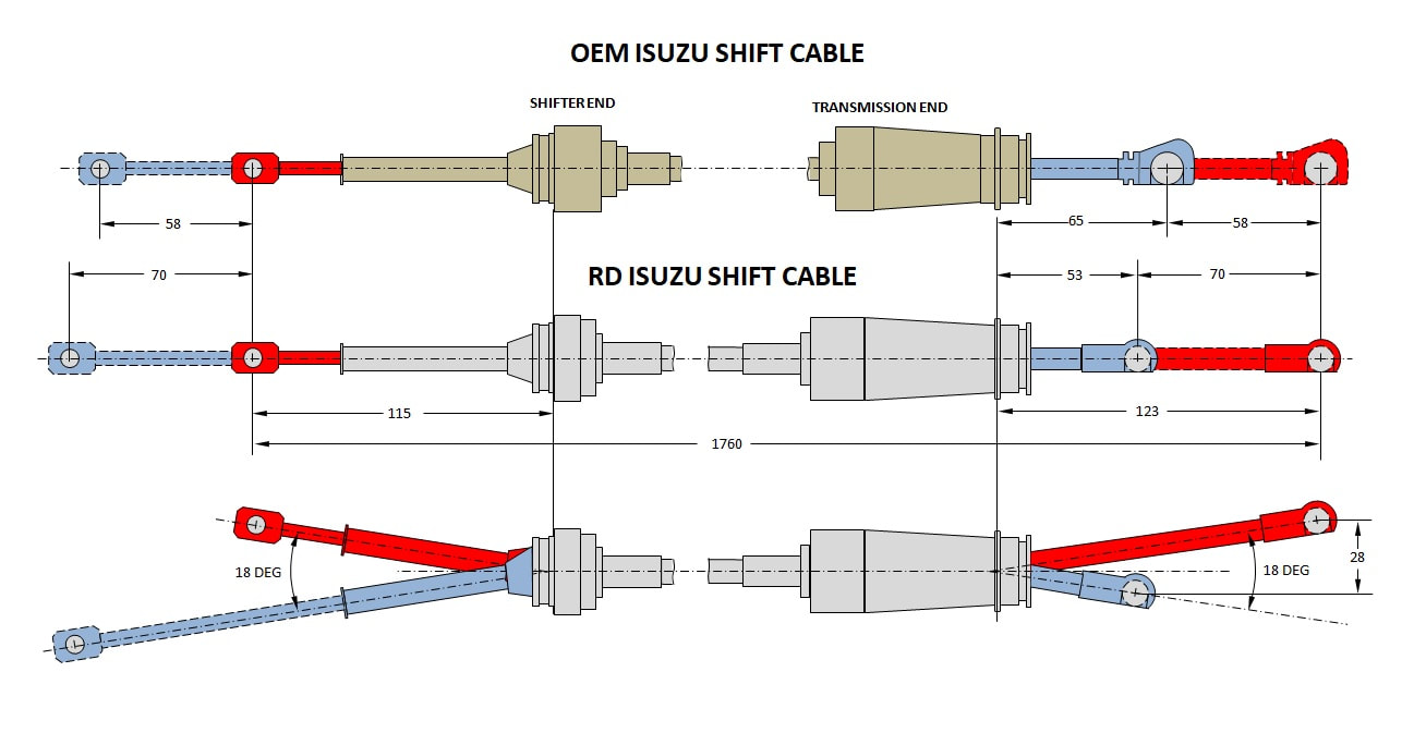
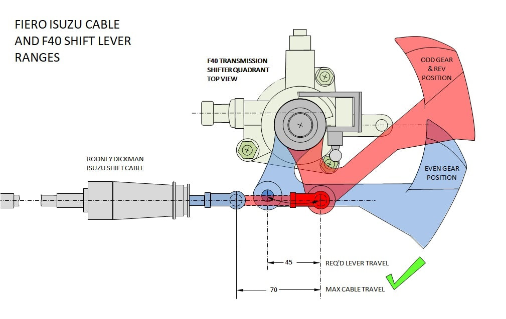
With the specs of both cables, it was easy to see whether they had the minimum travel and deflection ranges to operate the F40 levers without binding. I checked the tolerances by combining my different drawings together.
This next drawing shows that the Isuzu shift cable has a maximum travel of 70 mm, whereas the shift lever only requires 45 mm for full range. In this view, the cable is obviously capable of exceeding the transmission lever’s throw (green check mark):
But since the shift lever also moves vertically, the cable end had to be able to deflect throughout the entire angular range of the ball socket without binding. As measured earlier, the total vertical travel of the shift lever is 25mm. The Isuzu cable is capable of deflecting a maximum of 28mm in the worst case scenario: shortest and lowest throw to longest and highest throw. (see green check mark below):
But since the shift lever also moves vertically, the cable end had to be able to deflect throughout the entire angular range of the ball socket without binding. As measured earlier, the total vertical travel of the shift lever is 25mm. The Isuzu cable is capable of deflecting a maximum of 28mm in the worst case scenario: shortest and lowest throw to longest and highest throw. (see green check mark below):
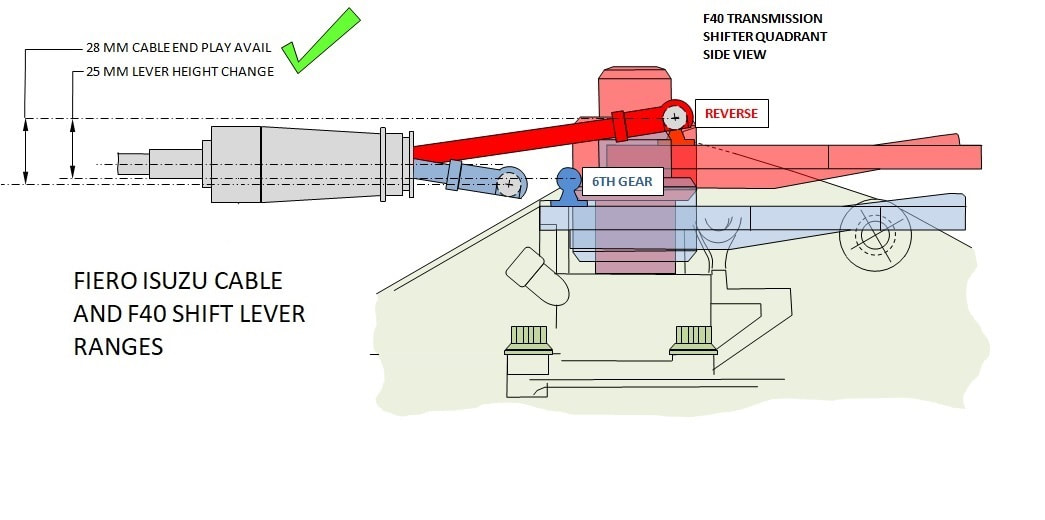
With this narrow 3mm window of vertical tolerance, it’s very important to precisely locate the cable housing vertically in a custom mounting bracket. Without drawings, the correct height of the cable would’ve been nearly impossible to determine.
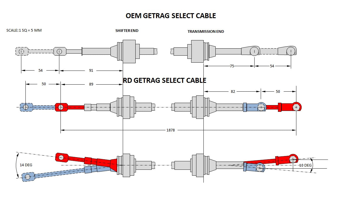
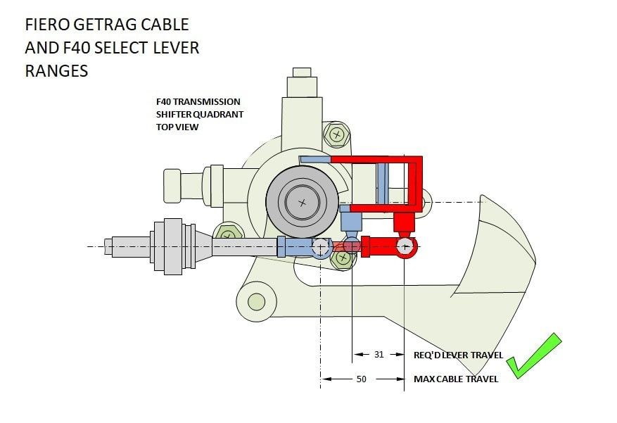
Next up was to check if the Select cable could meet the needs of the select lever. This next drawing shows that the cable is capable of 50mm of travel compared to the lever’s 31mm range. Obviously it would be suitable from a length of travel perspective:
With this narrow 3mm window of vertical tolerance, it’s very important to precisely locate the cable housing vertically in a custom mounting bracket. Without drawings, the correct height of the cable would’ve been nearly impossible to determine.
Next up was to check if the Select cable could meet the needs of the select lever. This next drawing shows that the cable is capable of 50mm of travel compared to the lever’s 31mm range. Obviously it would be suitable from a length of travel perspective:
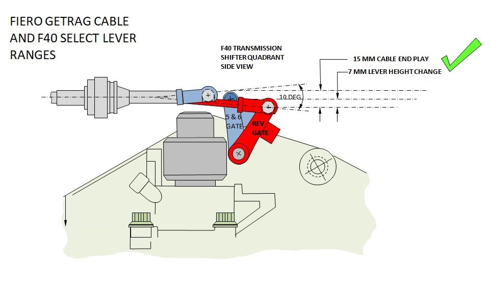
The side view also confirmed that the 7mm vertical travel of the lever easily fell within the maximum 15mm deflection range of the cable end. Placement of the Select cable housing wouldn’t be as critical as the Shift cable housing:
The side view also confirmed that the 7mm vertical travel of the lever easily fell within the maximum 15mm deflection range of the cable end. Placement of the Select cable housing wouldn’t be as critical as the Shift cable housing:
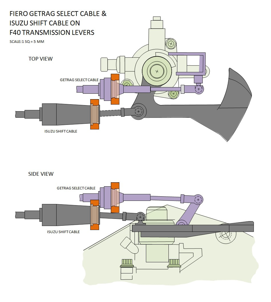
The final step at this end of the cables was to determine the 3D coordinates that each cable housing would have to be mounted to guarantee full operation of the transmission.
STEP 4: Cable Mount Locations
Everything up to this point only confirmed that the two chosen cables, when considered in isolation, had enough length, travel, and flexibility to actuate the transmission levers. The precise XYZ coordinates of the cable mounts were still up in the air, but at least a window of suitability had been determined for each cable.
I could’ve used the locations I depicted in the above drawings, but in every preceding drawing, I arbitrarily attached the cables to the levers at the maximum travel limit of the cable. I could’ve just as easily chosen to attach them at the minimum travel limit instead. In the case of the Select cable, which has 20mm of extra cable travel, that would have resulted in a 20mm longitudinal difference in the location of the cable mount. It doesn’t sound like much, but given the proximity the two cable mounts must be in relation to each other, this could easily have resulted in interference. There were other considerations too.
In the end, my final choice of mount coordinates took into account many factors including: minimizing the angularity of the cables at each extremity of the lever movements; optimizing the cable travel to ensure the in-car shift pattern would be biased toward the driver; and ensuring the location of the two mounts would not interfere with each other, nor interfere with the fabrication of the mount. All this to say the final step was as much art as science.
Here are the coordinates of the Shift cable mount (in orange) in relation to one of the shift quadrant bolts and the Shift lever ball stud for cross reference:
And here are the XYZ coordinates of the Select cable mount in relation to the same shift quadrant bolt and the Select lever ball stud for cross reference:
And here are the XYZ coordinates of the Select cable mount in relation to the same shift quadrant bolt and the Select lever ball stud for cross reference:
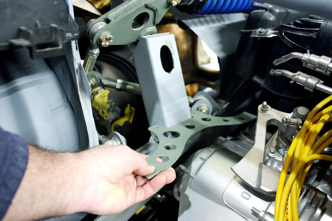
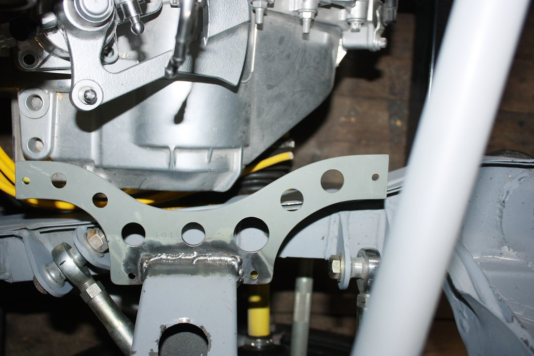
Drawn together, the two mounts end up with enough spatial separation to make a single bracket to hold both. This is the same determination that Paul Smith made for his LS4 powered car. The differences will lie in the shape of the mounting bracket in order to clear different obstacles.
Drawn together, the two mounts end up with enough spatial separation to make a single bracket to hold both. This is the same determination that Paul Smith made for his LS4 powered car. The differences will lie in the shape of the mounting bracket in order to clear different obstacles.
My next post will be about fabricating the bracket needed to hold the cable ends where I calculated they should be.
My next post will be about fabricating the bracket needed to hold the cable ends where I calculated they should be.
 RSS Feed
