Welcome to the part of my blog where I tackle the toughest part of this car: the rear end. Stepping back for a moment to view the photos of the car on the home page will remind you why this is going to be very involved. The original Fiero engine and automatic transmission were still installed, the body sat way too high on the suspension, the wheels sat way too far inboard for a simple change in wheels to fix, and rust had invaded several key frame areas.
I decided early on that a wholesale redesign of the engine sub-frame and suspension would be needed to correct all of these problems. To complicate matters, pending legislation in my Province threatens to curtail hobbyists from modifying suspension systems unless they can be proven to be superior in performance to the stock configuration. This meant double the work load since I would not only have to analyze my own design, but also reverse engineer the stock Fiero suspension to create baseline data for comparison.
The only way I knew how to do this was through simulation software. To feed the data requirements of the software, I would spend about 600 hours accurately measuring and drawing out frame and suspension components to determine their relationship to each other in three dimensions. These drawings would later help me design the new suspension as well.
To gain access to the stock frame attachment points and components, I pulled the Fiero engine sub-frame complete with the stock engine, transmission, and suspension out from under the car:
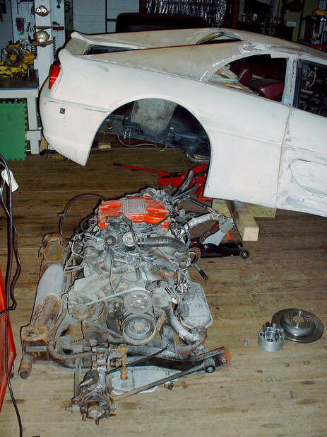
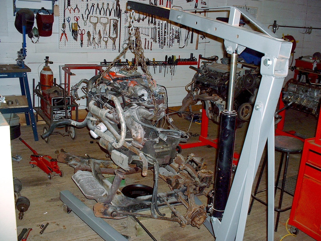
Once the car was raised high enough for the plenum to clear the lower passenger side frame rail, I rolled the engine out from the rear wheel well. Then I separated the engine and transmission from the sub-frame:
Once the car was raised high enough for the plenum to clear the lower passenger side frame rail, I rolled the engine out from the rear wheel well. Then I separated the engine and transmission from the sub-frame:
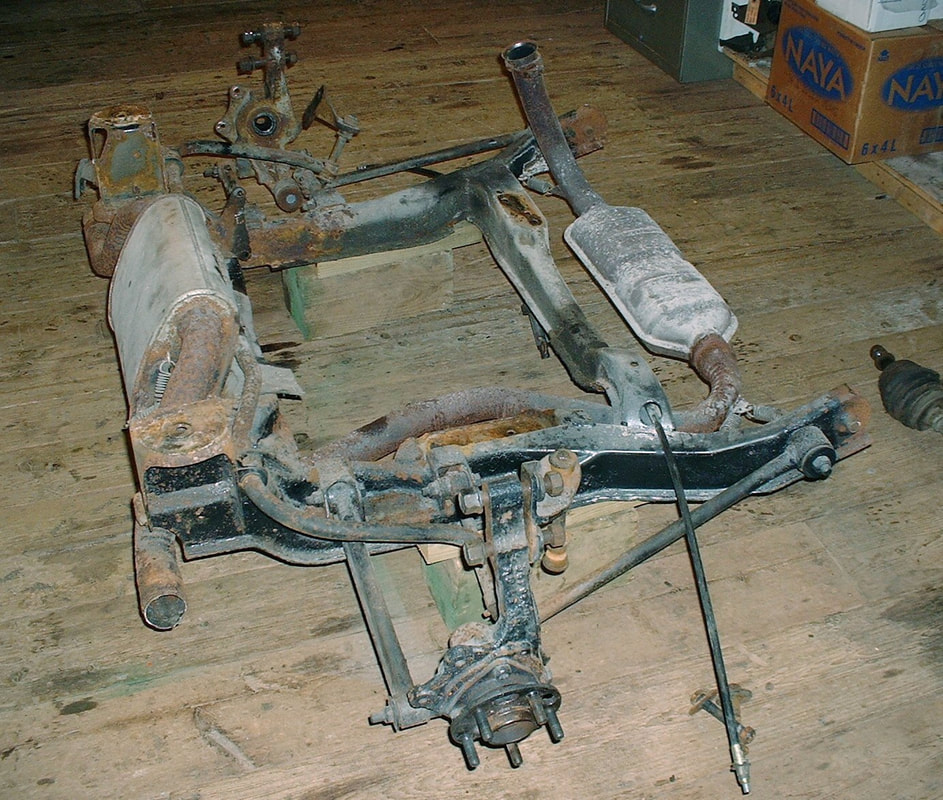
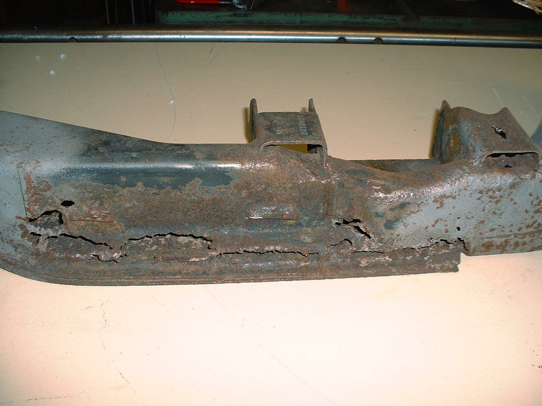
I cleaned it enough to take some decent measurements, but from this series of pictures, you can see it was beyond repair.
I cleaned it enough to take some decent measurements, but from this series of pictures, you can see it was beyond repair.
Perforation rust was evident in all of the structural areas including the side rails:
Perforation rust was evident in all of the structural areas including the side rails:
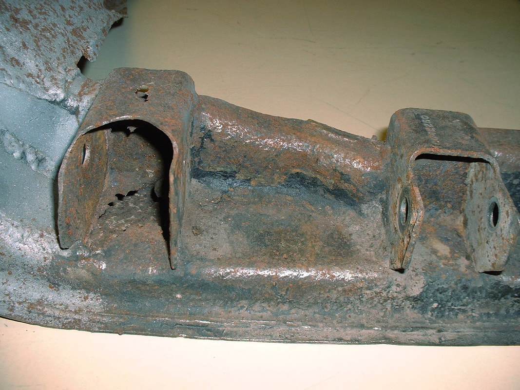
...the suspension mounts:
...the suspension mounts:
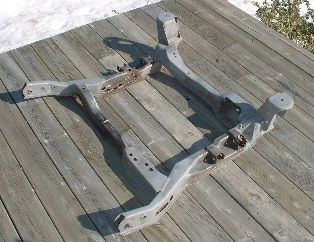
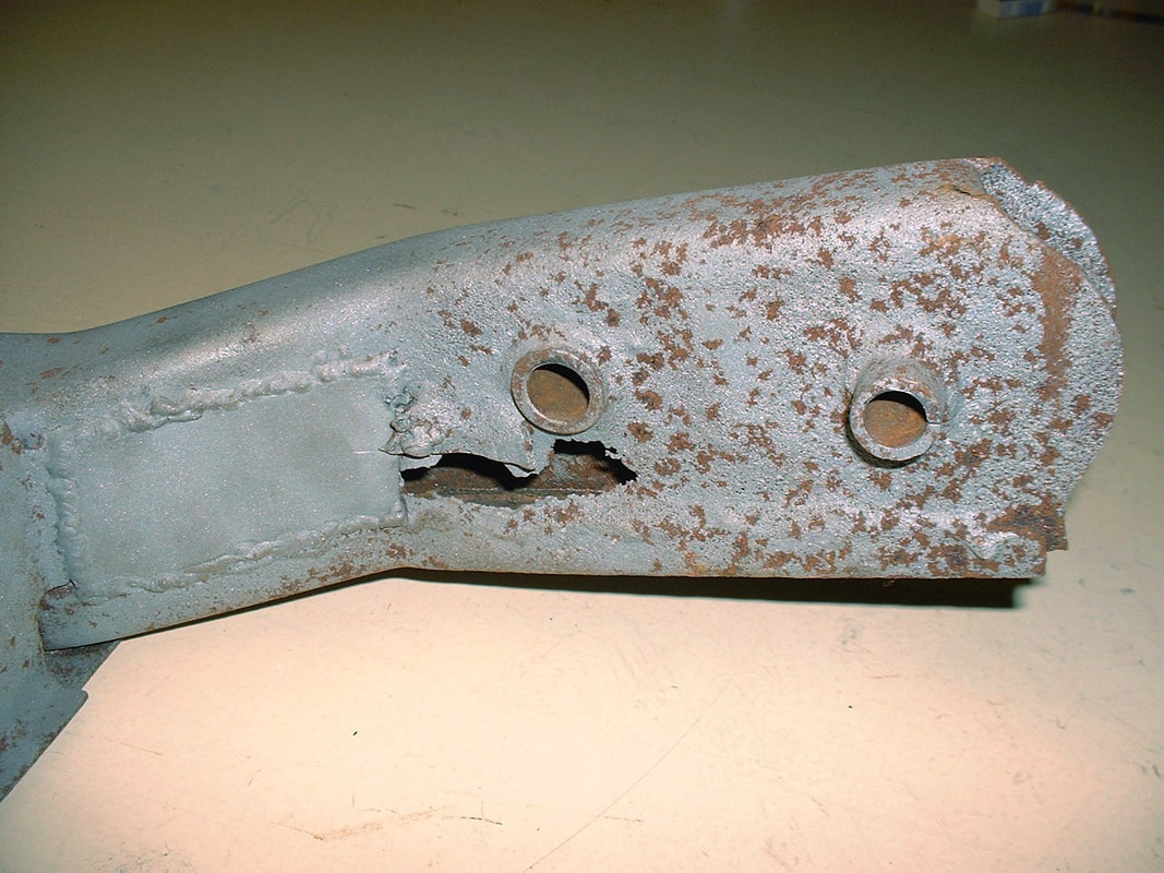
...and the main sub-frame mounts, though it appears someone tried to patch some of the damage at one point:
...and the main sub-frame mounts, though it appears someone tried to patch some of the damage at one point:
I drew out the stock sub-frame first, since it forms the basis for the attachment of the engine, transmission, and suspension to the chassis. Here’s the result:
I drew out the stock sub-frame first, since it forms the basis for the attachment of the engine, transmission, and suspension to the chassis. Here’s the result:
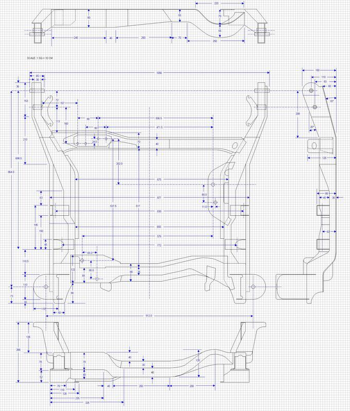
The next logical step was to draw the main chassis showing how the sub-frame sat in relation to it. While it was only critical at this stage to draw the location of the strut tower, drawing the entire rear chassis proved very beneficial later on to set the location of the new engine and transmission. Here are the three views:
Frame Side View:
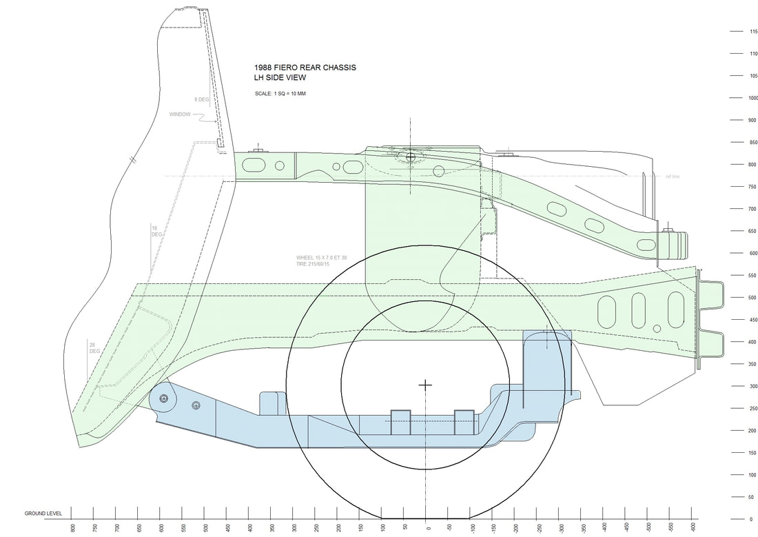
The side view shows the Fiero's longitudinal frame members best. An upper and a lower frame rail are attached to the firewall and extend rearward where they are joined vertically by the strut tower. From there, they extend rearward where the lower rail terminates with the bumper bar, and the upper rails are bridged by a transverse member.
Frame Top View:
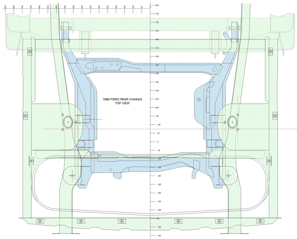
The top view shows the transverse members more effectively. It also shows how the lower frame rails converge toward the rear of the chassis.
Frame Rear View:
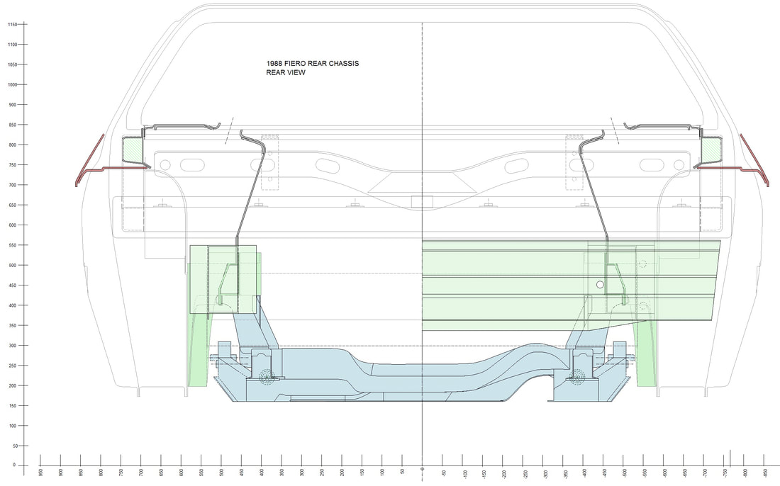
Finally, this rear view (with cutaway rear bumper bar) shows how the strut towers encroach into the available space for the engine. Also clear is the strut tower brace that's an integral sheet metal stamping in the forward trunk wall.
Finally, this rear view (with cutaway rear bumper bar) shows how the strut towers encroach into the available space for the engine. Also clear is the strut tower brace that's an integral sheet metal stamping in the forward trunk wall.

 RSS Feed
