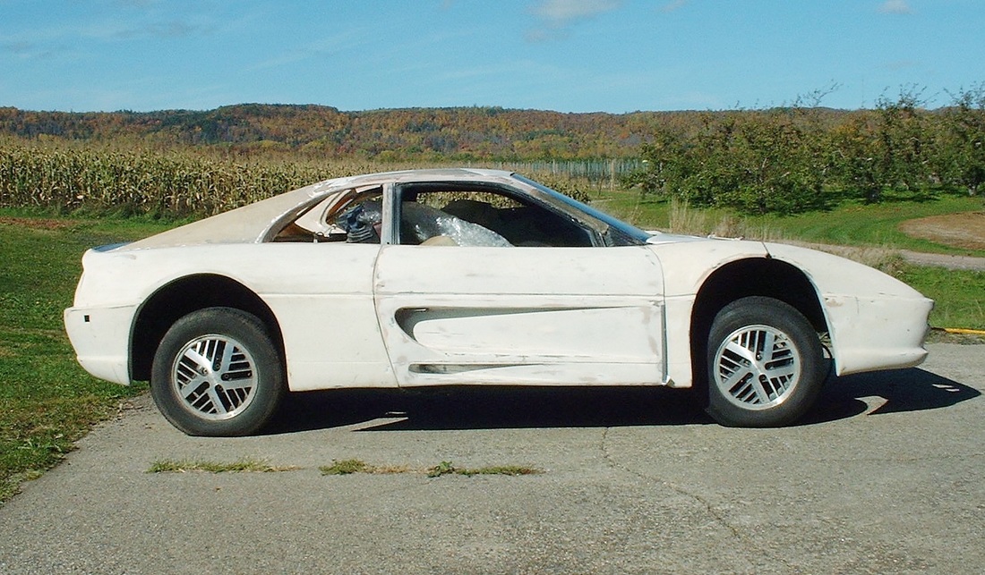
This post is about how I planned to make the rear wheels fit the fender opening. So here was the starting point... in fact I don't know what made me think this could ever be made to look right:
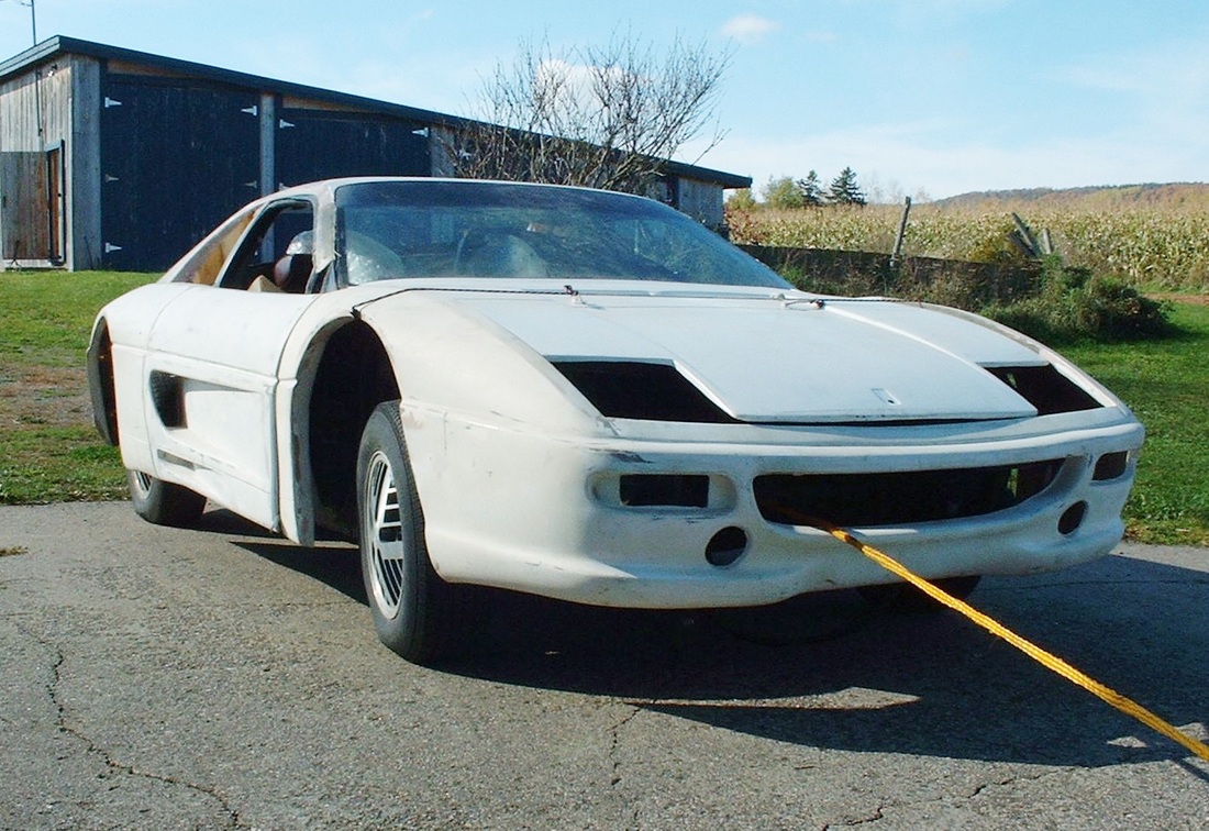
And from this view you get a better idea just how far inboard the stock rear wheels sat in the fenders:
I decided the first step was to measure just how far the new body work stuck out from the stock rear wheels. Once that was done I added a drawing of the F355 fender in cross section to one of my earlier chassis drawings and came up with this:
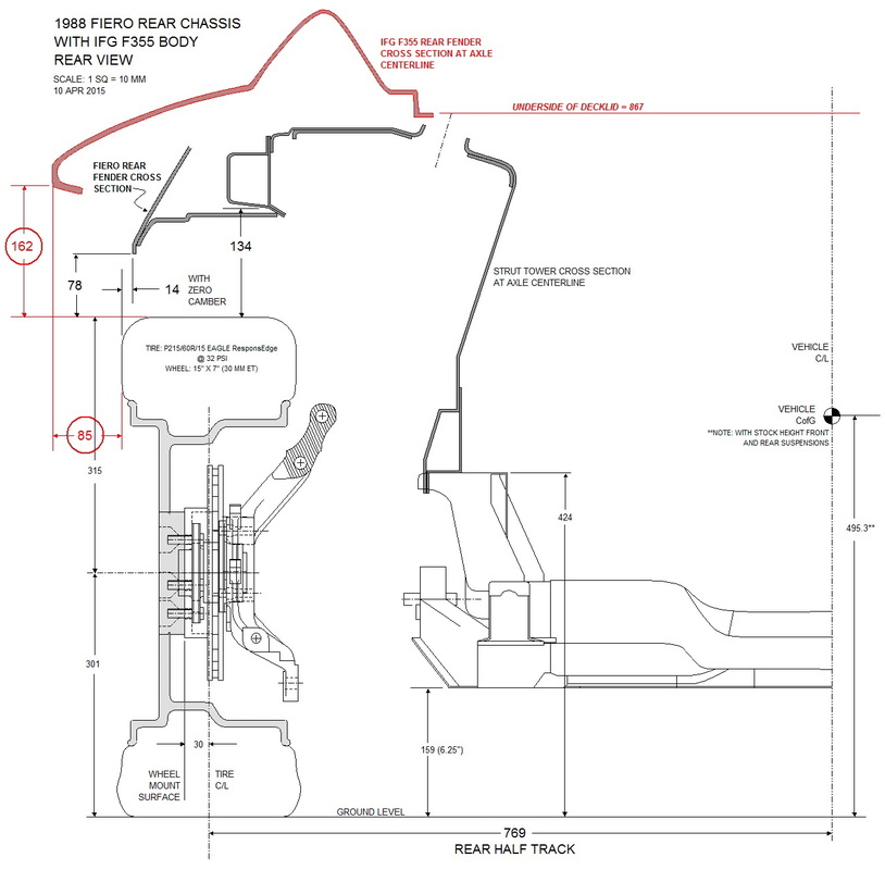
In the drawing above the black lines are the stock Fiero chassis parts and measurements, while the red lines and numbers show the magnitude of the problem I was dealing with. Although I was never planning to use the stock size wheels and tires, they provided a good benchmark from which I could compare the effect of new wheels and tires. The height of the wheel gap between the stock tires and the Fiero fender measures 78 mm which is a large gap by modern standards. The 162 mm gap that existed between the stock tires and the new F355 body work was just out of this world. That's a whopping 6-3/8"!
The other important dimension in the above drawing is the depth the stock wheels and tires sat in relation to the outboard lip of the fender. On the stock Fiero, the rear wheel actually sticks out by about 14 mm from the Fiero fender lip whereas with the much wider F355 fenders the stock wheels sat 85 mm inboard. It's no wonder the stock suspension and wheels look silly under those huge Ferrari fenders.
Since I was going to design the new suspension from the tires up, I looked long and hard at various aftermarket wheels before deciding on 18" x 9" wheels with a 45 mm offset mated to 265/35/18 tires, then added them to the drawing where I wanted them to be located (I've greyed-out the stock wheels and tires):
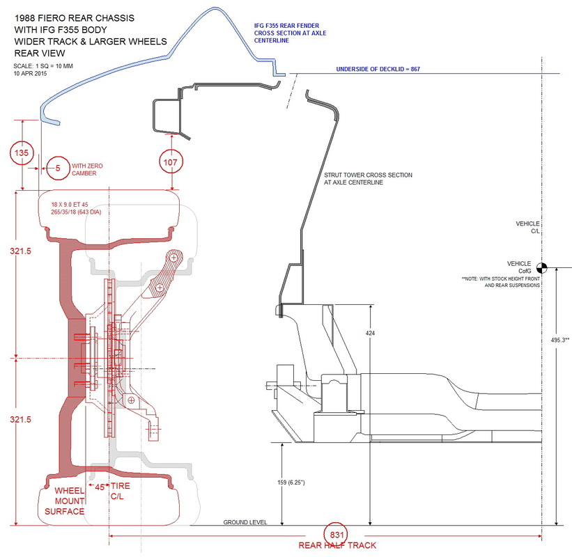
The taller aftermarket wheels would normally also raise the stock ground clearance but for the purpose of this exercise, I kept the chassis at the stock height. All of the numbers in red are the measurements that changed as a result of the larger diameter wheels and new location. The circled ones are the most important numbers. By simply adding new wheels and tires, the fender gap dropped by 27 mm, a little over an inch... I was aiming to find another 84 mm.
The next stage of fender gap reduction came from the innovative idea of cutting down the engine cradle mounts by 25 mm in height. By keeping the engine cradle at the same overall height from the ground, the impact of shaving the mounts would be that the chassis (less the cradle) would drop by 25 mm taking the fenders along with it. To illustrate this, notice how the height of the engine cradle's "legs" have been shortened to 399 mm vs the stock height of 424 mm:
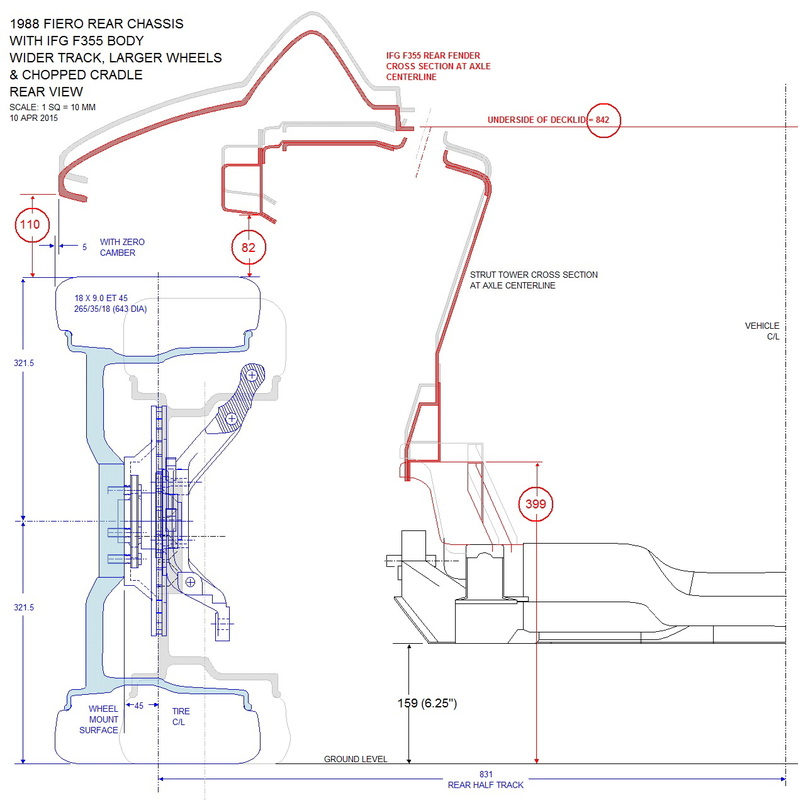
Once again, all of the measurements that changed between this drawing and the last drawing are circled in red. The most noteworthy measurement is the drop in the fender gap from 135 mm to 110 mm.
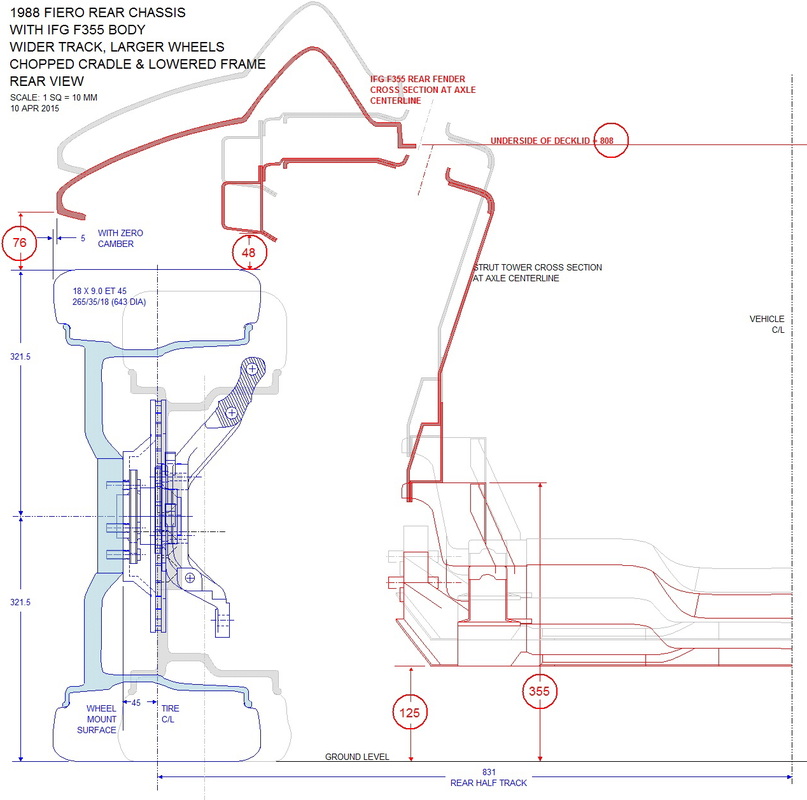
The next most logical place to lose more height was by reducing the ground clearance. I felt safe to reduce the clearance of the engine cradle to the ground by 34 mm to 125 mm with the following effect on the rest of the measurements:
At this point the fender gap was getting down to a respectable height, though still too high for a sports car. I had pretty much run out of options to reduce the fender gap any further when a friend I met on the internet (Don Ostergard) suggested modifying the fiberglass. That was the kind of outside-the-box thinking that gave me the last piece of the puzzle. I lowered the digital profile of the fender lip 25 mm and finally had the 51 mm gap I was shooting for, while maintaining a decent ground clearance of 125 mm:
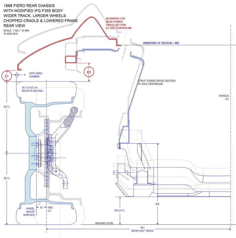
Even at this early stage I knew I wanted my suspension to be able to travel 76 mm upwards (in jounce) without interfering with anything. That's when I realized the upper frame rail would need to be notched as shown above. I gave myself 7 extra mm of clearance (to 83 mm) for good measure.
With this exercise completed, the basic relationship between the chassis and the knuckle was defined. But before I could start interconnecting the two with a new suspension design, I needed one more piece of information: the space the engine and transmission would occupy. That's the subject of my next post.

 RSS Feed
