With the engine and transmission drawings complete, I digitally mated them together and started playing around with the optimal location of the powertrain within the engine bay. In my last post I mentioned the need to situate the powertrain vertically, laterally, and longitudinally. There wasn't much room in any of the three axes to play with.
Vertically, there was a scant 30 mm difference between the height of the engine bay and the engine itself. I decided to set the lower edge of the oil pan 10 mm above the bottom edge of the cradle, leaving 20 mm between the top of the engine and the underside of the decklid. That decision automatically created a misalignment height-wise between the differential output and the centre of the wheel. That would result in the axles being angled downwards towards the centre of the car by 48 mm over a span of about 400 mm. The resultant axle angle would be about 6.8 degrees (as viewed from the rear) on the driver's side axle (the worst case)... well within the maximum 23 degree operating range of a typical CV joint.
Next, to situate the engine fore and aft (longitudinally) in the engine bay, it would've been best to locate the differential outputs with the centre of the wheels as viewed from the top. Unfortunately the lower frame rails narrowed too quickly and prevented me from shoving the powertrain that far back. I settled on a location which placed the differential ahead of the wheel centres by 20 mm. That gave the axles a 2.9 degree cant backwards as well. The engine still interfered with the forward trunk wall but that wasn't a serious problem.
Finally, for the transverse positioning of the powertrain, I had approximately 35 mm to play with between the overall length of the powertrain and the width between the lower frame rails. No matter where I placed the engine side to side, the passenger strut tower interfered with the aft valve cover so I chose to move the powertrain to within 10 mm of the driver's side rail and recognized I'd have to make changes to the strut tower on the passenger side. The resulting three-view drawings are what follow along with a detailed look at the remaining problem areas (highlighted in red) that would need to be sorted out. Here's the side view:
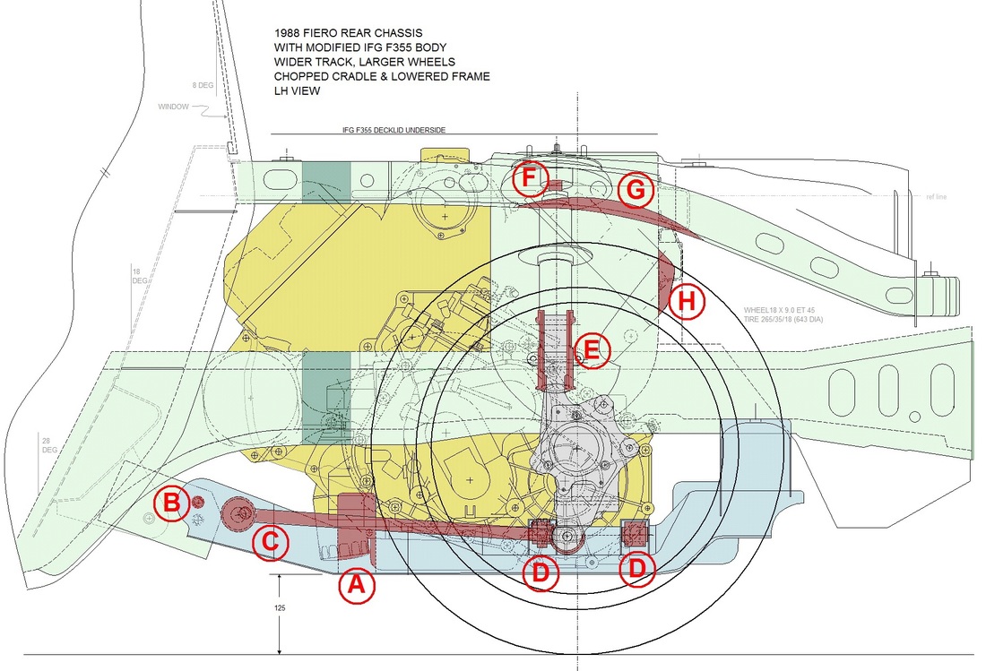
Once again, even though I knew I would need to design my own engine sub-frame and likely much of the rear suspension, I used the stock parts as a baseline from which to make observations. I listed the problem areas alphabetically on the drawing to make it easier to follow along:
A. Stock cradle to engine interference:
The engine block and oil filter want to occupy the same area as the front cross member on the cradle. My new cradle design will simply move the front cross member further forward;
B. Stock forward cradle mount to chassis misalignment:
Having shortened the rear cradle mounts by 25 mm (in post #29 to lessen the wheel gap), one side effect was that the forward cradle mount also got raised in relation to the chassis, no longer aligning with the forward chassis hole. Again, the easy fix here is simply to design my new cradle to take into account the misalignment;
C. Trailing link angle change:
Lowering the chassis on the wheels and adding taller wheels had the combined effect of compressing the suspension. That, in turn, changed the angle of the trailing link from 12 degrees to just 3.9 degrees from horizontal. This would have a devastating effect on anti-squat as shown in post #24. The fix for this would come from raising the front mounting point of the trailing link to re-establish the correct angle;
From here I'll skip over areas D, E, and F since they're best seen in other views.
G. Tire to upper frame rail interference:
I covered this problematic area in post #29 where, after lowering the chassis, I discovered that to maintain 76 mm of suspension travel upwards, I'd need to notch the upper frame rail. This view shows a better profile of the frame notch; and
H. Aft valve cover to forward trunk wall interference:
As mentioned earlier in this post, when I located the powertrain fore and aft, I had to trade off some axle alignment with some interference between the aft valve cover and the trunk wall. The easy fix for this is simply making a clearance bulge in the trunk wall.
Here's the view of the same problematic areas from the rear view:
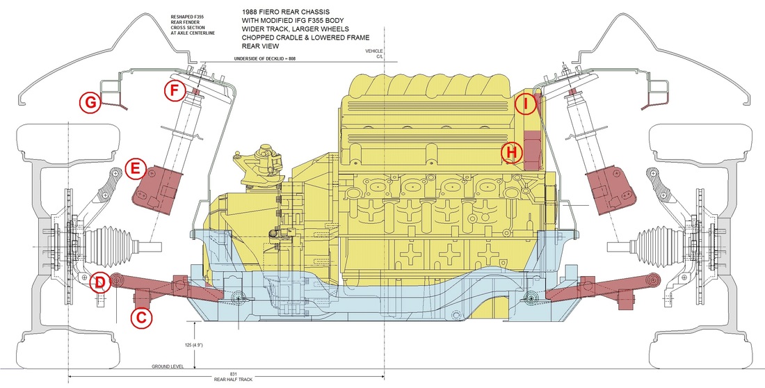
The rear view shows other issues for point C, and better views for points D, E, F, and I:
C. Trailing link offset incorrect:
Aside from the trailing links being at the wrong angle as mentioned above, the other issue is that by having moved the wheels outboard, the stock trailing links would no longer have the correct dimensions to span the distance from the cradle mounts to the bottom of the knuckle. The solution for this would be to fabricate new trailing links with the correct offset;
D. Lateral link angle change and length:
Apart from the obvious problem of the lateral links being too short for the new track width, lowering the ground clearance of the chassis and adding taller wheels changed the angle of the lateral links from horizontal to about 8.5 degrees upwards. As shown earlier in posts #25 thru #28, this would have a negative impact on everything from camber to toe to roll centre changes. The fix for this would be to raise the inboard mounting points of the lateral links to re-level them, and to lengthen the links. That would present another problem though... the higher mounting points would interfere with the transmission. Alternately, the inboard mounting points could be moved outwards to clear the transmission, then upwards, reducing the need for longer lateral links;
E. Lower strut to upper knuckle gap:
Moving the wheels outboard cause the knuckles to move away from the lower strut mounts. The struts can't simply be re-angled to broach the gap for several reasons. The most important is that there would be a significant impact on camber and roll centre changes as shown earlier in posts #25, 26, and 28 because of the importance of the strut angle on these parameters. Of lesser importance, the mounting holes wouldn't align. One solution would be to fabricate an adapter to take up the space between the lower strut and the knuckle. An alternative would be to design an upper control arm for the top of the knuckle. This would also have to be accompanied by replacing the strut with a shock absorber that pivots at both ends. Doing so would change the way camber and roll centre changes are calculated and provide much greater control over these parameters;
F. Strut travel limited:
As seen above, one impact of having lowered the chassis on the suspension is that only 25 mm or so remain in the strut's upward travel. My design criteria to have 76 mm of travel in both jounce and rebound would not be possible with the stock strut. One solution would be to source struts with shorter bodies that have compatible mounts, but an alternative would be to use a pushrod and bell crank system at the top of the knuckle and relocate and reorient a pair of shock absorbers to where there is more space; and
I. Passenger strut tower to aft valve cover interference:
As mentioned earlier, to minimize the rearward cant of the axles (as viewed from above) the optimal fore/aft location of the powertrain meant that the aft valve cover would protrude not only into the trunk area (H), but also interfere with the passenger side strut tower. A solution would be to make a clearance bubble in the strut tower. Alternatively, if a pushrod shock absorber system were employed, the strut towers could be eliminated altogether.
Although all of the problem areas can be seen from the above two diagrams, the top view of the chassis and powertrain provides additional perspectives of many of them as well:
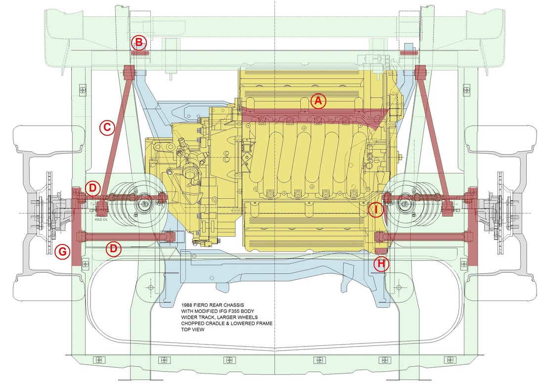
With the optimal location of the powertrain decided, as well as having identified any remaining problem areas with that choice, the space limitations for a new suspension system were much clearer. Next up: deciding on the new suspension and cradle configuration.

 RSS Feed
