After the previous post, I was finally ready to commit to a suspension strategy. For the lower end, I would design a new engine sub-frame and for the upper end a pushrod shock absorber system with upper lateral links to control the knuckle. I started with the cradle since most of the characteristics were already known. It needed:
- wider side rails to allow the powertrain to sit entirely within its borders;
- taller side rails to accommodate raised lateral link mounts;
- a front cross member moved forward to clear the oil filter and aligned with the forward engine mount;
- shortened rear mounting legs to lower the entire chassis;
- lower front mounting eyes to accommodate the lowered chassis;
- relocated trailing link mounts from the cradle to the chassis; and
- lateral link mounts moved forward to accommodate a new issue: swapping the knuckles left to right and vice versa.
Here's the top view of the new design overlaid onto the stock cradle for comparison:
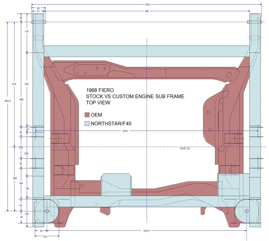
GM deliberately kinked the side rails inward to get as much length on the stock lateral links as possible, whereas my wider and straighter (and stronger) side rails were designed to shorten the links on the much wider track.
The side view shows how I stepped the side rails to raise the mounts for the lateral links as well:
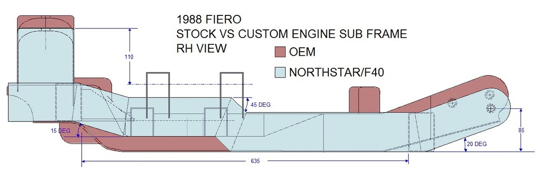
The other obvious change from the side view is how I advanced the mounts for the lateral links forward. This has to do with having decided to swap the knuckles side to side. I'll explain why I did this later in another post.
Lastly, here's the rear view of the two cradles:
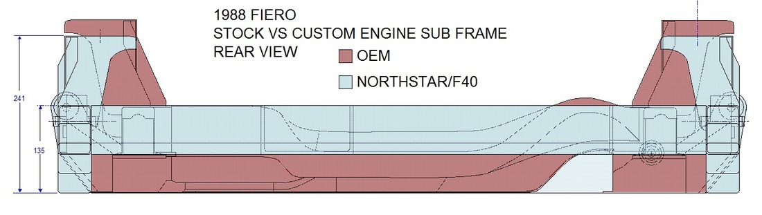
The drawing above shows how I decided to use the rear mounting legs from the original sub frame after they had been cut down 25 mm. I also swapped sides for these parts to ensure the loads would be distributed to the corners of the new wider cradle where it is stronger.
I double checked my measurements and the interfaces between the new cradle, powertrain, and the chassis digitally before making a template for the side rails:
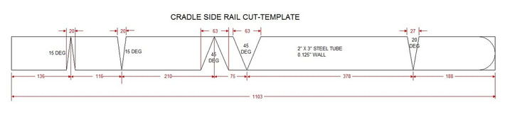
Then I finally got back to fabrication! I used 2" x 3" x 0.125 wall thickness steel tubing and notched it with pie shaped wedges using an angle grinder and a thin cut-off wheel:
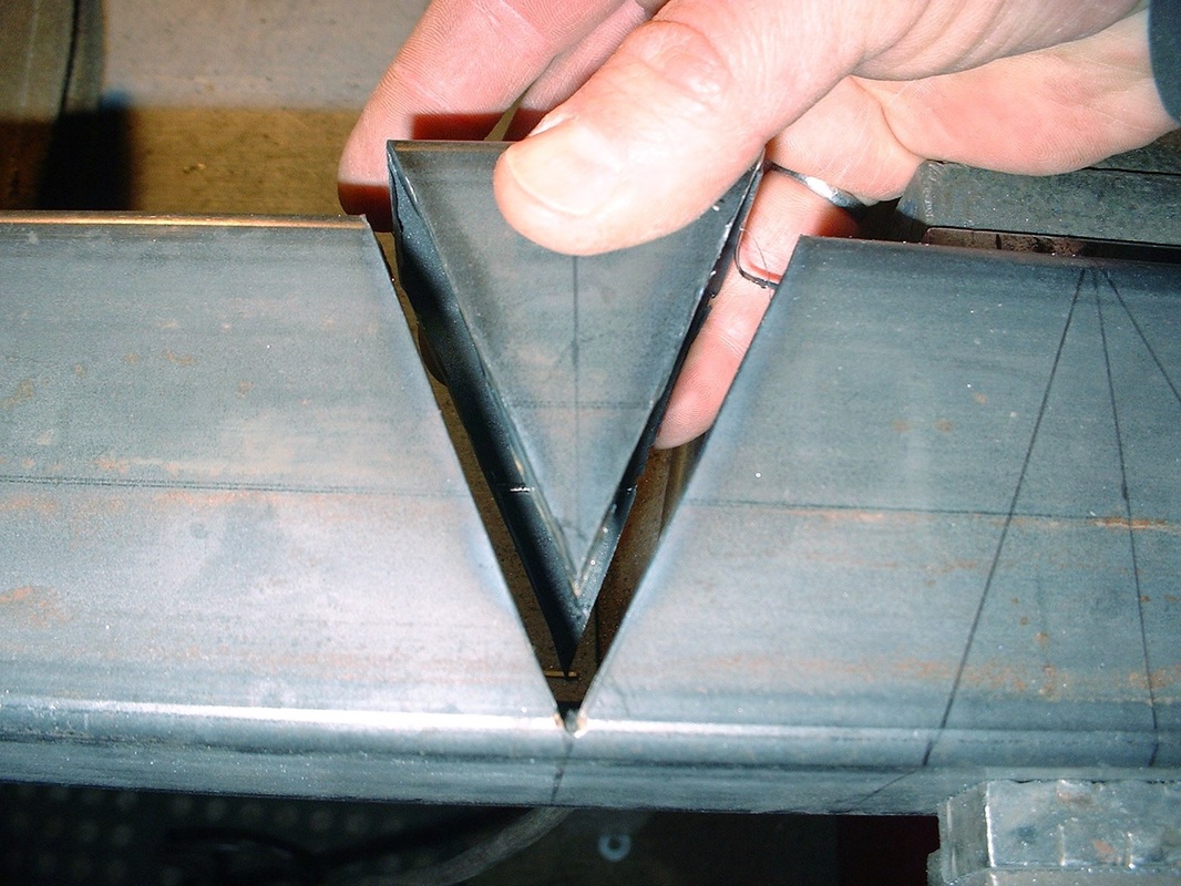
Five notches were required per side rail as shown on the template. Once they were notched, the side rails were ready for bending and welding:
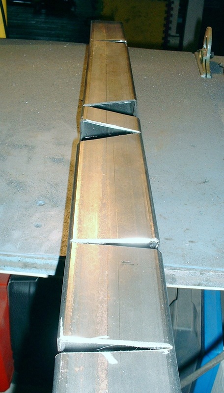
Here they are after welding:
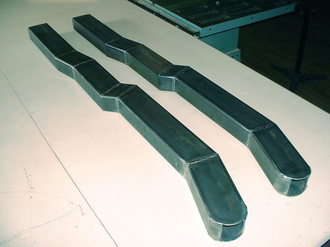
The front and rear cross members were straight lengths of the 2" x 3" rectangular tubing, so once cut, they were easily welded to the side rails:
Next came cutting the rear mounting legs off the stock cradle...
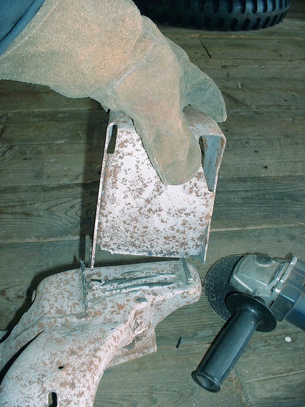
... cutting them down 25 mm...
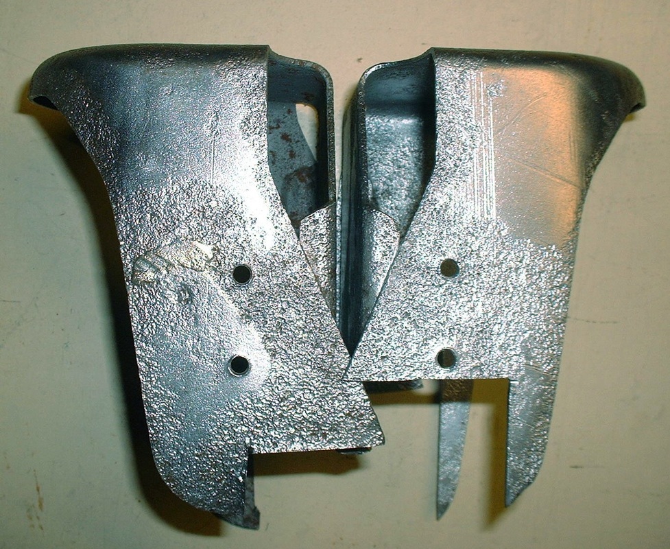
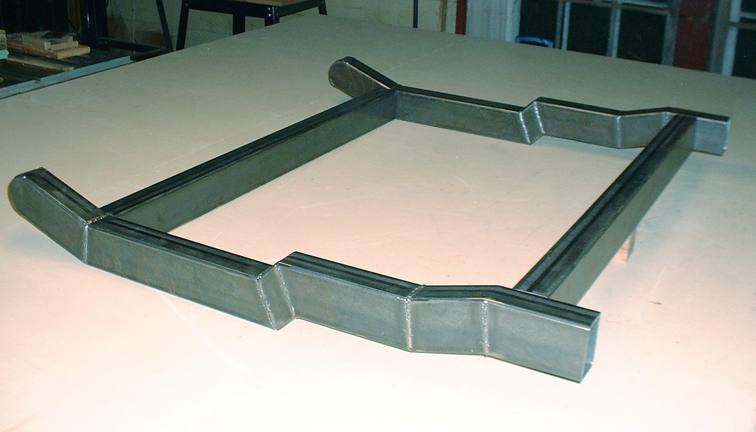
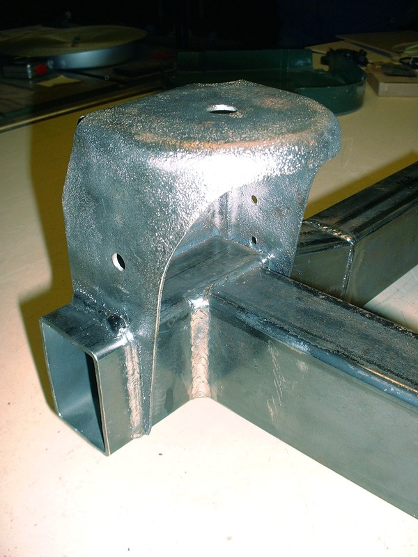
...and welding them onto the rear corners of the new cradle:
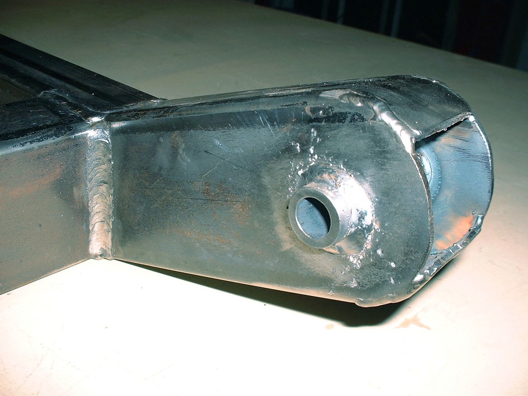
The last thing for the basic cradle was to weld structural tubing in the side rails for the forward cradle mounts:
Next up: designing the engine and transmission mounts.

 RSS Feed
