Rather than simply head blindly into the design of the engine and transmission mounts, I decided to do a bit of research into modern techniques and materials. It seems it's an entire field of it's own with designers calculating the engine's CofG, bending and torsional characteristics of the block(!), anticipated stresses in fore and aft, vertical, and torsional planes, vibration characteristics of the engine at various RPM's, the characteristics of the rubber in the mounts, and on and on! Then, a whole slew of other factors are considered with transverse engines since all the differential loads are transmitted to the mounts as well. Whew! My head was spinning.
To make things as simple yet effective as possible, I decided that the Cadillac engineers must've done their homework in this area and that I wouldn't reinvent the wheel if I could adapt the OEM Northstar mounts to my new cradle. I already had two torque struts and a usable lower mount and mounting bracket.
I measured up the necessary Cadillac mounting location dimensions from a buddy's DeVille and plotted where they would end up on my custom cradle. After some massaging due to differences in the transmissions, I came up with this layout (as viewed from the RH side):
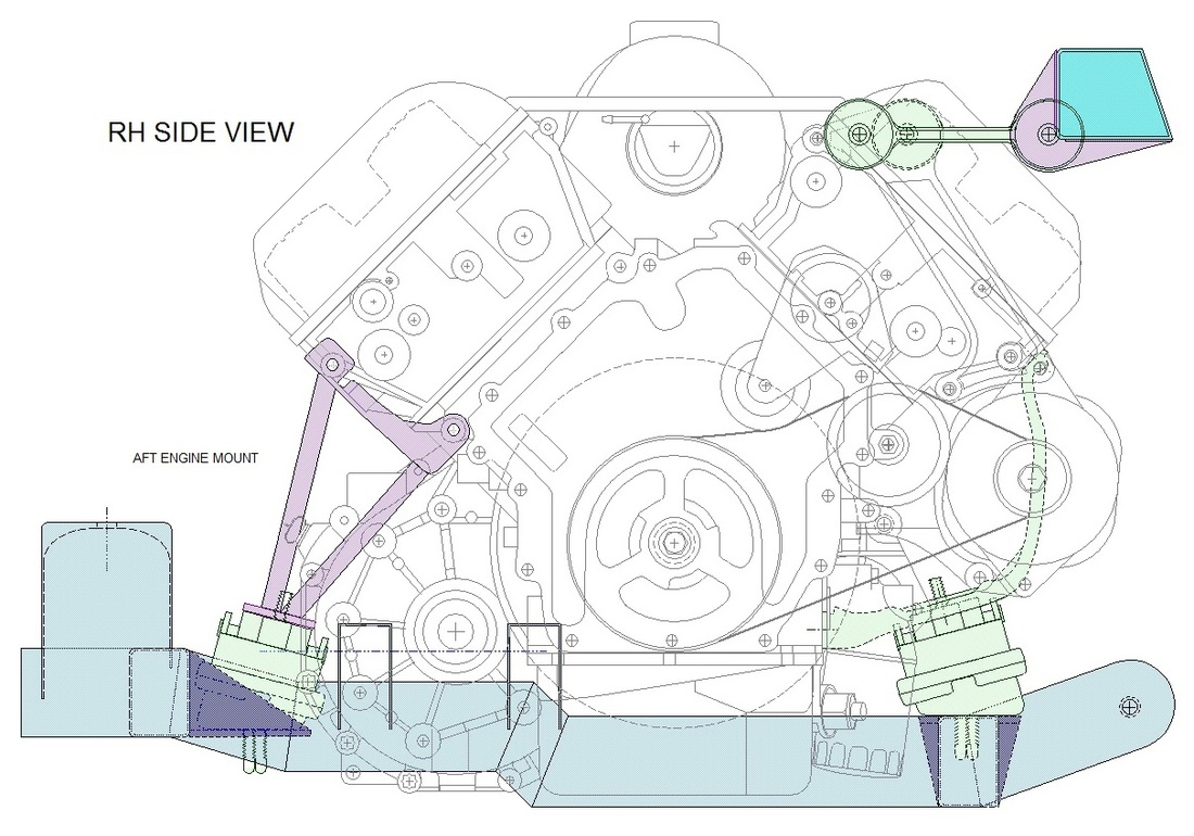
The upper end makes use of the stock engine torque struts by anchoring them to a new transverse structural beam (teal colour) under the rear window spanning the two upper frame rails. It has an odd cross section to account for the 15 degree slant in the rear cabin firewall.
The lower end consists of a stock Caddy engine bracket and hydraulic mount to the forward cradle cross member, a custom bracket connecting a second hydraulic mount to the aft side of the engine, and another custom bracket connecting the transmission to the cradle with a third hydraulic mount. The transmission bracket is shown in this next view, where the engine mount has been left out for clarity:
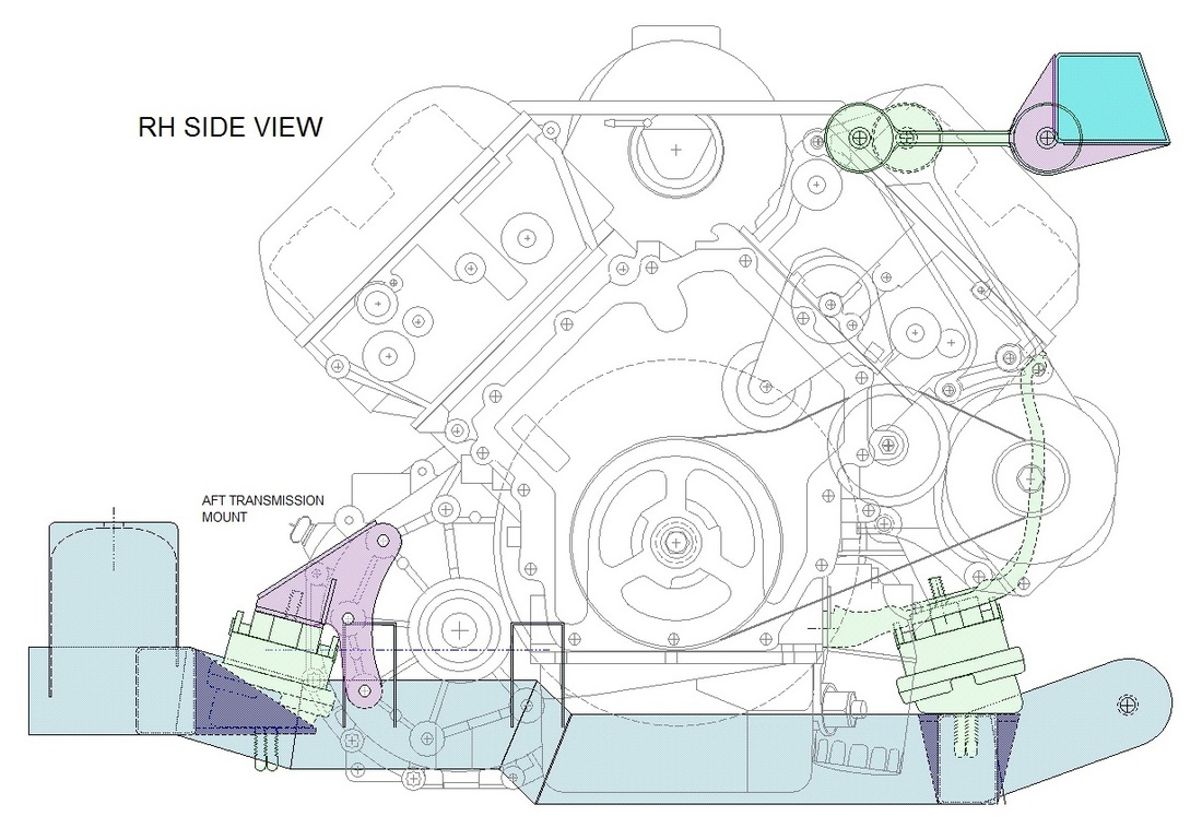
I was able to keep the two torque struts and the forward engine mount at exactly the same location as the Caddy, however the two aft mounts are relocated to better suit the manual transmission. The aft view shown next gives another perspective of all except the front engine mount:
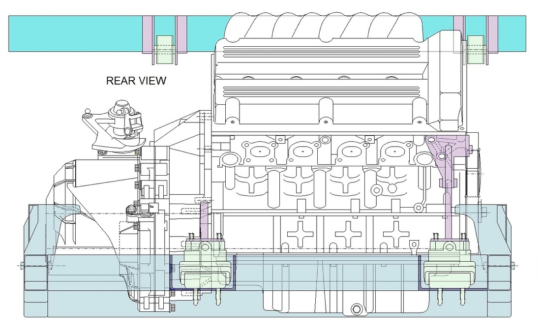
You'll notice in the above drawing that the torque strut on the left hand side appears to be floating in thin air... that's because it attaches to a bracket on the coolant manifold, which I was too lazy to draw!
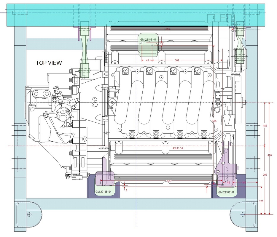
Finally, the top view show all three powertrain mounts as well as the two torque struts. I've made various parts semi-transparent in order to see the mounts better in all three views.
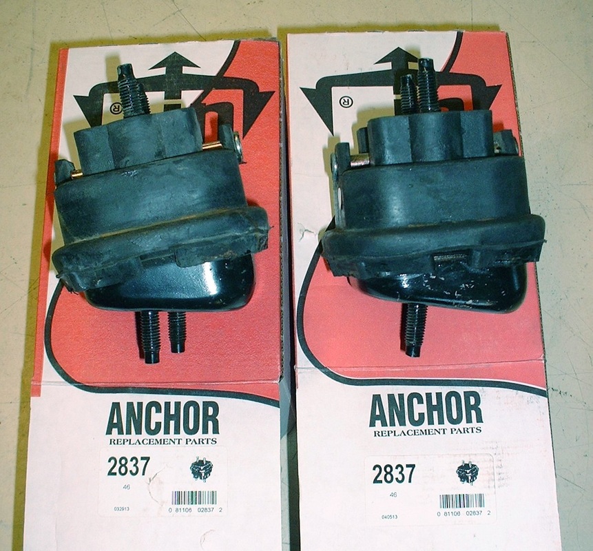
To get started on the fabrication, I located two more Caddy hydraulic mounts at NAPA for a mere $16 each! Even after factoring in the shipping costs of $32 and taxes, I got both mounts for a total of $75 within a week of ordering:
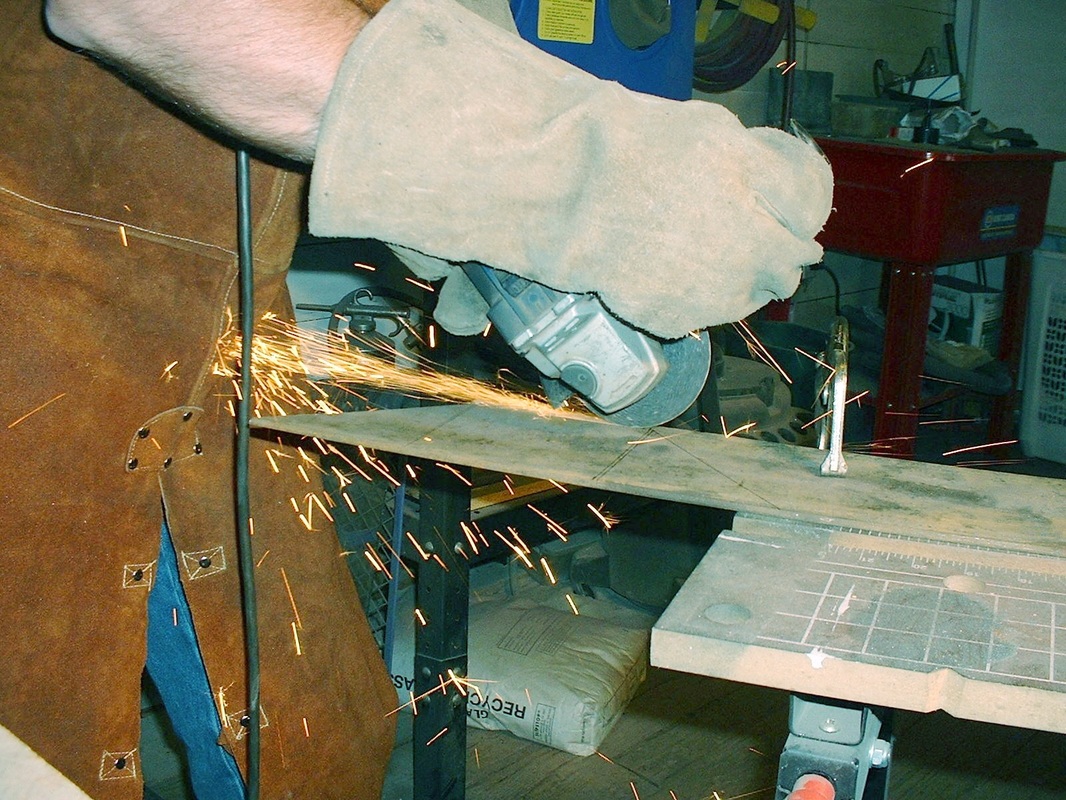
With the rubber mounts on hand, I started work on the brackets that were needed to hold them to the cradle (the dark purple parts in the above drawings). I bought some 4" wide X 3/16" thick steel bar and got busy cutting out the patterns I'd made on the computer. I used my angle grinder with a cut off wheel:
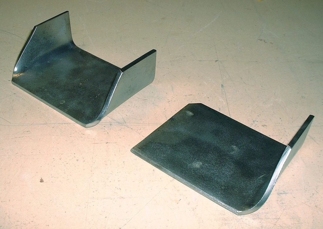
Using a 12 ton hydraulic press and a set of 90 degree dies, I bent integral gussets into the plates to give them greater bending rigidity and more surface area for welding. Here they are after sandblasting:
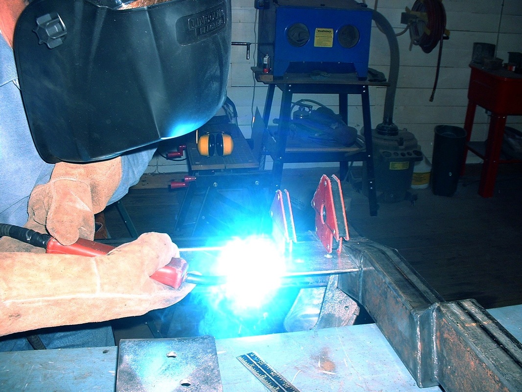
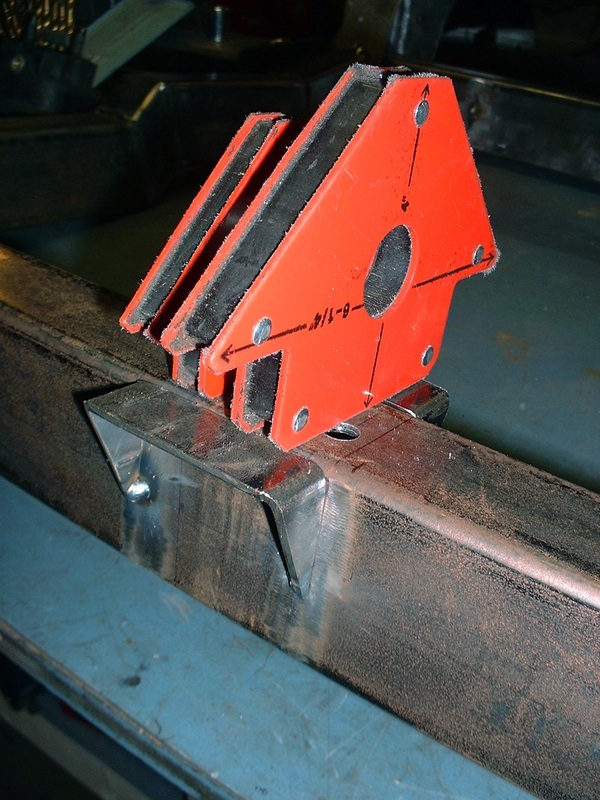
Once I was satisfied with their dimensions, I drilled the mounting holes for the hydraulic mounts and tack welded the plates on the rear cross member:
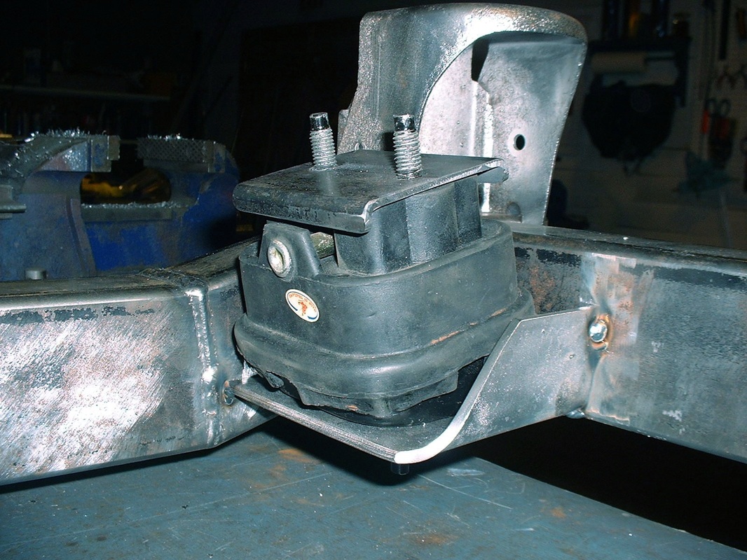
Then I mocked up the aft hydraulic mounts onto the newly tacked platforms. Here's the aft engine mount:
The front engine mounting platform was considerably easier since the hydraulic mount would rest directly on the top side of the front cross member. I needed to add a couple little "wings" to match the size of the hydraulic mount's base though:
Here's the forward engine mount, complete with the stock Caddy engine bracket mocked up:
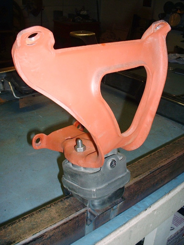
In my next post, I'll cover the fabrication of the brackets (like the reddish one above) that bridge the aft hydraulic mounts to the engine and transmission.

 RSS Feed
