I mentioned in an earlier post that I decided to flip the rear knuckles left to right and vice versa. I discovered during one of my many design iterations that the stock knuckle orientation left very little room for an upper link in the hashed area in the diagram below:
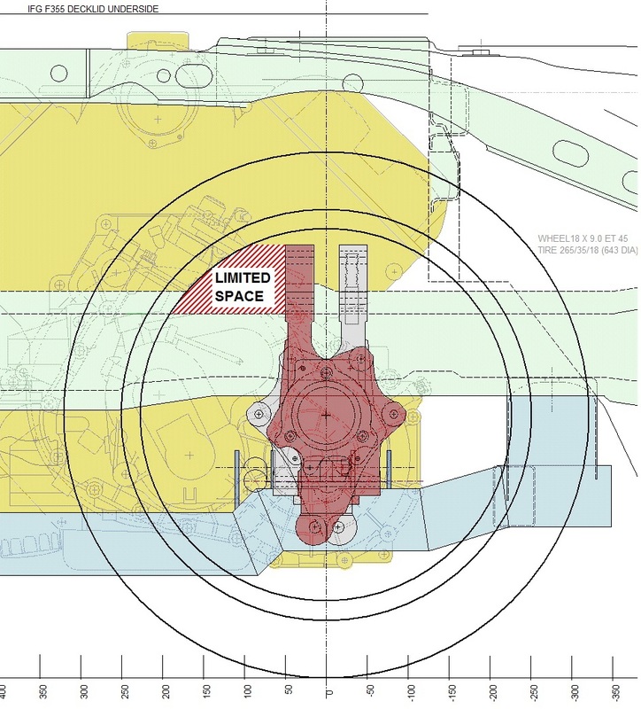
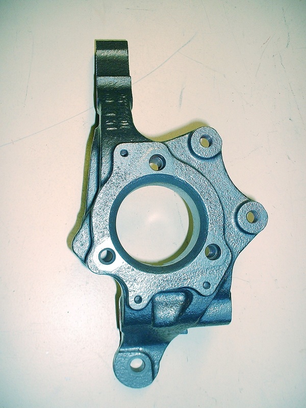
A suggestion from an on-line friend made me realize that flipping the knuckles side to side would increase the available area since the top part of the knuckle is offset from its centreline. The grey knuckle in the background illustrates how much of an effect this had. Here's a look at the actual part:
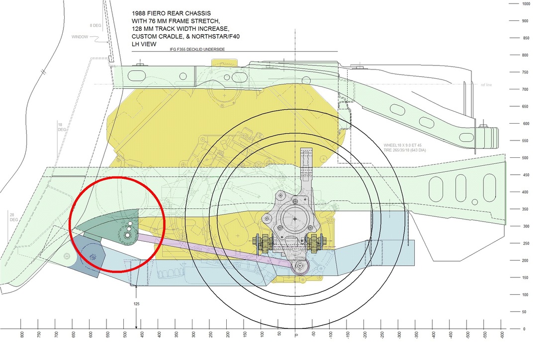
With the orientation of the knuckle finalized, I could move on to designing the trailing link mounts. As discussed in post #24, the angle of the trailing link (as viewed from the side) is what determines the amount of anti-squat generated by the suspension. I wanted to keep the stock amount of anti-squat and since I already knew the location of the trailing link at the knuckle, I only needed to locate the end attached to the frame and determine the length.
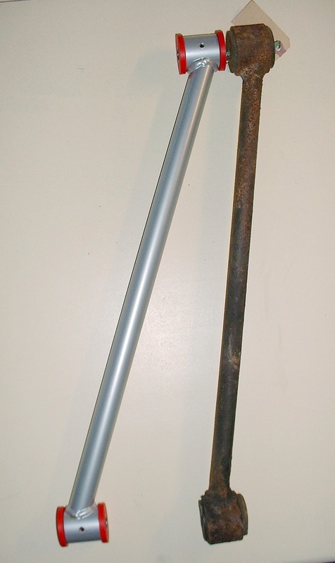
I already had a set of new trailing links made with the correct offset for the wider track from an earlier, abandoned design. Luckily they were salvageable for this design:
That automatically set the overall length of the trailing links so it wasn't hard to figure out where to locate the frame mounts if I wanted to keep the same angle as stock:
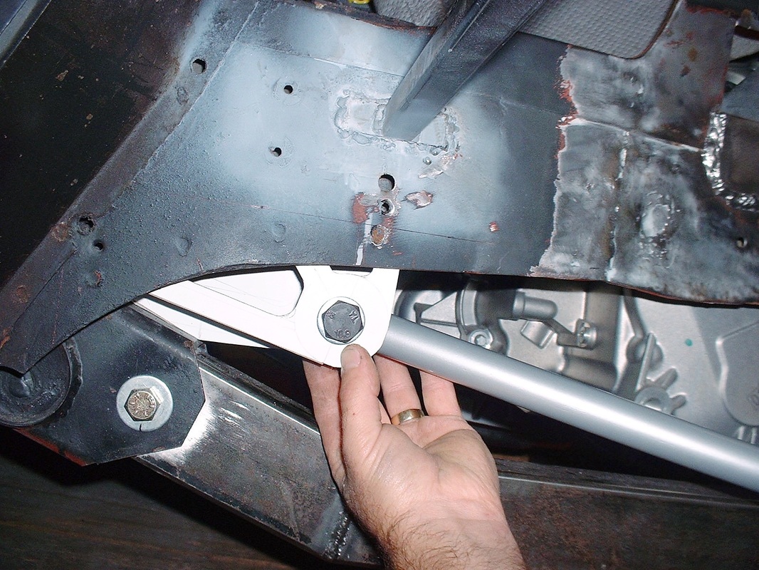
Unlike the stock configuration where the forward trailing links mount to the cradle, I decided to drop mounting ears down from the lower frame rail. The biggest challenge was that the underside of the lower rail is curved, and the rails converge toward the center of the car as well. Using a laser level I was finally able to come up with measurements for a two-part template to hold the trailing link in place. Here's what the template for the driver's side looks like (disregard the lightening holes):
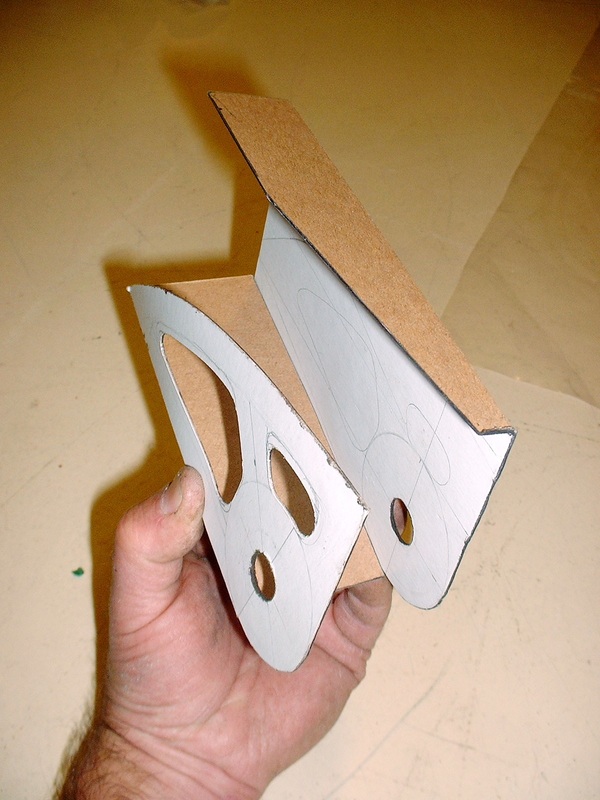
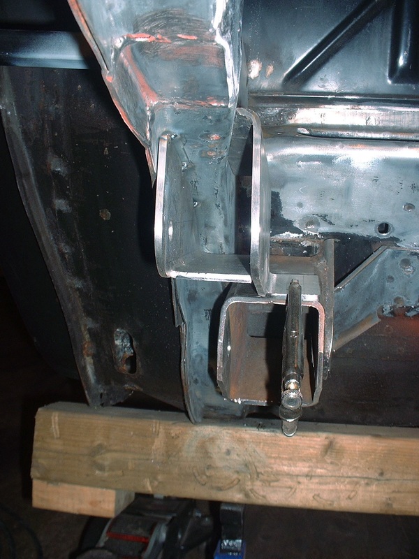
It fit the lower frame rail just behind the cabin, like this:
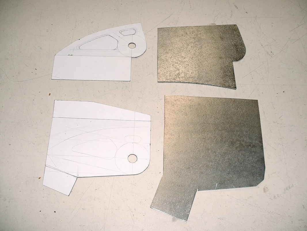
Once I knew the right dimensions, I cut them from 3/16" steel plate leaving extra material to give me leverage to bend them:
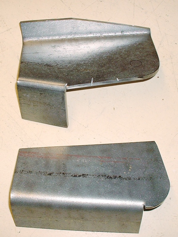
Here are inboard and outboard halves of one trailing link mount, fresh out of the press:
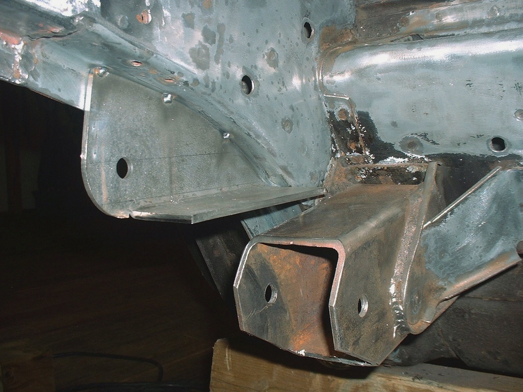
Getting the mounts in exactly the right position was much easier said than done. After several hours of fussing over the location, I finally tack-welded the outer half in place:
After the outer half was fully welded, the inboard half of the mount was installed. It was bent along the top to meet up with the side wall of the frame rail, and at the bottom it rests on the extended cradle mount. Once the mounting holes for the trailing link were accurately aligned, the inner half of the mount was welded securely to the outer half of the mount and to the frame.
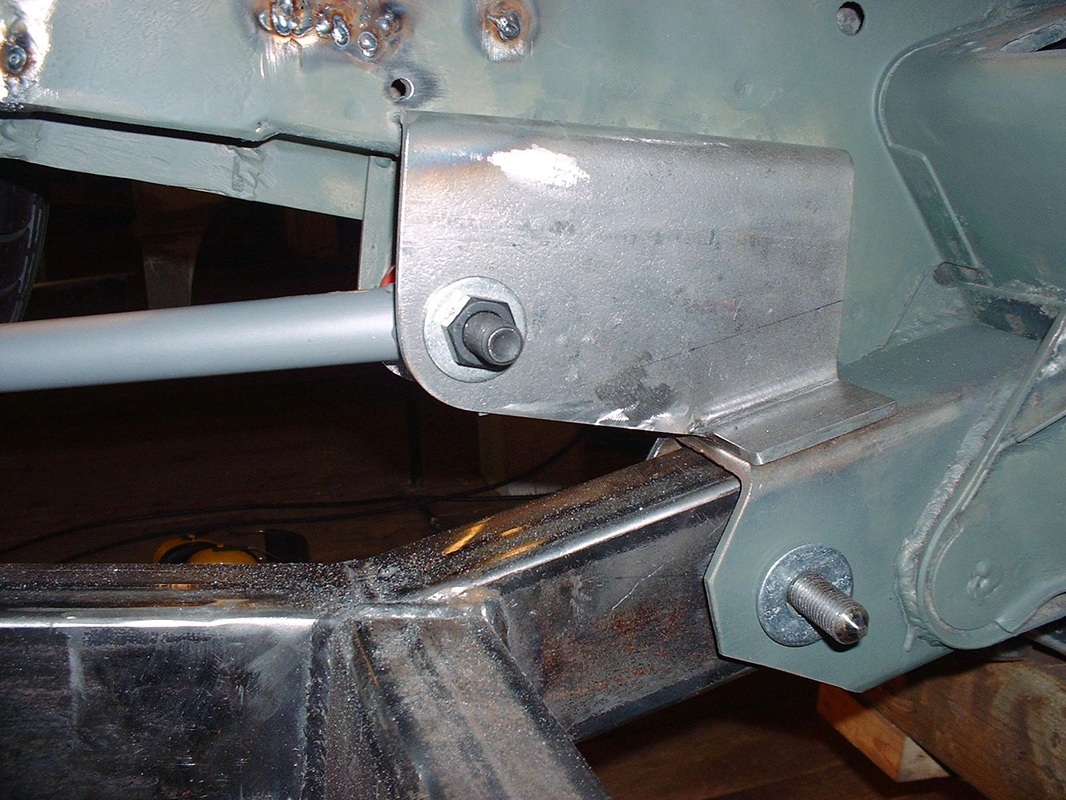
From this view it's easy to see how the new mount is full boxed.
That's one of five links done... 4 more to go starting with some research and buying the parts to fabricate the lower lateral links. That's next.

 RSS Feed
