Some of the specs for the two lower lateral links basically fell into my lap from my earlier drawings. Their length being determined by the distance between the mounting holes on the lower end of the knuckle and the new inboard cradle mounts. This top view shows them best, as well as the trailing link from the previous post:
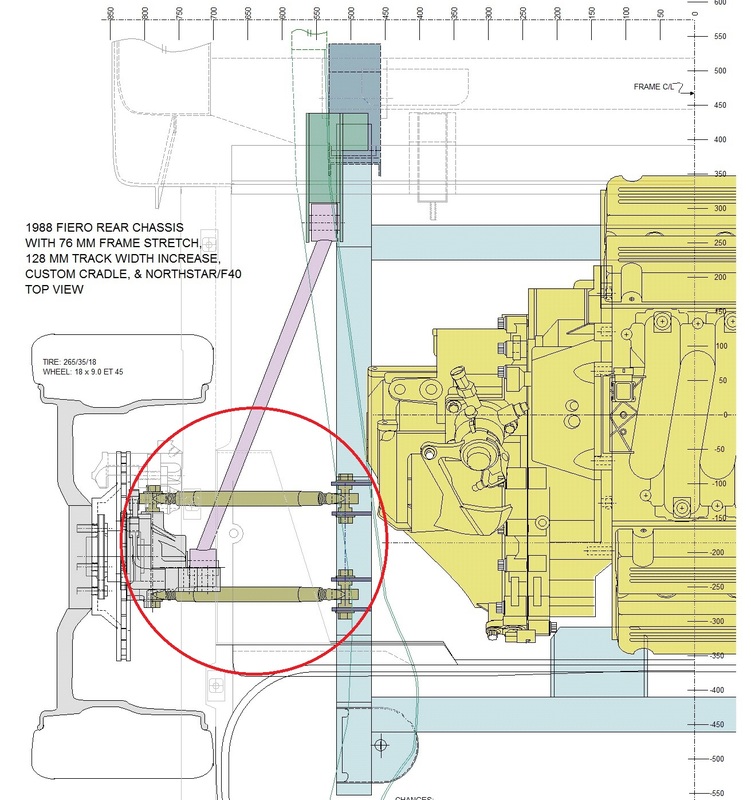
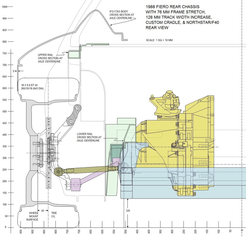
The eye-to-eye length for both the forward and aft links is 282 mm. Here's the view from the rear (they are the olive coloured links):
At this point, I needed to consider a basic loads analysis to determine the minimum material specs I would need for the links. I had decided early on that if I could find suitable hemispherical rod ends, that I would prefer these over rubber or polyurethane bushed links. These latter two options provide less accurate wheel control given their compliance under load. Hemispherical rod ends on the other hand are extremely accurate and shouldn't introduce any noticeable noise or harshness into the ride characteristics given the lateral link's role.
I only needed a rough idea of the magnitude of the loads so I created a diagram with the known dimensions as well as some approximate locations for the future upper links. All of these links are only subjected to lateral loads, and only during cornering. Since the loads are greatest at the outside wheels during cornering due to weight transfer, I looked at the lateral forces exerted by the road onto the outside tire at the expected limit of adhesion: 1G. That force at the tire contact patch (red arrow) is transformed into a moment (pink arrow) about the bearing, which is then resisted by the upper and lower link mounts (blue arrows) through the links.
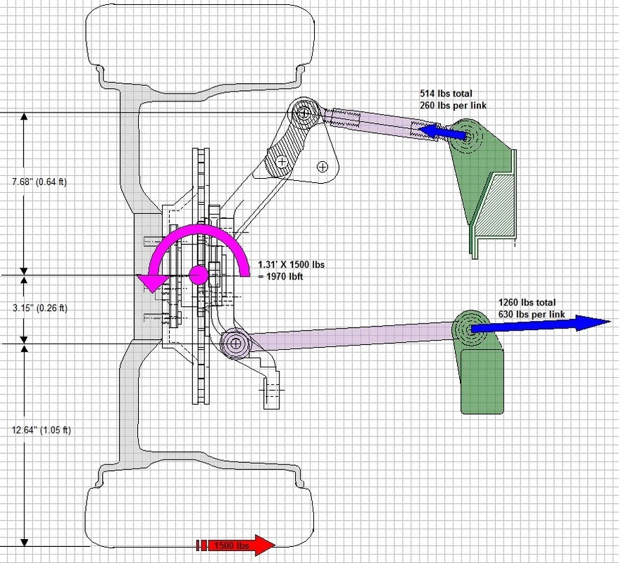
Bearing in mind the total lateral load is divided between the front and rear outside tires, the force on the rear tire won't exceed half of 1G (or approximately 1500 lbs). That results in a moment about the bearing of 1970 lbft that is reacted by the upper and lower link mounts. Solving for the forces at each mount, the lower link mounts will need to withstand around 630 lbs each and the uppers will need to react about 260 lbs each at max lateral G's. Normal driving probably won't generate half of the magnitude of these forces.
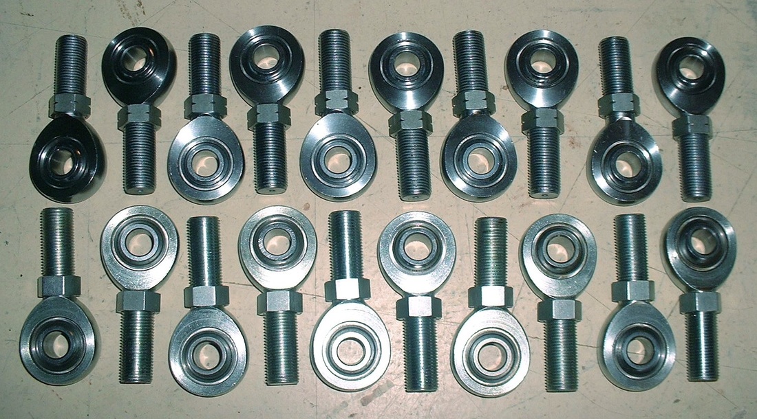
Knowing the 630 lb maximum load involved allowed me to research commercially available rod ends and swaged tubes. I looked at Summit Racing and Jeggs online catalogues and found some good quality Teflon lined rods ends from QA1. Their 3 piece, chrome-moly construction is certainly overkill for my application. Here are the remaining specs:
Rod ends (LH thread): QA1 3 piece PTFE lined 5/8"-18 male with 1/2" head bore, 31,390 lb load capacity, 10 deg misalign P/N: HML8-10T qty 10
Rod ends (RH thread): QA1 3 piece PTFE lined 5/8"-18 male with 1/2" head bore, 31,390 lb load capacity, 10 deg misalign P/N: HMR8-10T qty 10
I ordered enough to equip all eight lateral links and two shock absorber push rods:
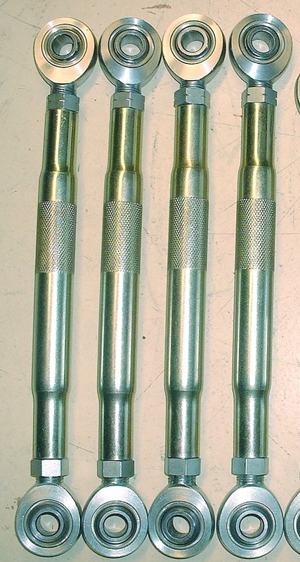
I also found some suitable 5/8" diameter swaged tubes from AFCO. They're formed using .095" wall DOM steel placed in a swaging machine that forms the reduced end size using a series of hammer-to-die blows. The finished product has reduced ends but the wall thickness stays within +/-.001”. After taking in to account the length of the fully inserted rod ends, I ordered four AFCO 8" X 5/8" swaged tubes (P/N 36178). Here they are with the rod ends screwed in:
Installing them was the easiest part. Here they are mocked up:
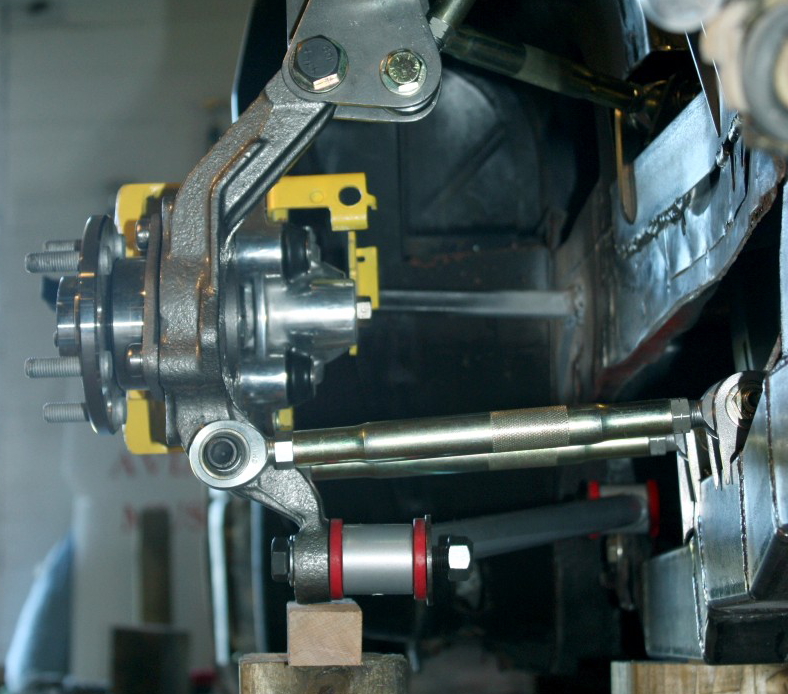
Three links down, two to go. Onwards to the upper links design!

 RSS Feed
