Within a week of having sent the 3D coordinates of the new suspension system for analysis using the Lotus Suspension Analyzer software, the results were in. And they made all of my work worthwhile. Here are the set of graphs showing how the new geometry stacks up against the stock configuration. They're the same as ones I've posted previously with the exception that I've added the pink curves which represent the dynamics of my new design. I'll explain the significance of each pink-coloured curve briefly:
Camber vs Roll:
Camber vs Roll:
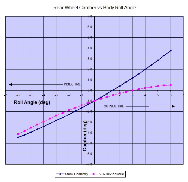
Here's one area where the new design outshines the stock Chapman strut in a big way. With the Chapman strut, the rate of camber change decreased under jounce, however the new 5-link design significantly improved the flatness of the outside tire's contact patch relative to the ground through a large range of body roll. The ratio is nearly constant at 0.75 degrees of camber gain for each degree of body roll for the outside tire. I couldn't have been happier.
Roll Center Migration vs Chassis Roll Angle:
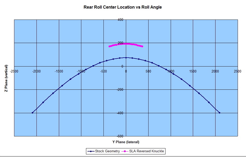
Here again the advantage of having pivoting upper lateral and upper trailing links as opposed to the semi-rigid Chapman strut allowed significant control over the roll centre movement. As before, I've drawn a scale representation of the above graph showing how the roll centre migrates on both systems during chassis roll.
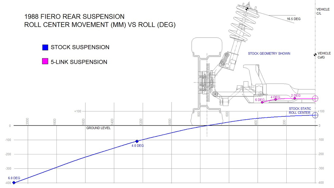
It would have been possible to eliminate roll centre movement entirely, though I needed to make a small concession in this area to keep the control arm mounts outside of the engine bay.
Roll Moment vs Bump:
Having raised the roll centre and then controlled it's movement another characteristic improved, namely, a shorter and more stable roll moment.
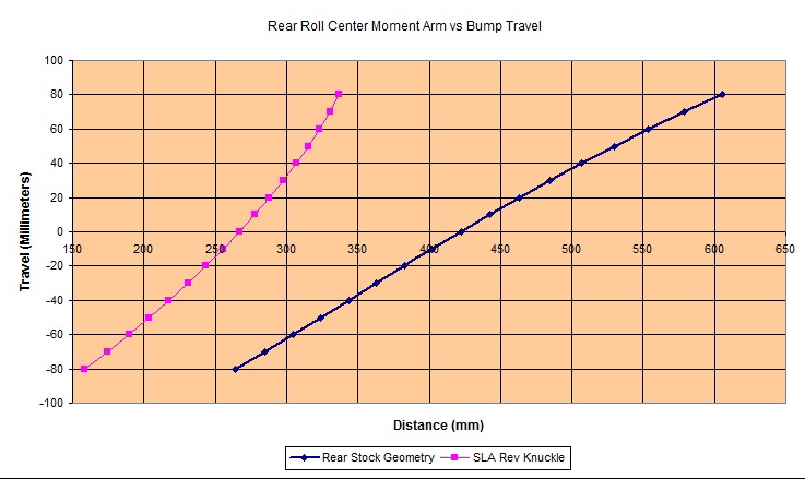
The above graph shows the distance in height between the roll center and the centre of gravity of the chassis. That distance changes as the suspension compresses and extends. The greater the difference in height between the centre of gravity and the roll center, the greater leverage that forces acting on the centre of gravity have on rolling and pitching the car. The above graph shows nearly a 40% reduction in the roll moment at most points of the new 5-link system versus stock. That's a definite advantage.
Camber vs Bump:
A negative side effect of greater camber gain in roll was also greater camber gain in bump.
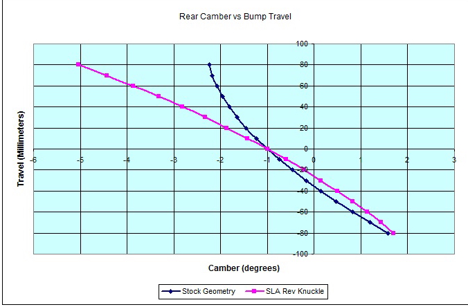
Here, the graph shows that as the suspension compresses under jounce, the camber changes more rapidly than stock. Under straight line acceleration, this results in less traction since the chassis squats, resulting in the tires being less flat with respect to the road. At least this characteristic is not one that affects safety.
Anti-Squat:
My new 5-link geometry shows that for any given amount of jounce or rebound, the anti-squat changes less than OEM through the range of travel, though there is less overall anti-squat than the stock configuration at most points.
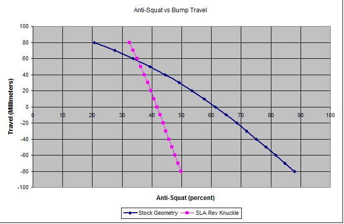
Since the angle of the trailing link is what governs the amount of anti-squat, I plan to make the forward mount of the trailing link adjustable, allowing me to dial in more anti-squat if necessary.
Toe vs Bump:
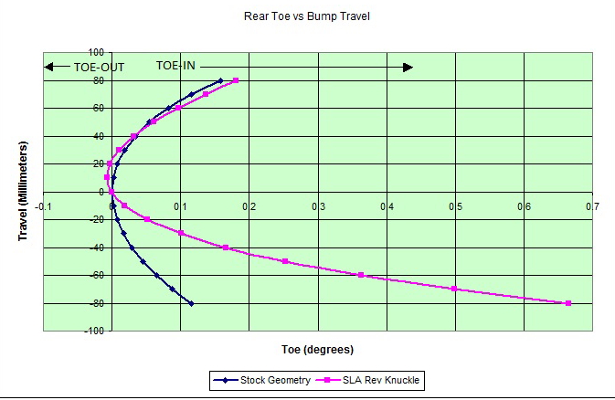
Lastly, despite having made the lower lateral links equal length (unlike the stock Chapman strut design) the graph above shows that toe basically mimics the stock Fiero suspension in jounce, where it matters most. This is certainly acceptable even though I would have preferred to have zero toe-in on the outside wheel. This will reduce the tendency for the car to oversteer at the limit.
In summary, the new 5-link suspension design met or exceeded most of my criteria despite having lowered the chassis 2 inches. The criteria that weren't met 100% are either correctable with additional adjustability in the mounts, or are insignificant from a safety stand point.
Before I could begin fabricating the upper suspension mounts, I needed to sort out the shock absorber push rod system since some of the mounts would serve double duty.

 RSS Feed
